 English




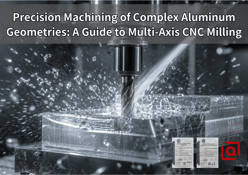
Designing precision aluminum parts on a computer monitor is clean, predictable, and forgiving. Watching a solid carbide end mill bite into a block of aircraft-grade billet at high spindle velocities while trying to satisfy unforgiving geometric callouts across multiple angled datums is an entirely different reality.
When your components step beyond basic prismatic geometry—such as deep swept pockets, multi-directional hydraulic ports, slender internal stiffener ribs, and compound-angle clearances—traditional 3-axis mills hit a practical ceiling. Operators must stop the spindle, unclamp the workpiece, flip the block, seat it into secondary soft jaws, and re-indicate datum surfaces with a dial indicator. Every single manual touch introduces stack-up variation. Reference edges drift slightly, fine chips lodge themselves under critical resting pads, and thin walls bow when clamped unevenly.
Multi-axis machining—covering 3+2 positional indexing and full simultaneous 5-axis CNC contouring—removes this operational friction. By rotating the cutting tool and workpiece in coordinated space, machines can access five open faces in a single secure setup.This guide breaks down what actually happens on our production floor when cutting complex aluminum structures: managing internal stress relief, preventing tool chatter on paper-thin ribs, and dialing in toolpaths that balance cycle times against micron-level tolerances.
1. The Real Bottleneck: Setup Drift vs.Single-Setup Freedom
When a new engineering drawing lands in our shop with features located across four or five distinct faces, the conventional approach dictates multiple setups. Machinists set up an initial fixture plate for the primary face, mill out the top pockets, manually unclamp the stock, rotate it for the bottom side, and then fabricate custom angled wedges to hit angled bores on the side faces.
This constant handling creates real manufacturing vulnerabilities:
-
Physical clamping forces fluctuate each time an operator tightens a manual vise handle, introducing minor mechanical shifting.
-
Microscopic aluminum slivers can easily hide underneath locating datums, tilting the entire part geometry by imperceptible degrees that compound across long dimensions.
-
Removing large chunks of raw metal releases natural rolling tensions locked inside the material. When a half-machined block is unbolted from its fixture, the stock breathes and relaxes, twisting holes out of mutual alignment.
Traditional 3-Axis Route (4 Setups):
[Raw Billet] -> OP10 (Top) -> Manual Flip -> OP20 (Bottom) -> Angle Plate -> OP30 (Side A) -> OP40 (Side B)
Result: Multiple opportunities for operator handling error, tolerance drift, and extended queue times.

Continuous / 3+2 Multi-Axis Route (Single Setup):
[Raw Billet on Bottom Dovetail Mount] -> Multi-Sided Cutting in 1 Cycle
Result: Every critical feature references the same master coordinate system established by an automated in-spindle touch probe.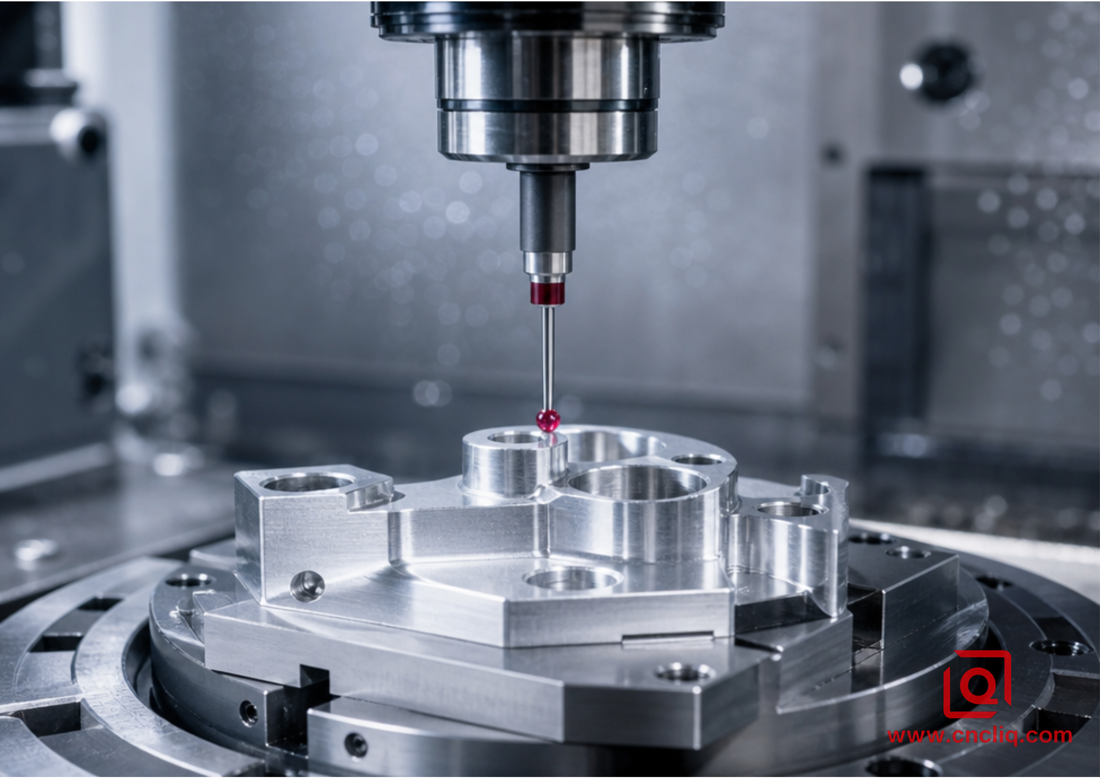
In 3+2 positional milling, the machine’s rotary axes swivel to present the workpiece directly to the cutter, locking firmly into place while the linear axes perform standard milling routines. Instead of reaching deep down into angled pockets with long, vibrating end mills that screech under load, the machine positions the workpiece so the programmer can deploy short, stubby cutters held securely in rigid holders. Cutting tool deflection drops drastically. Vibrational chatter disappears, and rough surface ridges smooth out into uniform, clean machine finishes straight from the cutting edge.
2.Aluminum Alloys Under the Spindle: Behavior, Chip Formation, and Warpage
Aluminum is universally prized for its light weight and ease of cutting, but different alloys behave distinctly once a high-speed cutter removes heavy amounts of volume. Choosing the wrong temper or alloy for a hollowed-out shape can lead to warped components long before parts reach the inspection room.
-
6061-T6 / 6061-T651: This is the everyday standard for structural hardware. It cuts cleanly, forms manageable curls of chips that clear easily under high coolant pressure, and takes anodized color finishes evenly. However, raw 6061 plate contains internal mechanical tension from the extrusion or rolling mill. We insist on using stress-relieved T651 plate stock whenever deep pocketing is involved. If a shop attempts deep asymmetrical pocketing on standard extruded stock, the component will curl upward like a shallow bowl as soon as the vise pressure releases.
-
7075-T651: An ultra-strong zinc-bearing alloy favored by aerospace and performance robotics teams. It cuts with a crisp, dry sound and produces clean, brittle chips with negligible burr formation along thin edges. It holds tight threads and sharp boundary contours exceptionally well, though programmers must program smooth deceleration arcs into tight corners to prevent microscopic chipping on fragile carbide cutting corners.
-
5052-H32: A magnesium-bearing sheet and plate alloy prized for its marine-grade corrosion resistance and ductility. On the machine bed, 5052 feels soft and gummy.Without relentless high-pressure flood coolant washing the tool flutes, chips tend to weld themselves directly onto the cutter flutes, creating built-up edges that quickly snap delicate tools.
-
Cast Tooling Plate (MIC-6): Produced as a continuous cast slab, this material is virtually free of internal mechanical stress. It will not warp or bow, regardless of how much material you hollow out from either side. It is the premier choice for multi-channel vacuum manifolds and camera alignment bases, though designers must remember that its lower tensile strength cannot support aggressive cyclical loads or deep, heavy-torque fastener threads.
Primary Aluminum Alloys in Multi-Axis Production
| Alloy & Temper State | Mechanical Strength Profile | Machining Behavior & Chip Characteristics | Cosmetic & Finishing Compatibility | Primary Engineering Applications |
| Al 6061-T651 | Moderate yield strength, high structural toughness | Predictable chip curling; requires stress-relieved T651 stock to prevent pocket distortion | Exceptional response to Type 2 clear/color anodizing and Type 3 hardcoat | General enclosures, sensor brackets, robotic linkages, structural plates |
| Al 7075-T651 | Very high yield strength, comparable to mild steel | Cuts exceptionally crisp; minimal burr creation; demands gentle corner entry toolpaths | Requires tight chemical tank control during anodizing to avoid muddy gray tones | Aerospace structural lugs, high-stress swingarms,optical chassis |
| Al 2024-T351 | High strength with superior cyclic fatigue resistance | Excellent overall chip shear; leaves clean milled walls; vulnerable to atmospheric oxidation | Lower corrosion resistance; typically calls for chemical conversion coating | Airframe components, cyclic stress brackets, hydraulic valve bodies |
| Al 5052-H32 | Lower structural strength, highly ductile | Gummy and prone to chip welding; demands polished tool flutes and flood coolant | Excellent marine corrosion resistance; clean aesthetic anodizing response | Marine sensor covers, bent sheet-and-milled hybrid assemblies |
| Cast Plate (MIC-6) | Lower tensile strength, completely stress-free | Produces fine granular chips; zero thermal or stress movement after extensive hogging | Porous grain limits cosmetic mirror polishing; functional anodizing only | Vacuum distribution plates, optical test benches, semiconductor tooling |
3. Toolpaths, Chatter Control, and Parameter Balance
Spinning a tool at high RPM through an open block of aluminum is simple. The challenge emerges when sweeping continuous five-axis toolpaths around thin vertical walls, carving deep spherical chambers without gouging, and eliminating transition witness lines where cutting passes overlap.
Tool Selection Realities for Complex Shapes
-
Flute Evacuation: We rely heavily on 3-flute carbide end mills for roughing pockets. A 3-flute tool balances tool core thickness with open flute volume, allowing large metal chips to eject upward without packing into the flutes. For finishing intricate floor surfaces and sculpted contours, specialized 2-flute and 3-flute polished cutters leave silky paths free of tool drag.
-
The Danger of Wrong Coatings: Tool coatings containing aluminum elements—such as TiAlN or AlTiN—must stay far away from your aluminum production line. Under high cutting temperatures, the aluminum content within the coating forms a chemical attraction with the workpiece material, causing fresh aluminum chips to fuse tightly to the cutting edge.Within seconds, the tool loses its sharp edge, packs with molten metal, and breaks. Instead, we use mirror-polished bare carbide or extremely thin, slippery Diamond-Like Carbon (DLC) coatings that let aluminum chips slide off effortlessly.
-
Managing Stick-Out Length: The golden rule of vibration control is keeping the cutting tool as short as humanly possible. Long tools act like tuning forks; as soon as the cutter meets the metal, it begins to hum, transferring ripples onto the side surfaces of the component.When deep features demand reach, multi-axis machines tilt the spindle head or rotate the part, sliding the entire tool holder closer to the workpiece without running long, unstable tool shanks down into the void.
Modern dynamic milling relies on high-speed machining techniques where the radial width of cut remains shallow while the axial depth of cut extends down the full length of the cutter flute. This approach spreads mechanical wear across the entire length of the carbide cutting edge rather than battering just the bottom tip. Cutting heat flows directly into the glowing, ejected chips rather than soaking into the aluminum workpiece, keeping the component cool and dimensionally stable.
4. Workholding: Keeping Parts Rigid Without Distortion
You cannot machine five accessible faces if your component is trapped halfway down inside a wide set of mechanical vise jaws.Standard vises obscure critical perimeter contours, block side-drilling tools, and push unevenly against the outer skins of fragile parts.
High-efficiency multi-axis production centers depend on three core holding concepts:
-
Dovetail Clamping:
The raw metal block visits a small preparation mill first, where a special angled cutter carves a shallow, angled dovetail track along the bottom edge of the stock. A dedicated multi-axis vise then bites onto this narrow bottom track with hardened jaws.Because the clamping mechanism grips only the disposable bottom edge, all five upper faces remain completely open to the cutting tool. The machine can profile the entire outer envelope, drill angled through-holes, and hollow out interior pockets without a single clamp obstruction. Once finished, a quick second operation slices off the tiny dovetail tab.
-
Zero-Point Receiver Baseplates:
Pneumatic or hydraulic pull studs are mounted directly to the underside of the workpiece or holding sub-plates. These studs snap into precision receiver chucks permanently installed on the machine table. Operators can swap entire setups in seconds without picking up an edge finder or measuring offset values, maintaining absolute positioning precision across shifts.
-
Vacuum Chucking and Profiled Soft Jaws:
When carving large, thin-walled electronic housings, standard mechanical clamps pinch the perimeter, causing the center of the part to bulge upward. When the clamps are released after cutting, the center springs back down, leaving the floor sunken and uneven. Using custom vacuum plates fitted with closed-cell rubber gaskets, atmospheric air pressure presses the wide, flat floor down evenly across its entire footprint, preventing localized distortion.
5.Shop Floor Case Study: Multi-Angle Aerospace Sensor Housing
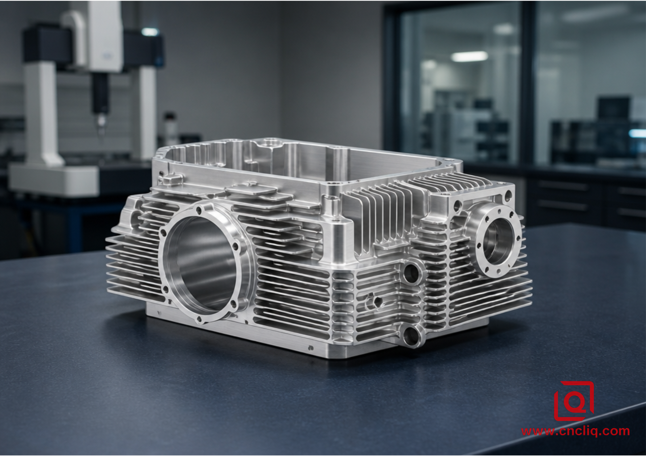
The Component Challenge
A Tier-1 aerospace integration partner approached our engineering desk with an optical tracking sensor housing intended for an autonomous surveillance platform.
-
Material: 7075-T651 solid billet.
-
Overall Envelope: Roughly the size of a thick hardback book, packed with internal electronic mounting cavities.
-
Critical Design Hurdles:
-
Four angled internal optical bore chambers positioned at awkward compound angles relative to the main mounting face.
-
Internal sensor mounting bores requiring precise slip-fit clearances.
-
Strict true position callouts relative to the primary mounting face and locating dowel holes.
-
An array of tall, slender thermal dissipation fins running along the exterior wall, requiring uniform wall thickness without surface chatter.
-
 [Top Sensor Bore: Strict True Position Callout]
                       |
     +----------------+----------------+
    / \
   / [Compound Angle Port] \
  |                                         |
  |     [Deep Slender Heat-Sink Ribs] |
  |                                         |
   \ [Compound Angle Port] /
    \ /
     +----------------+----------------+
                       |
         [Bottom Dovetail Clamping Tab]
The Initial Manufacturing Snag
The client's internal machine shop had initially attempted to build prototypes on a standard 3-axis vertical mill using stacked sine plates and multiple angled indexing blocks.
The manufacturing process quickly unraveled. Because the operator had to unseat and re-align the stock four separate times to bring the angled sensor holes normal to the vertical spindle, mechanical locating errors compounded. Inspection on their coordinate measuring machine revealed that the intersecting optical paths missed their target centerline targets. Nearly half the pilot parts were scrapped. Furthermore, attempting to clear out the deep exterior cooling fins using a long, slender end mill caused violent harmonic vibration, leaving rough ripple marks along the delicate walls that failed cosmetic and functional specifications.
The Multi-Axis Engineering Solution
We transitioned the manufacturing plan to a high-precision 5-axis trunnion machining center with a high-speed thermal-shrink tool holding system.
-
Stock Preparation & Stress Relief:
We cut an oversized 7075-T651 aluminum block and milled a clean dovetail tab on the base. Using dynamic milling paths, we roughed out the heavy interior cavities, removing roughly 80 percent of the waste metal while leaving a small, uniform skin of stock across all faces.We then released the vise clamping pressure entirely, letting the part rest in our climate-controlled cell to allow internal mechanical rolling strains to equalize naturally.
-
Automated Re-Probing:
After the brief resting stage, the machine's spindle probe touched off multiple key references to re-verify the coordinate system, absorbing any minor shape movement that occurred during roughing.
-
Compound Angle Boring:
Instead of stacking custom angle fixtures, the trunnion table rotated the part smoothly, presenting each angled port directly to a rigid, balanced boring assembly held in a heat-shrink tool holder.Each bore was brought to final diameter in a single, stable plunging sequence without tool chatter or dimensional taper.
-
Synchronized Flank Milling on Slender Fins:
To resolve the severe vibration on the tall exterior fins, our CAM programmers abandoned traditional multi-pass stair-step cutting. We programmed a synchronized five-axis continuous swarf cut, tilting the cutting tool so the entire side edge of a solid carbide barrel tool rested flush against the fin wall. The cutting forces balanced along the flank of the tool rather than concentrating at the tip, stabilizing the slender aluminum rib and wiping away harmonic chatter.
Production Results and Dimensional Verification
| Inspection Parameter | Engineering Requirement | Initial 3-Axis Multi-Setup Outcome | Multi-Axis Production Outcome | Metrology & Verification Method |
| Bore Diameters | Tight slip-fit clearance (+0.008 mm maximum limit) | Bore tapered and out-of-round; failed pin-gauge check | Cylindrical, round, and on-target | Pneumatic air gauge and precision bore micrometer |
| True Position | Tight tolerance relative to Datums A, B, and C | Exceeded tolerance envelope due to accumulated setup drift | Well within required geometric tolerance boundary | High-precision bridge-type CMM |
| Thin Wall Finish | Smooth texture suitable for hardcoat anodizing | Heavy harmonic chatter ripples and distinct steps | Clean, consistent, satin-smooth milled surface | Contact stylus profilometer measurement |
| Setup & Cycle Time | Commercial production baseline | Extended run time across four separate fixtures | Single-cycle completion with in-process deburring | ERP digital machine monitoring logs |
| Production Yield | High-reliability batch target | Scrap rate over 40 percent | Stable run approaching 100 percent acceptance | Final QA sign-off and receiving logs |
6. Industry Quality Standards: Proving Precision on Paper
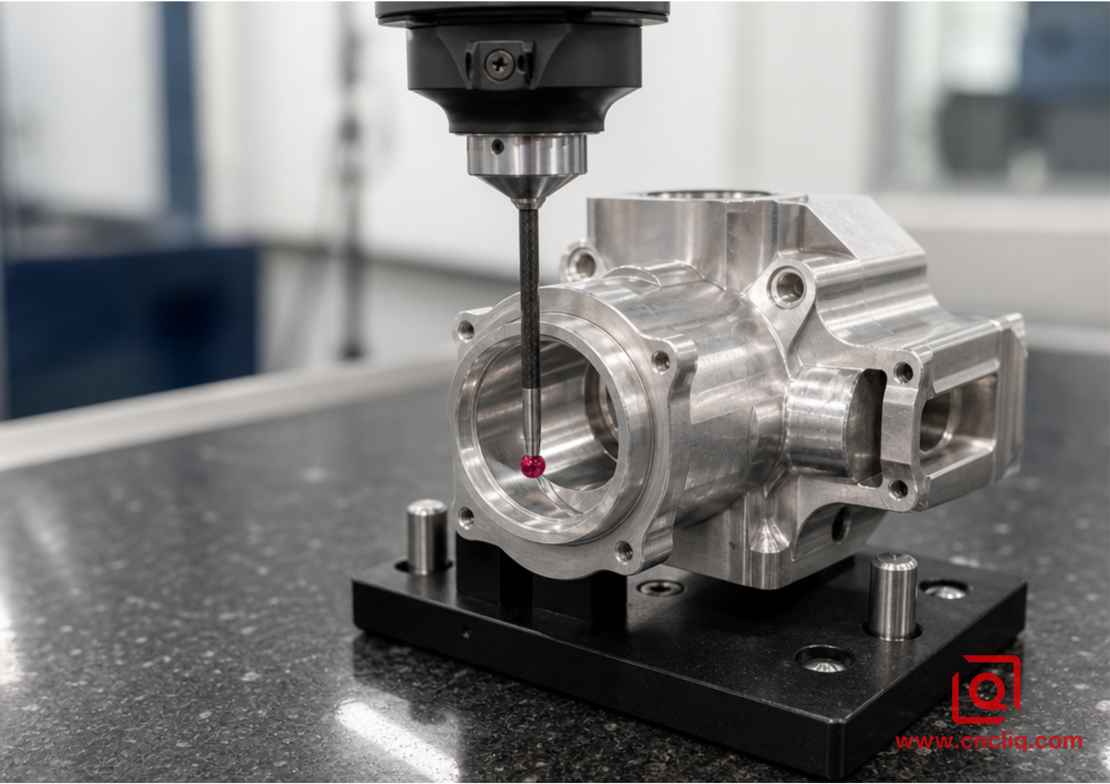
Claiming precision on a digital marketing page means nothing to a quality manager unless every dimension is verified against standardized international metrology guidelines.When buying custom OEM aluminum parts, confirm that your manufacturing partner measures their work against these industry baselines:
-
ISO 2768-m / ISO 2768-f: These standards define linear and angular dimensional tolerances for features without dedicated tolerance callouts. High-grade multi-axis aluminum setups routinely hold the fine (f) standard across complex geometric transitions.
-
ASME Y14.5 / ISO 1101: The modern authorities on Geometric Dimensioning and Tolerancing (GD&T). When verifying 5-axis contoured surfaces, true position, perpendicularity, runout, and profile of a surface must be evaluated from functional physical datums rather than simple point-to-point calipers.
-
ISO 9001 / AS9100 Quality Frameworks: Ensures that every single aluminum bar entering the building carries a legitimate Mill Test Report confirming chemical composition and mechanical temper, that in-process coordinate measuring equipment remains traceable, and that first-article inspection records follow the component throughout its operational life.
7.Actionable DFM Advice for Mechanical Design Engineers
Before locking your 3D CAD files and releasing drawings for manufacturing quotes, review this practical checklist to save machining time and avoid production hold-ups:
-
Open Up Your Internal Pocket Radii: Never design internal vertical corners with sharp 90-degree transitions. When an end mill cuts into an internal square corner, its contact angle doubles instantly, causing the tool to grab, shudder, and leave gouges. Make your corner radius noticeably larger than standard cutter dimensions. If your cavity depth suggests using a 6 mm tool, make the internal corner radius 3.5 mm or larger.This allows the CAM toolpath to sweep around the corner smoothly without slowing to a dead stop.
-
Watch Your Cavity Depth-to-Width Ratios: Try to keep internal pocket depths within four to six times the tool diameter. Extremely deep, narrow slots force machinists to run slender, extended-reach cutters at painfully slow feeds, inflating spindle runtime and driving up piece-part prices.
-
Provide Reliable Probing Surfaces: Even fully automated 5-axis machines need a physical place to start. Always leave at least one pair of mutually perpendicular, flat, accessible reference surfaces somewhere on your exterior geometry.This allows our automated touch probes to find true component coordinates cleanly.
-
Be Selective with Tight Tolerances: Avoid applying blanket title-block tolerances across every feature of a complex model. Reserve tight micrometer-level bands for bearing press-fits, locating dowel holes, and critical O-ring sealing faces. Open up exterior clearance covers, cosmetic pockets, and weight-reduction reliefs to general manufacturing standards. Relaxing non-critical surfaces cuts machining runtimes significantly and protects your program budget.
FAQs
Q1: When is full continuous 5-axis milling strictly necessary, and when is 3+2 positional machining sufficient?
A: In over 70 percent of OEM aluminum projects, 3+2 positional machiningis actually the more efficient and cost-effective choice.3+2 milling rotates and locks the workpiece at specific compound angles, allowing standard, short-reach rigid tooling to mill flat faces, pocket profiles, and angled holes without continuous multi-axis interpolation. Full continuous 5-axis milling (where all 5 axes move synchronously) is reserved for dynamically changing freeform surfaces—such as turbine impellers, complex aero-surfaces, organic industrial enclosures, or deep barrel-cutter swarf passes along curved, draft-angle ribs. Choosing 3+2 whenever geometry allows delivers superior surface rigidity, eliminates axis reversal micro-marks, and keeps machine-hour rates lower.
Q2: Why does large-scale pocketing in aluminum sometimes result in warped parts even when cut on a 5-axis machine?
A: Multi-axis capability guarantees spatial precision during cutting, but it cannot override the laws of metallurgy. Solid extruded or rolled aluminum blocks retain internal manufacturing stresses from their initial rolling, quenching, and drawing phases. When heavy roughing cuts remove 60 to 80 percent of the raw billet's mass unevenly, those internal stress planes shift and equalize, causing the part to twist or bow once removed from the machine.To prevent this, two production rules must be followed: first, specify stress-relieved T651 plate stock (which underwent controlled stretching after heat treatment); second, introduce an intermediate stress-relaxation step where clamping torque is released after heavy roughing, allowing the material to breathe naturally before taking final finishing passes.
Q3: How do we prevent cutter chatter and rough stepped marks on tall, thin-walled aluminum ribs?
A: Machining deep, slender walls using long, conventional end mills produces harmonic resonance—the tool deflects slightly, bites, releases, and creates visible washboard chatter ripples along the surface. In multi-axis milling, this is eliminated through 5-axis swarf (flank) milling.Tilting the spindle lets the entire flute profile of a barrel or tapered cutter ride tangent against the pocket wall. That moves tool pressure along the whole flank instead of chewing up the tip. Run that path with tight radial stepovers under heavy flood coolant to calm thin-walled aluminum down, kill chatter, and pull off a clean, satin-smooth pass.
Q4: Why shouldn't standard TiAlN or AlTiN tool coatings be used when milling precision aluminum?
A: TiAlN and AlTiN target hard alloys and steels, not aluminum. Push these tools hard in a high-speed cut, and the aluminum inside the coating literally grabs the workpiece material.Hot chip debris welds directly to the flute surfaces—classic built-up edge (BUE). Once that happens, relief angles disappear, chip flow chokes, and the end mill snaps. For tight-tolerance aluminum parts, run bright, uncoated solid carbide or lay down a slick, micron-thin DLC (Diamond-Like Carbon) film so chips slide away cleanly.
Q5: Can multi-axis CNC milling replace wire EDM for intricate internal corners and slots?
A: Multi-axis milling easily swaps in for wire EDM on angled undercuts, compound ports, and drafted ribs, cutting cycle times down by days. Still, spinning cutters physically cannot yield dead-sharp 90-degree internal square corners. Unless designers open those inner fillets just past standard tool radii, wire or sinker EDM remains your only move for zero-radius slot intersections.
Request an Engineering Review & Production Quote
Multi-axis machining translates bold mechanical concepts into robust, tangible metal hardware. Whether you are developing dynamic multi-link robotic arms, high-pressure fluid manifolds, or ruggedized field optoelectronic packages, pairing the proper aluminum temper with advanced multi-axis toolpaths guarantees dependable strength, consistent fit, and clean surface quality.
Submit your 3D CAD models (.STEP, .IGES, or native formats) along with your 2D engineering drawings to our technical team today for a comprehensive DFM evaluation, cycle time estimate, and competitive manufacturing quotation.
Contact Information
Disclaimer
All technical articles, material specifications, machining recommendations, and surface treatment details published on this blog are for informational and reference purposes only. Please note that general blog insights do not replace signed technical agreements. Because custom parts vary by material heat numbers, machine calibrations, and specific tolerances, binding quality specs are governed solely by your approved CAD drawings, signed contracts, and formal quality plans.
All customer case studies featured on this blog have been thoroughly anonymized and sanitized.The performance metrics, manufacturing workflows, and imagery displayed serve solely to demonstrate our custom machining capabilities and do not represent a single universal standard for all orders.
Liqin Manufacturing Team
Built on 18 years of precision engineering experience, Ningbo Liqin Industry manufactures high-tolerance metal components for demanding global markets. We operate out of a 6,500 m² production hub equipped with over 150 machines, running 4-axis and 5-axis CNC machining, mill-turn machining, cold extrusion, and pressure die casting under one roof. This setup allows us to manage projects seamlessly, taking parts from initial CAD concepts directly to finalized shipments.
We handle quality control with zero compromise. We treat tight tolerances with the engineering discipline they require. Backed by ISO 9001, ISO 13485, and IATF 16949 certifications, our QA engineers run strict IPQC, FQC, and OQC checks on every single production batch. From CMM dimensional mapping and optical profiling to hardness and salt-spray testing, we validate your critical specs upfront—so you receive drop-in ready components with zero assembly headaches or costly line stoppages.On top of manufacturing, you can rely on us for two-hour response times on new RFQs, direct support for prototype sampling, and smooth export shipping across Europe, North America, Asia, and Oceania.
Welcome your inquiries and samples.Visit our website or contact us directly for a competitive quote!
