 English




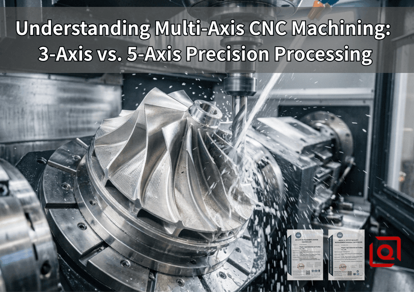
Let's cut the fluff. If your mechanical engineer is still designing complex aerospace manifolds or medical-grade titanium bone plates under the assumption that a standard 3-axis vertical machining center (VMC) can "just figure it out with a few extra setups," you are bleeding margin. You are also accumulating volumetric errors that no coordinate measuring machine (CMM) will let slide.
I’ve spent the last decade staring at toolpaths, and if there is one hard truth in high-precision CNC machining, it is this: setup multiplication is the silent killer of concentricity.
The Reality of "3+2" vs. Continuous 5-Axis: Not All Rotations Are Created Equal
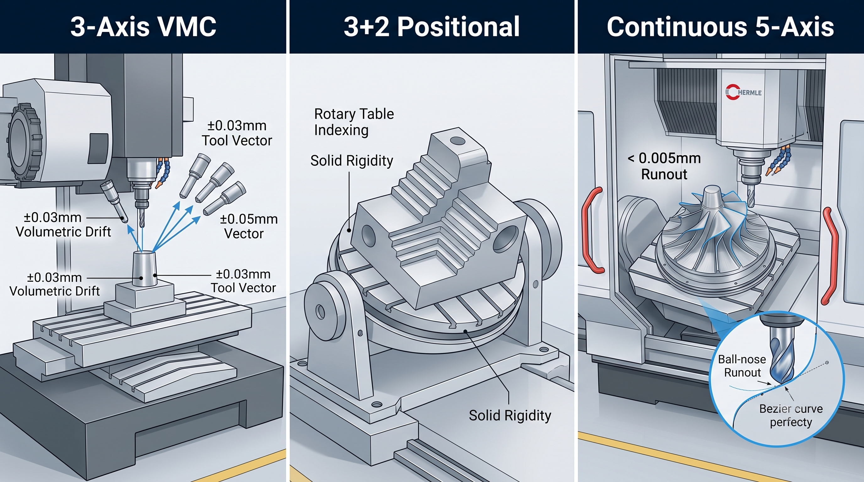
When people talk about multi-axis, they often blur the line between positional 5-axis (3+2) and true, simultaneous continuous 5-axis. Let's make a critical operational distinction here.
[3-Axis VMC] ──(Setup Cumulative Errors)──> ±0.03mm Volumetric Drift
[3+2 Positional] ──(Rotary Table Indexing)──> Solid Rigidity, Stepped Surfaces
[Continuous 5-Axis] ──(XYZ + AB Simultaneous)──> True Sculpted Surfaces, Under < 0.005mm Runout
If you index a dual-axis tilt-rotary table (say, an A-axis tilting -120° to +30° and a C-axis rotating a full 360°) to machine a deep pocket, lock it down, and run a standard 3-axis program, you are running positional 3+2. It's rigid. It's great for hogging out bulk aircraft-grade Aluminum 7075-T6 with a coarse indexable face mill. But the second you need to blend a 3mm ball-nose end mill across a complex Bezier curve on an impeller blade, positional indexing will leave a witness line. That transition step, sometimes as small as 0.015mm due to structural deflection or rotary backlash, requires manual benching (hand-polishing).
Shop Floor Reality: Hand-polishing immediately destroys your profile tolerance of ±0.02mm specified under ISO 1101 standards. If an operator takes a Scotch-Brite wheel to a critical aerodynamic surface to "smooth out the witness lines," you can kiss your geometric dimensioning and tolerancing (GD&T) runout spec goodbye.
A Case Study in Pain: The Thin-Walled Ti-6Al-4V Impeller
Let's talk about actual metal. We recently ran a batch of medical-grade Titanium (Ti-6Al-4V) impellers. The initial RFQ came in with a design suggesting a standard 3-axis indexing setup. The web thickness of the blades was 0.8mm, tapering down to 0.4mm at the trailing edge.
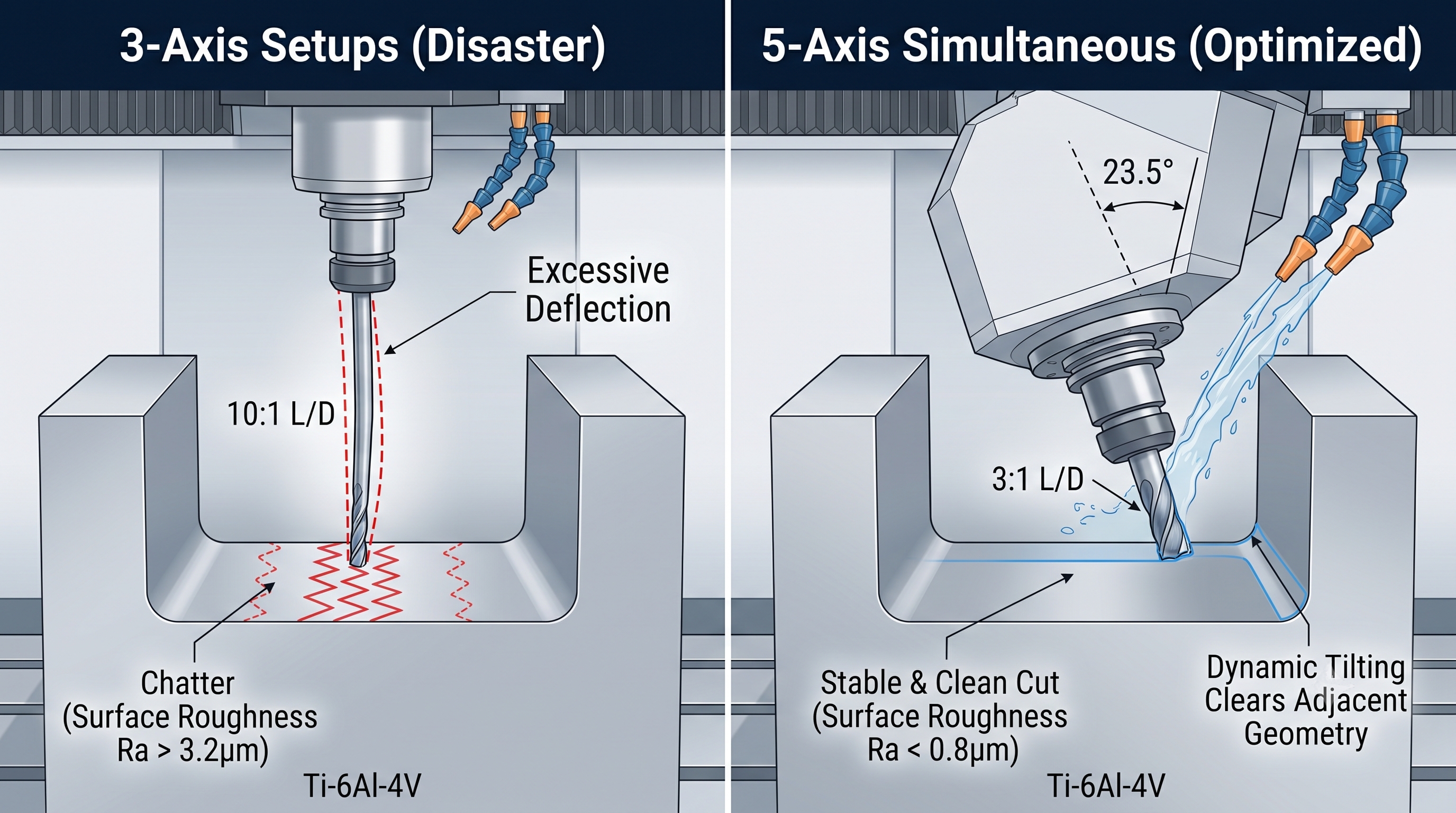
Here is exactly why a 3-axis setup was a disaster in the making, and how we re-engineered the process for simultaneous 5-axis on our Hermle C42 machining center:
    3-Axis Setups (Disaster)               5-Axis Simultaneous (Optimized)
      [Tool: Long Reach]                         [Tool: Short & Rigid]
             |                                             |
             v (Deflection & Chatter)                      v (Stable & Clean)
      [======|======] <--- Blade (0.4mm)            [======|======]
             |                                            /
            / \                                          / \
      Yields: Surface Roughness Ra > 3.2µm         Yields: Surface Roughness Ra < 0.8µm
On a 3-axis machine, to reach the undercut areas between the overlapping blades, you have to use an extended-reach tool. A 4mm solid carbide end mill with a 40mm neck length has a length-to-diameter (L/D) ratio of 10:1.
Do the math on tool deflection:
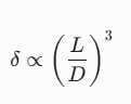
By increasing the overhang, your tool deflection (δ) increases exponentially. At a feed rate of 1200mm/min and spindle speed of 8000RPM, that 10:1 tool will chatter like crazy. It yields a surface roughness (Ra) worse than 3.2μm and leaves micro-cracks in the titanium.
The 5-Axis Solution:
We loaded the job onto the C42, utilizing a short, stubby 4mm taper neck end mill (L/D ratio of only 3:1). By continuously tilting the A-axis at a dynamic angle of 23.5° to clear the adjacent blade geometry, we kept the tool's cutting point exactly on its center axis while maintaining a constant chip load.
We ran this with:
-
Spindle Speed: 14,000RPM
-
Feed per Tooth ($f_z$): 0.04mm/tooth
-
Coolant: High-pressure through-spindle water-soluble oil at 70bar(7.0 MPa)to blast away re-cutting chips.
The result? A pristine surface finish of $R_a\ 0.6μm straight off the machine—zero manual benching needed, and the CMM report showed a profile tolerance deviation of less than 0.004mm.
Step-by-Step: Calibrating the Kinetic Chain for 5-Axis Simultaneous Cuts
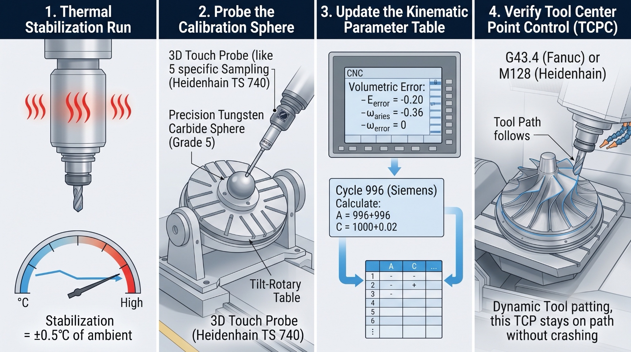
Do not let your supplier tell you they run simultaneous 5-axis if they do not regularly calibrate their machine’s kinematic center of rotation. A machine's physical pivot points shift with shop temperature variations. A 3℃ swing in the hangar can cause the spindle headstock to thermal-drift by up to 15μm.
If you are auditing a factory, look for these specific operational steps:
Critical Parameter Comparison: 3-Axis vs. 5-Axis Processing
If you are drafting a request for quote (RFQ) or trying to optimize an existing design, keep these hard technical parameters in mind.
| Engineering Parameter | 3-Axis Vertical Machining Center | Continuous Simultaneous 5-Axis |
| Volumetric Profile Tolerance | ≥ ±0.025μm (due to multiple setups) | < ±0.005mm (single setup, active TCPC) |
| Surface Finish Capability ($R_a$) | 1.6μm - 3.2μm (due to long overhang tools) | 0.4μm - 0.8μm (stubby, rigid tools) |
| Achievable Wall Thickness Min. | ~1.2mm (vibration causes deflection and wall failure) | Down to 0.3mm (constant optimal tool-to-part engagement) |
| Typical $L/D$ Ratio of Cutter | 8:1 to 12:1 (needed to clear complex walls) | 3:1 to 5:1 (optimized tilt clears walls easily) |
| GD&T True Position capability | Within ∅0.15mm across three setups | Within ∅0.02mm in a single setup |
The Hard Truth on Tool Wear:
When milling a sloping cavity on a 3-axis machine, the tool’s tip speed at the very center is technically 0 m/min. This means you aren’t cutting; you are rubbing and burnishing the metal, which wears out the tool tip in less than 30 minutes on material like Inconel 718. With simultaneous 5-axis, by tilting the tool 15° to 20° off-vertical, you utilize the full effective cutting diameter of the ball-nose flutes, increasing tool life by up to 300% and avoiding work hardening of the workpiece surface.
FAQs
Q1: Why can't we just use a 3-axis VMC with indexable rotary fixtures (like a manual 4th/5th axis) to save machine hour rates?
A: Because manual indexing breaks your datum consistency. The moment an operator manually releases a fixture to index it to a new orientation, you introduce clamping errors and geometric variations ranging from 0.03mm to 0.08mm. Furthermore, without active TCPC (Tool Center Point Control), your operator must recalculate and touch-off the work coordinate system (WCS) offset for every single angle change. That is a recipe for manual calibration errors and massive cycle-time bloat. If your drawing specifies a GD&T true position of under ∅0.05mm, manual indexing is out of the question.
Q2: What is the real-world threshold where 5-axis simultaneous cutting is actually cheaper than multiple 3-axis setups?
A: The mathematical break-even point usually occurs when a part requires more than 3 separate setups to machine all features, or when the geometry demands a tool aspect ratio (L/D) greater than 6:1. While a 5-axis machine has a higher hourly rate (often 1.5x to 2x that of a 3-axis VMC), it reduces labor-intensive fixture design, eliminates setup times, and slashes scrap rates. If you factor in the benching (hand-polishing) labor required to clean up 3-axis tool marks, 5-axis simultaneous cutting is often 15% to 30% more cost-effective for complex components in batches as small as 10 pieces.
Q3: Does 5-axis machining cause faster tool wear due to the complex multi-axis motion?
A: Absolutely the opposite, provided your CAM programmer knows what they are doing. On a 3-axis machine, when cutting a sloped cavity or surface, the center tip of a ball-nose end mill has zero relative cutting velocity, leading to material dragging, rapid chipping of the tool tip, and severe surface work-hardening. In continuous 5-axis machining, we utilize lead/tilt angles (typically 15° to 20°) to shift the active cutting zone away from the dead center of the ball-nose tip to the flutes. This keeps the effective cutting speed (Vc) constant, reducing thermal load on the tool and extending cutter life by up to 300%.
Q4: How do you prevent internal mechanical backlash from ruining tolerances on older or heavily used 5-axis centers?
A: Backlash in the rotary axes (A and C) is the primary cause of ovality in 5-axis bored holes. In our workshop, we don't rely solely on software compensation parameters. For critical finish cuts, we utilize one-way rotational indexing (approaching the coordinate angle from the same direction to keep the gears loaded against one another) and dynamic hydraulic locking of the rotary brakes when the axis is momentarily positional. Additionally, we run laser interferometer checks every 3 months to map and compensate for pitch error and volumetric deformation down to the sub-micron level.
Q5: Is there a physical wall-thickness limit where even simultaneous 5-axis machining cannot prevent structural vibration?
A: Yes. Once your wall thickness drops below 0.3mm on aerospace aluminum or 0.2mm on titanium, the workpiece itself behaves like a tuning fork. No matter how rigid your 5-axis setup is, the radial cutting forces will cause thin-wall deflection and micro-chatter. To push past this physical limit, we use custom sacrificial paraffin wax or low-melting-point alloy backing to fill the cavity and damp the vibration during outer-profile finish passes. The backing is later melted out in a 70℃ oil bath, leaving the pristine thin walls completely untouched.
Summary
Ultimately, forcing a 3-axis VMC to handle complex, multi-sided geometries introduces setup drift (≥ ±0.025mm), tool deflection, and manual polishing lines that scrap your GD&T specs. Transitioning to continuous 5-axis machining is a critical process choice that keeps cutting velocity (Vc) constant to prevent work hardening, slashes tool aspect ratios, and holds true profile tolerances under < ±0.005mm in a single setup. For complex, thin-walled parts requiring Ra0.6μm finishes straight off the mill, simultaneous 5-axis is the only way to guarantee your margins and design integrity.
If your manufacturing partner is still quoting complex structural blocks with multiple setup fixture fees, it is time to ask them hard questions about their kinematic calibration cycles and their simultaneous 5-axis capabilities.
Contact Information
Disclaimer
The parameters and engineering data presented in this article are based on specific workshop testing environments. Actual machining setups and results may vary depending on material grades, tooling brand, and machine rigidity. Always consult with our engineering team for a dedicated DFM review before finalizing your design.
