 English




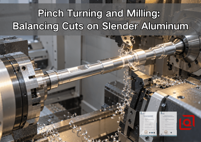
Still chasing a slim aluminum shaft that is right beside the chuck and wrong in the middle? Been there. The finish looks decent, spindle load is calm, then the micrometer finds a fat patch exactly where the part had the most room to bend. This article is about that problem - and about when two opposed tools are actually worth the trouble.
A quick warning before the clever part: pinch turning does one job well. It can reduce sideways load on a flexible span. It does not cancel heat, torque, axial force, crooked stock, a tired center, or a loose turret. Keep that distinction and the rest of the process makes sense.
A Shop-Floor Note Before the Theory
A trial from the notebook. Upper tool was doing the work; lower tool was mostly along for the ride. You could see it in the chips before the load bars made it obvious. Top chip: tight curls. Bottom: a thin silver ribbon, then a bird's nest. We stopped there.
Centerline got checked again with the test bar. Lower station was low, not much, but enough. Its holder also stuck out 6 mm farther because somebody wanted space for the coolant line. We moved the line, shortened the holder, fitted two edges from the same lot, and started over.
Second pass sounded boring. Good. The shaft measured boring too: no fat patch halfway along. That is what I want from pinch turning. Not a spectacular cycle, just both tools doing roughly equal work while the flimsy bit stays where the program thinks it is.
There are catches. Heat stays. So does torque. A dirty center does not become clean because there are two turrets. Chips are worse, if anything; now there are two streams looking for a finished surface to scratch. We aimed one forward and one down, then watched three complete cycles before calling it settled.
Would not use the setup for five pieces. Too much proving. For a repeat order, different answer. I also would not write "use pinch turning" on a drawing. Put the function on the drawing - runout, straightness, diameter, finish, datum - and let the shop choose the route.
Material note from that job: 6061-T6 extruded bar, certificate required. Not just "aluminum." Stock form matters. So does the allowed center hole. Those two lines on the RFQ saved more time than another page of general tolerances.
Final pass? One tool owned the seal journal on this part. We used both for roughing, kept the center in, then let the upper edge own size. Next job could be different. Measure the free part, write down the support points, and decide from evidence.
1. What Pinch Turning Means at the Machine
Picture a normal OD cut. The insert shears metal from the rotating bar, but it also pushes the bar sideways. Close to the chuck, no drama. Farther out, a reduced section gives a little. The tool then removes less material there and the finished diameter grows.
Now bring a second tool in from the other side. Put both tips at about the same Z station. If they take comparable cuts, one pushes north while the other pushes south. The shaft is no longer asked to resist the full radial load from one direction.
Simple sketch. Fussy reality.
A few terms get mixed together, so here is the shop version:
1. Symmetric pinch turning means opposed tools cutting the same local band.
2. Follow turning means one tool trails the other. Rough first, finish behind it. Useful for cycle time, but not the same local force balance.
3. Pinch milling means two driven cutters working opposite faces of a long rib or blade-like piece.
4. Twin-spindle work means a main and sub-spindle share the part. That alone is not pinch cutting.
The control and post matter as much as the iron. Autodesk's multi-turret setup guide calls for opposing turrets and a compatible postprocessor. Its PartMaker pinch-turning procedure deals with separate tools, finish allowance, a primary toolpost, and the correct sync mode. Good questions for a supplier, by the way. "How are the channels synchronized?" tells you more than "Is it a twin turret?"
Flat or cross hole on the print? Back up a step. That fork in the road is covered in Liqin's guide to choosing 3-axis, 5-axis, or mill-turn machining: fight the bending, or just keep the features on one datum?
2. The Material Cuts Fine. The Shaft Still Springs
A note from an early trial: clean chip, light spindle load, lousy mid-span size. Nothing contradictory about that.
Aluminum usually needs less cutting power than steel. It is also much less stiff. Common 6061-T6 sits near 69 GPa elastic modulus. The NIST-hosted machining paper discusses aluminum's relatively low turning force and the value of sharp, positive-rake tools for ductile grades.
Geometry is the bully here. In the simple cantilever model, deflection scales with force times unsupported length cubed, divided by 3EI. For a round section, I depends on diameter to the fourth power.
What does that mean without the symbols?
1. Double the free length and the idealized movement becomes eight times larger.
2. Halve the diameter and it becomes sixteen times larger.
3. Move support closer to the cut and the whole situation can change.
Those are warnings, not promised machine results. A real part may have a live center, steady rest, guide bushing, shoulder, or sub-spindle changing the boundary conditions. Still, the math explains why turning down the feed often disappoints. The long, thin geometry is still long and thin.
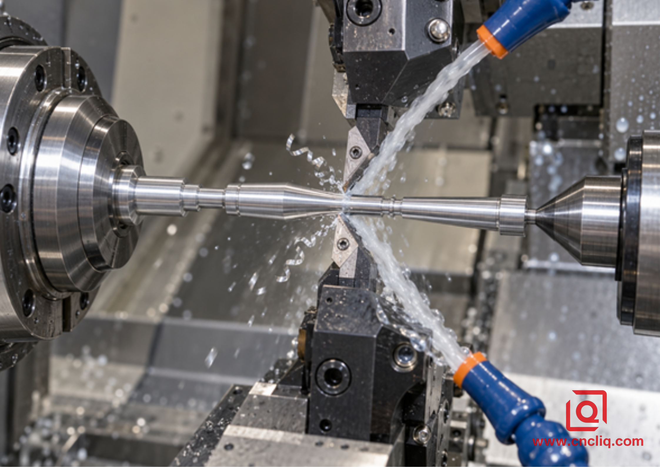
Two tools help when their radial loads are genuinely similar. "Same insert" is not enough. We once found one holder sticking out farther because the coolant line needed room. Same box of inserts, same programmed depth, different stiffness. The lower turret barely shared the work.
Check the small things:
1. Center height.
2. Nose radius and edge preparation.
3. Holder stickout.
4. Actual depth on each side.
5. Edge wear.
6. Chip shape and load split.
If one edge collects built-up aluminum, the balance changes during the batch. The code did not move. The force did.
3. When Two Tools Earn Their Keep
Would I pinch turn five prototypes? Probably not. Setup and proving can cost more than the saved cutting time. A live center and one patient tool may be the honest route.
A repeating family of actuator rods is different. So is a long journal controlled for total runout at mid-span. That is where the extra planning can pay back.
|
Route |
Good fit |
Main advantage |
Watch closely |
|
Single tool |
Short, firm projection |
Simple and quick to prove |
Middle-section push-off |
|
Tailstock, rest, or guide bushing |
Long shaft with a usable support surface |
Stiffness near the edge |
Pressure, marks, alignment |
|
Symmetric pinch turning |
Repeated slender shafts on opposed turrets |
Less net radial load |
Mismatched tools and tangled chips |
|
Follow turning |
Coordinated rough and finish work |
Shorter cycle |
Rear tool follows a warm moving surface |
|
Pinch milling |
Long thin ribs between rotary axes |
Opposed loads on a weak section |
Phase, collision, changing wall stiffness |
Do not pick a process from L/D alone. Mark the controlled feature. Is it a seal diameter? Straightness across the whole shaft? Total runout to datum A? Position of a cross hole? A short neck with support nearby is not the same animal as a long open span of the same diameter.
One more practical limit: access. Two holders need room. So do two coolant streams and two chip paths. A flange may block the lower turret. A fork may force the second tool away from the critical band. In that case, pinch rough the open diameters, retain a temporary support pad, and finish the obstructed area another way.
4. Prove It Before Turning Up the Cut
The first dry run should look almost boring. Both toolholders clear the chuck. Both clear the tailstock or sub-spindle. No nozzle swings into a jaw. The simulation uses the actual machine, not a hopeful generic model.
Our setup-sheet questions are plain:
1. Are both tool tips on center mechanically?
2. Were the two nose radii and lengths measured separately?
3. Can the holders pass every shoulder without stealing clearance from each other?
4. Is there a single-tool baseline on this alloy, temper, bar lot, coolant, and support setup?
5. Where do the top and bottom chips go?
6. How will the free part be measured after release?
Start with one tool. Record sound, chip, load, taper, and surface. Add the second with modest engagement. Top bar up, bottom bar asleep? Pause there. Do not correct that with an offset until the cause is known.
Also, no automatic "two tools, twice the feed." Each edge still needs a valid chip thickness and surface speed. The spindle sees combined torque. The chuck transmits it. Each turret has a thrust limit. Chip evacuation has just become twice as crowded.
Once the cycle behaves, write down more than X offsets. Note warm-up, coolant condition, insert change rule, acceptable load difference, nozzle aim, support pressure, first-piece checks, and what the operator does when the chip changes. Otherwise the good first article is just a good day.
5. Aluminum Details That Upset the Pair
A drawing that says only aluminum leaves a hole in the job. Use alloy, temper, and stock form. Stock form has paperwork too: ASTM B221 is used for extruded bar, rod, wire, profiles, and tube; B211 is used for rolled or cold-finished bar, rod, and wire. Put the two bars on the rack and they may bring different straightness and stress histories to the job.
No casual temper swaps, either. Those T6, T651, and T351 endings are not decoration. Keep the approved alloy and temper. Design approval comes first.
For a general wrought-aluminum trial, I would begin with a sharp precision-ground, positive-rake insert made for ISO N material. Usually polished. After that, open the maker's chart for that edge - not the nearest-looking one. Keen carbide, a low-friction grade, or PCD? Liqin's aluminum insert geometry guide walks through that choice.
First thing I watch for is aluminum stuck to one edge. A silver skin welds to the top insert. Its effective geometry changes. Force rises there, the shaft bends away, and now a once-balanced cycle makes taper. The article on built-up edge in soft aluminum explains why timid feeding can rub rather than cut.
Our first checks are not exotic: fresh matched edges, enough feed to form a chip, approved lubricant reaching the contact, and separate chip exits. Watch three full cycles. A ribbon that looks harmless on part one may be wrapped around a finished journal on part four.
Final size deserves its own plan. On a seal journal, I often favor two tools for roughing and one known edge for the last cut while the shaft stays supported. One tool owns size. On a long open diameter that still pushes away, an opposed finish may be the better trial. Drawing first, evidence second, habit last.
Grooves and cutoff cuts break the neat balance. Review blade projection, center height, chip width, and support again. Liqin's aluminum grooving and parting guide covers that separate problem.
6. Pinch Milling Is Related, Not Identical
Pinch milling works on the same broad idea. Hold a long rib or blade-like part between rotary axes. Mill opposite faces near the same section. One cutter's push can oppose the other.
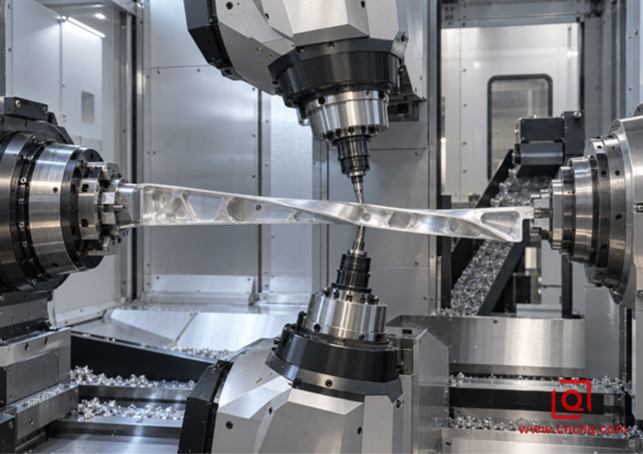
But a milling tooth enters, loads, and leaves. A moment later, another tooth takes its place. Sometimes the pulses oppose each other. Sometimes they gang up and the rib starts singing. The remaining wall also changes as pockets open and a taper gets thinner.
That makes cutter orientation, engagement, spindle phase, and collision simulation part of the process. A 2024 paper on twin-tool orientation smoothing for pinch milling is useful here: coordinated orientation is not a cosmetic CAM setting.
One flat on a shaft - would I pinch mill it? No. Usually not. A Y-axis turn-mill may cut the flat, slot, or cross hole while the turned datum is still sitting in the spindle. Liqin's Y-axis turning guide shows where live tooling already solves the job.
So the RFQ question becomes concrete. Does this weak section need an opposing cutter, or can one live tool keep the datum? Ask for the simulation and inspection route. The machine's axis count, by itself, is not an answer.
7. Failure Modes You Can Hear, See, and Measure
|
Symptom |
Likely mechanism |
First checks |
Corrective direction |
|
Diameter grows through the middle |
Net radial push-off remains too high |
Tool loads, unsupported span, center or rest position |
Improve local support or rebalance engagement |
|
Repeating lobes or alternating witness bands |
Tools are not sharing load consistently |
Center height, X offsets, nose radii, insert wear |
Requalify both stations and reduce mismatch |
|
Chatter appears only with both tools |
Dynamic coupling or cutter phase is unfavorable |
Turret stiffness, spindle speed, axial spacing, phase |
Change spacing or speed after stability review |
|
One chip stream wraps around the other tool |
Chip direction and coolant interfere |
Chipbreaker, nozzle aim, feed, tool orientation |
Separate chip paths before increasing removal |
|
Size is correct hot but wrong after release |
Thermal growth or elastic recovery |
Part temperature, clamp/support load, free-state measurement |
Stabilize and define acceptance condition |
|
Good turning, poor milled feature position |
Datum transfer or C/Y-axis setup error |
Work offset, spindle orientation, live-tool runout |
Probe and machine the feature in the same datum chain |
8. Inspection Must Match the Drawing’s Functional Intent
A slender part can change shape when the tailstock, steady rest, collet, or sub-spindle releases it. The drawing and quality plan should say whether acceptance occurs in a free state or under a defined functional restraint. Without that agreement, production and incoming inspection may both be internally consistent and still disagree.
For diameter, use a micrometer or appropriate comparator at defined axial stations and clocking angles. For straightness or total runout, support the part at drawing-relevant locations on centers or V-blocks and record the setup. For a milled flat, cross-hole, or fork, use a CMM or optical method tied to the turned datum axis. Surface texture should be measured with the specified cutoff and evaluation length rather than judged from shine.
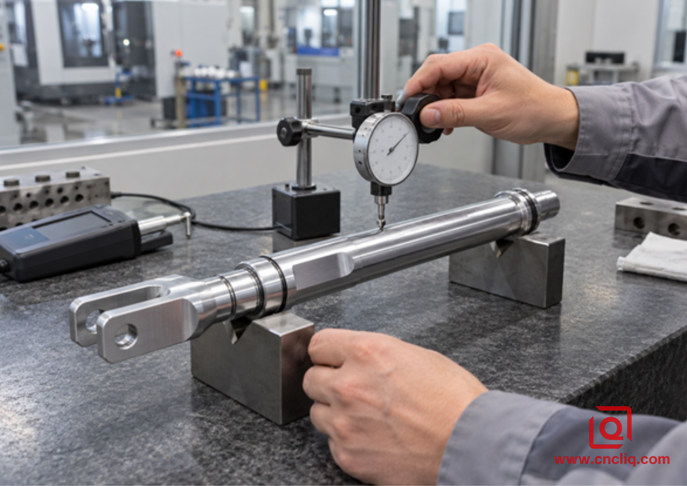
Liqin’s article on tight diameter tolerance in aluminum turning expands on temperature, clamping, gauge selection, and trend control. For a long shaft, also review the focused guide to preventing deflection in slender aluminum turning. These pages form a useful topic cluster: this article covers opposed-force machining, while the related guides cover single-tool support and diameter control in greater depth.
9. An Anonymized Composite Case: Lightweight Actuator Rod
The following is an anonymized composite DFM case built from common custom-machining conditions; it is not presented as a universal Liqin production result. A European automation-equipment buyer requested a 6061-T6 actuator rod with a long reduced center section, two seal journals, a milled fork, and a transverse pin hole. The drawing controlled the journal diameters, total runout to a primary datum axis, surface texture on the seals, and true position of the pin hole. Annual demand was high enough to justify a dedicated prove-out, but not high enough to justify a new forming die.
The initial route used single-tool roughing with a live center, followed by milling in a second machine. The shop trial identified three risks: the reduced middle span moved away from the roughing tool, the fork setup created a second datum chain, and long ribbon chips occasionally marked a finished journal.
The revised route kept a temporary support journal until late in the cycle. Matched opposed tools shared the open-diameter roughing stock. A single qualified edge then finished the seal journals under controlled support. The main spindle was oriented for live-tool milling of the fork and pin hole before the part left its turned datum. Chips were directed to opposite sides of the enclosure, and tool-life rules prevented one insert from remaining in service after its mate had been replaced.
Inspection did not rely on one end measurement. The quality team checked diameter at several axial stations, total runout on defined V-block locations after thermal stabilization, surface texture on each seal journal, and pin-hole position relative to the turned axis. The lesson was not that pinch turning “solved” the part. The win came from combining balanced roughing, one controlled finishing edge, retained support, same-datum milling, and free-state verification.
For buyers considering a comparable shaft family, Liqin’s listed custom precision gearbox output shaft shows the type of stepped shaft geometry, turning, milling, and inspection scope that should be discussed in a drawing-based quotation. Material and tolerances remain fully drawing-specific.
10. What to Put in the RFQ
A useful RFQ lets the supplier see flexibility, access, and acceptance conditions before pricing the cycle. Include:
1. A 3D model plus a controlled 2D drawing with revision status.
2. Complete material, temper, product form, and certificate requirements.
3. Minimum working diameter, overall length, and the maximum unsupported length created during each operation.
4. Datum definitions and the exact diameter, straightness, cylindricity, runout, profile, position, and surface-texture requirements that control function.
5. Whether center holes, temporary support journals, soft centers, steady-rest bands, or sacrificial tabs are allowed.
6. No-mark surfaces, cosmetic requirements, edge-break rules, coating or anodizing allowance, and protected threads or seals.
7. Annual volume, batch size, prototype quantity, target ramp, and whether traceable inspection data is required.
8. The requested inspection state, including temperature, support points, restraint, gauge method, and sampling plan.
9. Native CAD for any fork, flat, slot, cross-hole, or blade surface that may need live-tool or multi-axis milling.
10. Packaging and straightness-protection requirements for transport.
If you are unsure whether pinch machining is justified, send the drawing rather than prescribing a machine. Liqin can compare conventional supported turning, Swiss-style machining, mill-turn consolidation, pinch roughing, and specialist opposed milling around the actual tolerance chain. The guide to Swiss machining versus standard CNC turning for miniature aluminum shafts is a useful starting point when guide-bushing support may be more economical than dual-turret synchronization.
FAQs
1. Does pinch turning always eliminate deflection on a slender aluminum shaft?
No. It can reduce the net radial force when two tools engage at the same axial zone with closely matched geometry, offsets, wear, and chip load. The shaft can still deflect under residual imbalance, tangential and axial force, support misalignment, thermal growth, or vibration. Pinch turning should therefore be proved with load data and full-length measurement, not assumed from the presence of two turrets.
2. Is pinch turning faster than conventional single-tool turning?
It can be, especially during roughing, because two edges remove material simultaneously and balanced radial loading may permit a more productive stable cut. The real cycle gain depends on spindle power, turret limits, chip evacuation, approach time, synchronization, inspection, and tool-life management. For low quantities or rigid parts, the additional setup and prove-out can outweigh the cutting-time saving.
3. Should both tools finish the final diameter?
Not automatically. A matched opposed finish can help a long flexible diameter, but any difference in center height, insert radius, edge condition, or offset can influence form and size. Many robust plans use opposed tools for balanced roughing and reserve the final journal for one qualified edge under stable support. The drawing tolerance, span, machine condition, and process-capability study should decide.
4. Can a normal turn-mill center perform pinch milling?
Only if its physical configuration, control, CAM system, postprocessor, and collision model support two driven cutting stations acting on opposite faces at the required orientations. A machine with one live-tool turret and a sub-spindle can perform valuable same-datum milling, but that does not necessarily provide true pinch milling. Ask the supplier to explain the actual axis layout and simulation method.
5. What information most improves a quotation for a slender aluminum part?
Provide the 3D model and controlled drawing, complete alloy and temper, critical datum scheme, smallest diameter, unsupported span, geometric and surface requirements, permitted support features, finishing allowance, quantity, and inspection state. Those details let the supplier compare supported turning, Swiss machining, dual-turret pinch cutting, and mill-turn finishing without hiding uncertainty inside the price.
Summary
Pinch turning and pinch milling can make slender aluminum parts more stable by opposing the cutting loads that drive workpiece deflection, but the benefit appears only when machine layout, CAM synchronization, tool geometry, chip control, support, and inspection work as one system. Use balanced roughing where flexibility controls the process, choose the finishing strategy from the actual tolerance chain, and define free-state measurement before production begins. If your part combines long reduced diameters with flats, forks, slots, or cross-holes, submit the drawing and volume so Liqin can compare the safest single-setup route and provide a defensible quotation.
Contact Information
Company: Ningbo Liqin Industry Co., Ltd.Daily customer maintenance & after-sales support:service@shturl. zhuwanying@cncliq.com
New inquiry, quotation & order discussion:business@shturl. zhouli@chinaliqin.com
Hotline: +86 18757148656
Disclaimer
All technical articles, material specifications, machining recommendations, and surface treatment details published on this blog are for informational and reference purposes only. Please note that general blog insights do not replace signed technical agreements. Because custom parts vary by material heat numbers, machine calibrations, and specific tolerances, binding quality specs are governed solely by your approved CAD drawings, signed contracts, and formal quality plans.
All customer case studies featured on this blog have been thoroughly anonymized and sanitized. The performance metrics, manufacturing workflows, and imagery displayed serve solely to demonstrate our custom machining capabilities and do not represent a single universal standard for all orders.
Liqin Manufacturing Team
Built on 18 years of precision engineering experience, Ningbo Liqin Industry manufactures high-tolerance metal components for demanding global markets. We operate out of a 6,500 m² production hub equipped with over 150 machines, running 4-axis and 5-axis CNC machining, mill-turn machining, cold extrusion, and pressure die casting under one roof. This setup allows us to manage projects seamlessly, taking parts from initial CAD concepts directly to finalized shipments.
We handle quality control with zero compromise. We treat tight tolerances with the engineering discipline they require. Backed by ISO 9001, ISO 13485, and IATF 16949 certifications, our QA engineers run strict IPQC, FQC, and OQC checks on every single production batch. From CMM dimensional mapping and optical profiling to hardness and salt-spray testing, we validate your critical specs upfront—so you receive drop-in ready components with zero assembly headaches or costly line stoppages. On top of manufacturing, you can rely on us for two-hour response times on new RFQs, direct support for prototype sampling, and smooth export shipping across Europe, North America, Asia, and Oceania.
Welcome your inquiries and samples. Visit our website or contact us directly for a competitive quote!
