 English




Are you still fighting cloudy surfaces, drifting diameters, and silver material welded to the insert when a soft aluminum job should be the easy one? This guide explains what the machine is telling you, why built-up edge forms, and how to correct the process in a sensible shop-floor order. It is written for engineers, buyers, and machinists who need repeatable custom aluminum turning—not a magic speed copied from someone else’s lathe.
Quick answer: Built-up edge, or BUE, is workpiece material that adheres near the cutting edge and temporarily becomes part of the tool. In soft, ductile aluminum, it is encouraged by rubbing, a dull or unsuitable edge, excessive chip-to-tool contact, weak lubrication at the rake face, and recutting of stringy chips. Start by confirming that the defect is really BUE. Then restore a sharp polished aluminum geometry, keep the edge cutting rather than rubbing, direct clean lubricant to the chip–tool interface, and make speed or feed changes one variable at a time. Treat every number below as a commissioning range; the insert maker’s data and a controlled trial on the actual machine take priority.
1. What Built-Up Edge Looks Like—and Why Buyers Should Care
During turning, the chip slides across the insert’s rake face under high pressure. A small amount of ductile aluminum can adhere to that face, compact into layers, and grow at the cutting edge. The deposit changes the effective rake angle and edge radius. When it breaks away, part of it may travel with the chip; another fragment may be pressed into, or tear material from, the freshly turned surface. That grow–break–regrow cycle is why a part can look bright for several revolutions and suddenly develop a gray, smeared band.
This is more than a cosmetic fault. A false edge moves the point that actually contacts the workpiece, so a stable wear offset can become unstable. On sealing journals, optical barrels, pneumatic sleeves, and bearing fits, the practical consequences may include roughness spikes, diameter scatter, rolled burrs at grooves, unreliable probe readings, and extra polishing that rounds a controlled edge. The cost is not only an insert. It can be lost machine time, sorting, repeated first-article approval, and a late shipment.
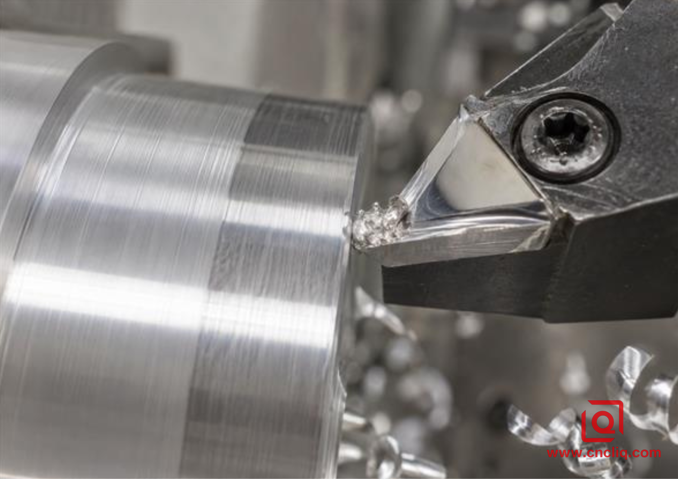
A small aluminum deposit alters the working edge before normal flank wear looks severe.
Do not confuse BUE with chatter. BUE usually leaves irregular smearing, torn patches, or random bright and dull areas. Chatter tends to leave a repeating wave pattern, often with a recognizable pitch around the circumference. A worn nose may give a broadly uniform loss of finish. Chip scratches usually follow the travel of a trapped chip. Stop the spindle safely, remove the insert, and inspect the rake face under magnification. A bright aluminum lump at the edge is strong evidence; a clean edge points the investigation toward rigidity, runout, coolant contamination, or workholding instead.
2. Why Soft Aluminum Can Be Harder to Turn Cleanly
Softness is not the same as easy chip control. Low-hardness, high-ductility aluminum can flow instead of fracture, creating a long chip with a large contact area on the rake face. If the edge begins to rub, local friction rises. The chip presses against the tool, adhesion starts, and the geometry deteriorates. A slow, cautious-looking pass can therefore be less stable than a decisive cut that forms a real chip.
Alloy and temper matter. Commercially pure aluminum, 3003, and annealed or lightly strain-hardened 5000-series material generally demand more attention to edge sharpness and chip control than a harder, stronger grade that breaks chips readily. Even within 6061, stock form, temper, extrusion history, and material lot can change the feel of a finish cut. Specify the complete alloy, temper, and stock form on the drawing; “aluminum” alone is not an adequate purchasing description. For a broader comparison, see Liqin’s OEM aluminum CNC turning and alloy selection guide.
An older but still useful NIST-hosted machining reference reports that, for many aluminum alloys, increasing cutting speed above roughly 30–60 m/min reduces the probability of BUE and improves chip breaking and finish. That is a physical trend, not a production recipe. Modern carbide and PCD tooling can run far faster, but a small diameter, spindle-speed ceiling, weak workholding, or interrupted feature may limit what the machine can use. The correct decision is to work from the tool supplier’s grade-specific window and verify the cut, not to chase a universal number.
3. The Four Control Levers: Edge, Chip, Lubrication, and Heat
Use an edge designed for non-ferrous work
A polished, sharp, positive-rake insert is the normal starting point for soft aluminum finish turning. Positive geometry lowers cutting force and shortens the chip–tool contact zone; a polished rake face gives the chip fewer microscopic sites on which to anchor. Generic steel inserts often have a stronger hone, a less-positive geometry, and a coating selected for hot ferrous cutting. They may survive, yet they can plough a soft aluminum surface instead of shearing it cleanly.
Uncoated polished carbide is a practical baseline. PCD can be attractive for a stable, high-volume finish operation because it offers a very hard, low-friction edge, but its higher tool cost only makes sense when the setup, allowance, interruptions, and expected batch size are controlled. Coating choice must come from the tool maker’s aluminum application data. Do not assume that a premium coating for steel is a premium choice for aluminum.
Give the chip enough thickness to leave
Feed that is too light relative to edge radius, runout, and machine condition can turn cutting into rubbing. On the other hand, feed that is too heavy may overload a slender part, exceed the chipbreaker’s range, or miss the roughness requirement. Think in terms of minimum effective chip thickness and chipbreaker function, not “slower is safer.” If the surface degrades after a feed reduction, inspect the edge before reducing feed again.
The ideal geometric roughness provides a useful sense check. For a round nose and small feed, theoretical peak-to-valley height is approximately Rmax ≈ f²/(8rε), where f is feed in mm/rev and rε is nose radius in mm. Real roughness will be worse when BUE, vibration, runout, material pickup, or chip scratching is present. The formula is not an acceptance prediction; it only shows why doubling feed has a strong geometric effect.
Lubricate where adhesion begins
For BUE control, fluid must reach the rake face and chip–tool contact zone. A large stream that hits the toolholder but misses the edge may cool the neighborhood without stopping adhesion. Aim a stable nozzle so the jet reaches the working edge before the chip shields it. Use a coolant or cutting fluid approved for aluminum and maintain it to the supplier’s concentration, pH, cleanliness, and water-quality limits. Concentration by appearance is guesswork; use a refractometer and the fluid maker’s correction factor.
Minimum-quantity lubrication can work on suitable, enclosed, risk-assessed processes, but it must supply enough lubricity at the edge and still move chips away. Dry air clears chips but contributes little boundary lubrication. For open manual machines, never improvise with flammable solvents. Follow the machine builder’s enclosure requirements, the fluid safety data sheet, fire controls, and local exposure rules.
Control heat without creating a new problem
Aluminum conducts heat well, yet the microscopic chip–tool contact still experiences pressure and friction. A blunt edge, dwell, poor chip evacuation, or repeated chip cutting concentrates heat exactly where adhesion starts. The goal is not simply “more coolant.” It is a sharp edge, correct chip load, reliable delivery, and a path for the chip to leave. An unstable trickle that alternately wets and dries an interrupted cut can also be less predictable than a deliberately qualified dry or fully flooded process.
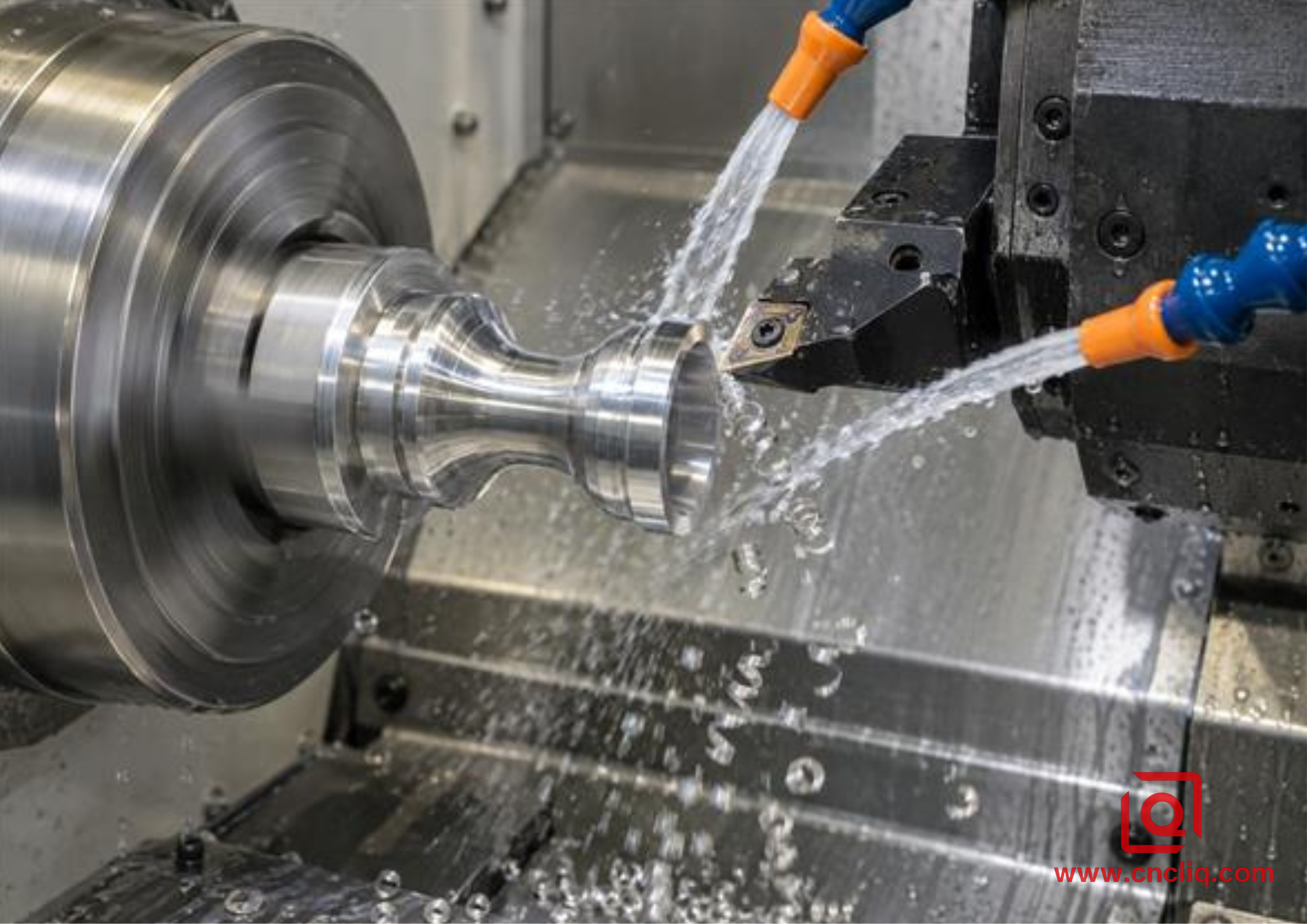
Directed flow reaches the edge and carries short chips away instead of merely washing the holder.
4. A Practical Starting Matrix for CNC Turning Soft Aluminum
The table below is a troubleshooting map, not a substitute for tool-maker data. Record the current condition before changing anything. If three variables move together and the finish improves, the shop still does not know which change fixed the problem or how much margin remains.
|
What you observe |
Likely mechanism |
First controlled action |
Evidence to record |
|
Random gray smears; bright aluminum on rake face |
Adhesive BUE and unstable false edge |
Install a fresh polished aluminum insert; verify nozzle aim |
Insert photo, roughness trace, diameter trend |
|
Finish worsens near center during facing |
Surface speed falls as diameter approaches zero |
Use qualified constant surface speed with a safe RPM limit |
Actual RPM, diameter where defect begins |
|
Long ribbon wraps around part or turret |
Chipbreaker outside its working range; ductile alloy |
Adjust feed within supplier range or select aluminum chipbreaker |
Chip shape and length, spindle load, safety stop count |
|
Regular waves but clean insert edge |
Chatter, overhang, weak clamping, or resonance |
Shorten tool/part overhang and check workholding first |
Wave pitch, overhang, jaw pressure |
|
Grooves and isolated scratches |
Chip recutting or bird nesting |
Redirect coolant/air and improve chip exit path |
Chip location, nozzle position, scratch direction |
|
Good first pieces, then sudden instability |
Progressive pickup, contamination, or edge damage |
Define an inspection/tool-change trigger |
Parts per edge, concentration, defect timing |
Use the standard turning-speed relationship to check whether the commanded value is physically possible: N = 1000Vc/(πD), where N is rev/min, Vc is m/min, and D is workpiece diameter in mm. For example, 300 m/min at 20 mm diameter requires about 4,775 rev/min. If the lathe is capped at 3,000 rev/min, the actual speed is about 188 m/min. This matters during facing and on small journals: the program may request an appropriate surface speed while the spindle limit quietly prevents it.
Shop-floor rule: Preserve a safe RPM ceiling in constant-surface-speed mode. Chuck rating, jaw engagement, bar condition, imbalance, and machine limits govern the ceiling; a surface-finish target never overrides them.
5. Troubleshoot BUE in a Fixed Order
1. Freeze the evidence. Save the last good part and first bad part. Photograph the insert before cleaning it. Record alloy and temper, material heat or lot, tool code, edge count, offsets, actual spindle speed, feed, depth of cut, coolant reading, and time in cut.
2. Confirm the failure mode. Look for adhered aluminum. Compare the surface with a magnifier and, when the print requires it, a calibrated roughness instrument. Do not diagnose BUE from a phone photo alone.
3. Restore the edge. Fit a new, verified insert for ISO N/non-ferrous material. Check seat cleanliness, screw condition, tool height, runout, and whether the insert has been used on another material.
4. Check fluid delivery and chip exit. Aim at the edge, not the holder. Remove packed chips from the enclosure and verify that the stream remains stable with the spindle running.
5. Check real cutting speed. Use the current diameter and actual RPM, especially on facing moves and small bores. If the process is below the tool maker’s range, raise speed in controlled steps within machine and workholding limits.
6. Check feed against the chipbreaker. A feed override that feels gentle may fall below the geometry’s useful window. Change one step at a time and examine chip form.
7. Check depth of cut and stock condition. A finish pass that barely touches an out-of-round or extruded surface may rub intermittently. Leave a deliberate, uniform finishing allowance after roughing.
8. Prove capability. Run enough consecutive parts to expose the grow–break BUE cycle. Measure size and roughness at defined intervals, not only the first piece.
This sequence avoids compensating for a damaged process with offsets. Liqin’s guide on machining 6061 aluminum with feeds, speeds, and tooling controls provides a complementary commissioning method, while the 3-axis, 5-axis, and mill-turn process selection guide helps when the part combines turned datums with cross-holes or milled flats.
6. Anonymous Case: Stabilizing a Soft-Aluminum Regulator Sleeve
The following is an anonymized, representative case constructed from common custom-machining conditions; the values illustrate the validation method and are not a universal promise. A fluid-control customer requested a pilot batch of 300 regulator sleeves from a soft 6000-series aluminum grade. Each sleeve had a 28 mm sealing diameter, two narrow O-ring grooves, and a bored pilot feature. The drawing called for the sealing diameter to remain within 0.020 mm total tolerance and for the turned surface to meet Ra 0.8 µm or better before cleaning.
The first setup produced acceptable dimensions on early parts, but later pieces developed cloudy bands. Operators reacted by reducing feed, then added a negative diameter offset. The surface became less consistent, and the offset concealed the real failure: aluminum had built up on a general-purpose coated insert. A long chip also brushed the finished journal before dropping into the conveyor.
The corrective trial changed the process in stages. First, the team replaced the insert with a polished positive-rake carbide geometry intended for aluminum and restored the programmed offset. Second, the nozzle was moved so fluid reached the rake face rather than the top of the holder. Third, constant surface speed was enabled with an RPM limit verified against the workholding. Finally, feed was set inside the chipbreaker supplier’s range and held constant through the critical journal. Roughing left a uniform 0.30 mm radial finishing allowance so the final pass remained a cut, not a polishing rub.
Validation used a 30-piece confirmation run. Diameter was checked at the front, middle, and rear of the journal; roughness was measured along the specified trace direction; and the insert was photographed after the run. The recorded results ranged from 0.006 mm to 0.014 mm total diameter spread and Ra 0.42 µm to 0.68 µm. Those results belong only to this illustrative setup. The important lesson is the method: diagnose the edge, change one mechanism at a time, and verify a sequence of parts rather than approving a single attractive sample.
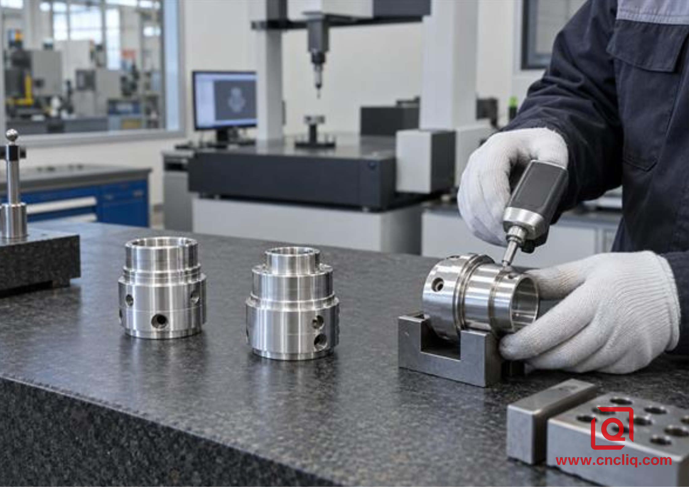
A stable process is released from measured trends, not from one visually bright component.
For comparable rotational parts, the same discipline applies to a precision aluminum motor flange and front end cap: the bearing bore and locating spigot need a clean, stable cutting edge before concentricity and surface requirements can be trusted. Cast and wrought aluminum behave differently, so parameters must still be qualified for the exact blank.
Planning a soft-aluminum turned part? Send the 2D drawing, 3D model, complete alloy and temper, annual quantity, critical-to-quality dimensions, roughness callouts, finish requirements, and inspection expectations. Liqin’s engineers can review tool access, finishing allowance, chip evacuation, and datum strategy before quotation. Request a manufacturing review and competitive quote.
7. What to Put in the RFQ So the Supplier Can Control BUE
A useful quote needs more than part weight and material family. State the alloy, temper, stock form, and applicable material specification. Mark the surfaces where appearance matters and the surfaces where roughness is functional. If Ra is required, define the value, evaluation direction when important, and whether it applies before or after anodizing or another finish. Identify mating diameters, seals, bearing fits, and datums. Give realistic prototype and production quantities; a PCD finish tool may be sensible for a recurring program and uneconomic for five development pieces.
Ask how the supplier will verify the process. A credible answer should connect the drawing to insert geometry, chip control, inspection method, and lot traceability. It should also explain what changes between first article and production, how tool-life limits are set, and which records can be supplied. If the answer is only “we use high speed,” the risk is still yours.
Also separate machining acceptance from final-part acceptance. A journal may pass after turning but change after surface treatment, cleaning, or aggressive manual polishing. Drawings should say whether coated dimensions are final, which areas require masking, and whether edges may be blended. This prevents a well-meant deburring step from damaging a seal land that the lathe produced correctly.
8. FAQ
1. Is built-up edge caused only by cutting too slowly?
No. Low surface speed can encourage BUE, but it is only one variable. A dull or heavily honed edge, unsuitable insert geometry, weak lubrication at the rake face, feed below the effective cutting range, chip recutting, and an inconsistent finishing allowance can all produce the same failure. Confirm adhered material on the insert, calculate actual surface speed at the problem diameter, and inspect fluid delivery before changing the program.
2. Should I use coated carbide, uncoated carbide, or PCD for soft aluminum turning?
Polished uncoated carbide is a sound starting point for many prototype and general-production jobs. An aluminum-qualified low-friction coating may help when the tool maker supports it for the alloy and operation. PCD can deliver long life and stable finish in high-volume, rigid, non-interrupted cuts, but it costs more and requires a justified tool-life study. Choose from supplier application data, not coating color or a steel-tool habit.
3. Why does the finish become worse when we reduce feed?
The lighter feed may be too close to the edge hone, nose condition, runout, or machine vibration, so the insert rubs and burnishes instead of forming a clean chip. Rubbing raises friction and can start aluminum adhesion. Compare the programmed feed with the insert maker’s chipbreaker range, inspect the edge for pickup, and adjust in small controlled steps while monitoring chip form, spindle load, size, and roughness.
4. Can coolant eliminate BUE by itself?
Coolant can reduce friction and move chips, but it cannot rescue a blunt edge or a rubbing cut indefinitely. Delivery is as important as volume: the stream must reach the rake face before the chip blocks it. Maintain an aluminum-compatible fluid to the manufacturer’s limits and keep the system clean. Pair fluid control with correct geometry, real cutting speed, feed, finishing allowance, and chip evacuation.
5. What information should an OEM send for a reliable aluminum turning quote?
Send the controlled drawing revision and 3D model; exact alloy, temper, and stock form; prototype and annual volumes; critical dimensions and datums; roughness and cosmetic zones; threads, grooves, and burr limits; final surface treatment; inspection documents; packaging needs; and delivery schedule. Highlight sealing and bearing features. These details let the supplier price the correct tooling, process validation, inspection frequency, and finishing route instead of adding a broad uncertainty allowance.
Summary
Built-up edge in soft-aluminum turning is an adhesion problem that quickly becomes a geometry, finish, and tolerance problem. Diagnose it at the insert, use sharp polished non-ferrous tooling, maintain a real chip instead of rubbing, deliver suitable lubricant to the rake face, clear chips, and verify actual surface speed across changing diameters. Change one variable at a time and release production from measured trends. That discipline produces a process an OEM can trust—and an RFQ a capable supplier can quote with less uncertainty.
Contact Information
Company: Ningbo Liqin Industry Co., Ltd.
Daily customer maintenance & after-sales support:service@shturl. zhuwanying@cncliq.com
New inquiry, quotation & order discussion:business@shturl. zhouli@chinaliqin.com
Hotline: +86 18757148656
Disclaimer
All technical articles, material specifications, machining recommendations, and surface treatment details published on this blog are for informational and reference purposes only. Please note that general blog insights do not replace signed technical agreements. Because custom parts vary by material heat numbers, machine calibrations, and specific tolerances, binding quality specs are governed solely by your approved CAD drawings, signed contracts, and formal quality plans.
All customer case studies featured on this blog have been thoroughly anonymized and sanitized. The performance metrics, manufacturing workflows, and imagery displayed serve solely to demonstrate our custom machining capabilities and do not represent a single universal standard for all orders.
Liqin Manufacturing Team
Built on 18 years of precision engineering experience, Ningbo Liqin Industry manufactures high-tolerance metal components for demanding global markets. We operate out of a 6,500 m² production hub equipped with over 150 machines, running 4-axis and 5-axis CNC machining, mill-turn machining, cold extrusion, and pressure die casting under one roof. This setup allows us to manage projects seamlessly, taking parts from initial CAD concepts directly to finalized shipments.
We handle quality control with zero compromise. We treat tight tolerances with the engineering discipline they require. Backed by ISO 9001, ISO 13485, and IATF 16949 certifications, our QA engineers run strict IPQC, FQC, and OQC checks on every single production batch. From CMM dimensional mapping and optical profiling to hardness and salt-spray testing, we validate your critical specs upfront—so you receive drop-in ready components with zero assembly headaches or costly line stoppages. On top of manufacturing, you can rely on us for two-hour response times on new RFQs, direct support for prototype sampling, and smooth export shipping across Europe, North America, Asia, and Oceania.
Welcome your inquiries and samples. Visit our website or contact us directly for a competitive quote!
