 English





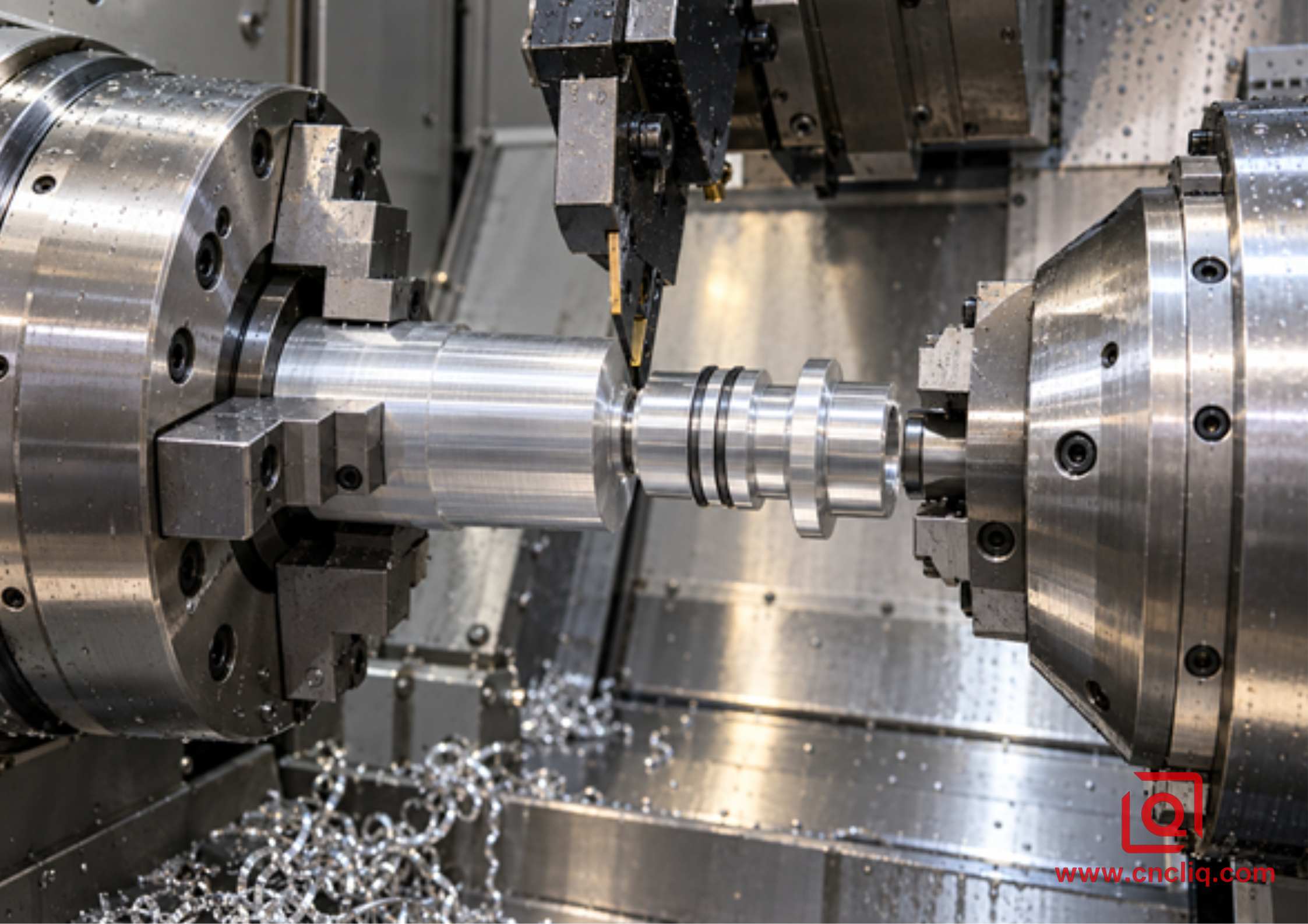
Turn the print around. The easy-looking sleeve now has a rear counterbore, a thread, and a seal face that still answer to the bore made from the front.
Complete parts dropping from one cycle are useful, but datum continuity is the stronger reason. It is not an accuracy button. The pickup land, jaws, cutoff stock, tool reach, chip path, and inspection routine still have to agree.
For the wider machine decision, see Liqin's comparison of CNC turning and turn-mill machining for concentric aluminum housings. This article stays at the handoff itself.
1. Inside the Handoff
Op 10 makes the accessible front geometry and leaves a deliberate landing place. The opposing chuck moves onto it; cutoff finishes; only then does the new holder of the part pull back for rear work. Three ordinary motions, and very little room for a casual assumption.
People call this done in one. Fair enough, although a transfer still occurs. A chip at the jaw or shallow contact can spoil that relationship before the rear tool cuts anything.
Control details are machine-specific. Haas Automation's secondary-spindle documentation discusses synchronized spindle control and spindle-swap functions on Haas controls. Autodesk's stock-transfer guide shows the CAM-side stages. Neither is a generic program for a different lathe. The builder manual, proven post, and actual tooling layout remain the authority.
A transfer review is easiest when it follows the part. Check the pickup land for usable length and honest jaw contact. Decide how relative spindle motion is prevented at closing. Trace cutoff stock to the rear facing pass and name the face that owns final length. Do not end the review at the last tool. Watch the first finished piece land; a bare steel catcher can add the only dent on an otherwise good component.
2. Aluminum Changes the Transfer Problem
A thin wall adds another trick: it may accept the chuck pressure, then change shape when released. It may measure one way while held and another after release.
The drawing, order, and certificate should agree. When 6061-T6, 6082-T6, or 7075-T6 is still being debated, Liqin's turning-alloy guide is the useful upstream read.
ISO N narrows the tool search; it does not finish it. Many wrought grades respond well to a keen positive edge and a polished rake face, yet the breaker still needs enough feed and depth to work. Prove speed, feed per revolution, coolant aim, and the RPM ceiling on the real stock. After the first piece, look at the edge as well as the finish. Silver material already stuck to the rake face is an early warning, however bright the diameter looks.
3. Find the Grip Before Writing the Toolpath
During DFM, circle the functional axis first. It may be a bearing bore, a locating pilot, a sealing diameter, or a thread. Next, mark the face that controls assembly length. Only then divide the features between spindles and reserve the pickup.
1. Name the datum used by the assembly. Do not let a convenient raw outside diameter quietly replace it.
2. Reserve a straight pickup land after chamfer, cutoff blade, and approach clearances are deducted.
3. Keep seal lands and cosmetic zones outside the grip where possible. If contact cannot be avoided, place the permitted band and appearance rule on the drawing.
4. Leave deliberate rear-facing stock. A cutoff witness is a starting condition, not a finished datum.
5. Trace the last chip before pickup. That chip matters more than a tidy chip pan after the batch.
6. Simulate both chucks, every jaw, the turret, full holder bodies, remaining bar, cutoff blade, finished part, and catcher.
7. Decide how the transfer will be checked. Looks seated is not an inspection method.
This map prevents a familiar quoting mistake. Live tooling, C-axis control, Y-axis travel, and a secondary spindle solve different geometry problems. Liqin's live tooling on CNC lathes guide explains the distinction. Ask for the actual configuration rather than the phrase mill-turn.
4. Grip the Land, Not the Bore
A good pickup leaves three things absent: slip, a jaw print, and a bore that changes after unclamping. On a thin sleeve, broad contact usually gives the process engineer more room than three narrow pressure points. Bored soft jaws can follow the pickup diameter; a suitable collet can support much of the circumference. Either method will misbehave if contact is dirty, tapered, or too short.
There is no universal chuck-pressure number for aluminum. Cylinder setting is only one input. Jaw mass, contact area, spindle speed, lubrication, wall stiffness, and the next tool's load all have a vote. A sensible prove-out starts low, checks for slip under the intended cut, records the accepted setting, and measures the released part. Copying a pressure from a steel shaft is not process control.
5. Treat Cutoff as Part of the Rear Operation
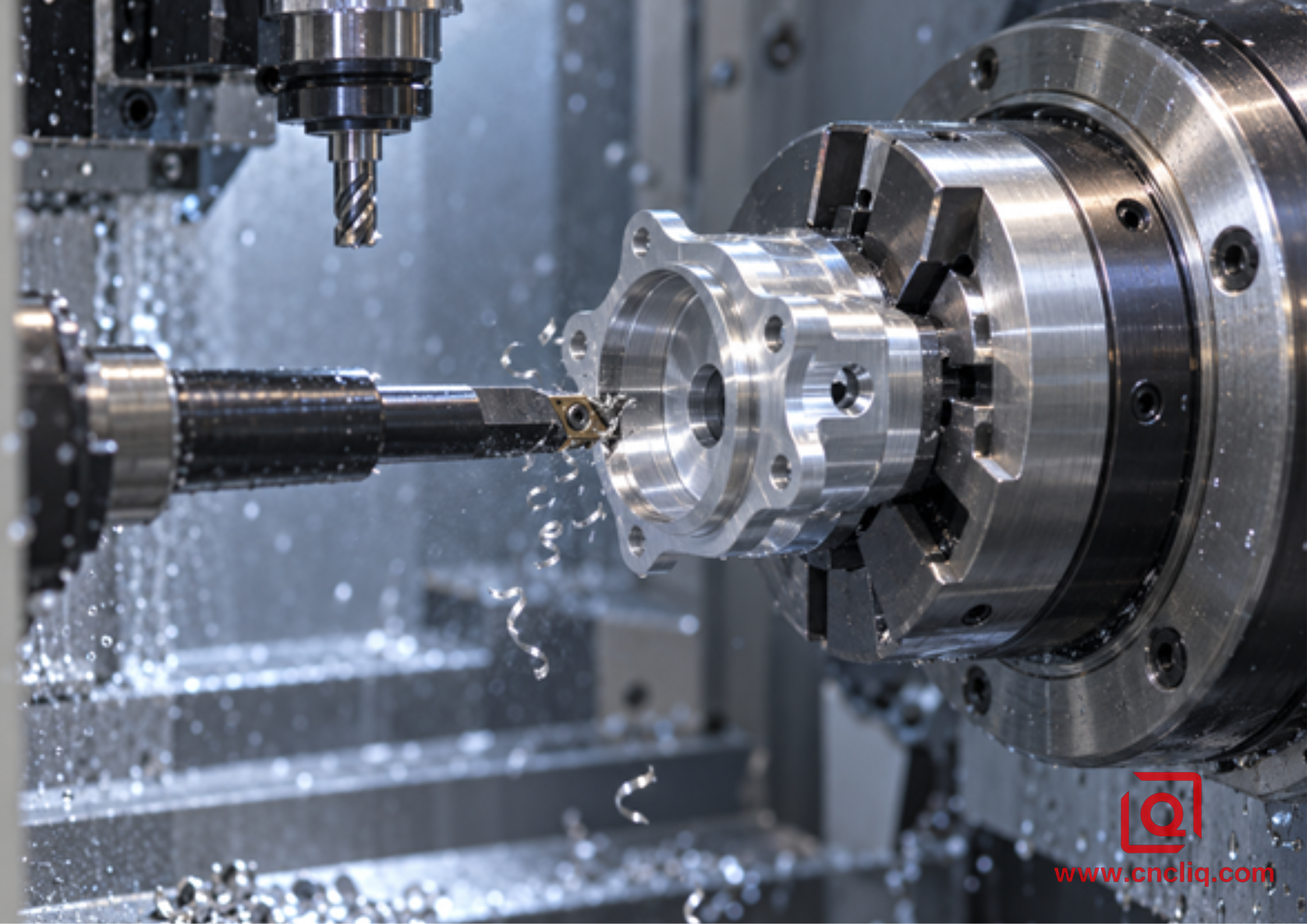
On a rotating handoff, both spindles must reach the commanded relationship before the second chuck closes and cutoff finishes. A small mismatch may scuff the pickup or lean on the parting blade. A stationary transfer has different rules for approach and orientation, but it still needs the machine's validated sequence.
Set the parting blade with the care normally reserved for a finish tool. Keep projection to what access needs, square the holder, confirm center height, and watch the chip as diameter disappears. The programmed surface speed may ask for more RPM near center than the workholding should see, so the cap matters. Liqin's aluminum grooving and parting guide covers the variables in more detail.
Once cutoff is clear, establish the back in the same way the setup sheet was proved. The first face pass has two jobs: erase the cutoff witness and create the axial reference for everything behind it. Overall length belongs on the released part, not on a dimension display while the wall is still under jaw load.
6. Let Wall Support Set the Order
Write the rear operations in pencil. A deep outside groove may need to wait until the bore is finished, simply because the wall is stiffer beforehand. A port that breaks into that bore argues the other way: make the breakthrough, then let a final boring cut take away the inward lip. The geometry, not a house template, settles the order.
Unattended time is won or lost in the chip path. Stringers near the tool can reach a chuck quickly. Start inside the insert maker's window and move only one lever at a time. Keep a quick record: chip shape, edge photograph, spindle load, and the same measured features on every trial. For the longer diagnostic trail, use Liqin's shop notes on aluminum chip control and built-up edge.
Tool reach matters on the back. Keep a boring bar as short and large as access allows. Before prove-out, read the posted code beside the simulation.
7. Read the Failure Before Moving an Offset
When a rear bore runs out, the offset page is tempting. Pause and indicate a known pickup surface first. If the component sits crooked, an offset can move the bore but cannot put the part straight in the chuck.
|
What the released part shows |
First things to inspect |
A useful check |
|
Oval or three-lobed grip area |
Jaw pressure, wall thickness, contact width |
Measure several angles after unclamping |
|
Rear feature runs out |
Chips, jaw taper, spindle alignment, slip |
Indicate a witness diameter, then verify the datum relationship |
|
Overall length walks |
Cutoff stock, stop contact, heat, offset ownership |
Trend rear stock and final length together |
|
Bright scratches |
Chip trapped at pickup or rough ejection |
Inspect the jaw print and catcher |
|
Rear bore chatters |
Bar overhang, weak grip, edge wear |
Measure at several depths and review tool load |
|
Thread gauges but will not assemble |
Burr, coating, relief, shoulder position |
Check the mating stack, not the thread alone |
A transfer fault and a cutting fault can resemble each other on one component. Review seating evidence, edge condition, machine temperature, and the gauge method before editing the program. One attractive sample is not proof; a short consecutive run shows whether the result repeats.
8. Inspect the Relationship That Justified the Sub-Spindle
First article should answer a functional question: did the rear geometry stay where the assembly needs it relative to the front? A list of isolated sizes cannot always answer that. Release the part before measuring a clamp-sensitive wall and use the datum reference frame on the controlled drawing.
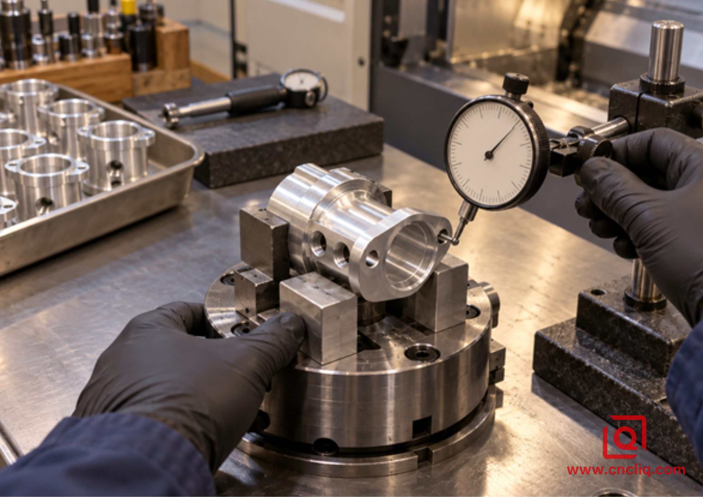
During setup, measure the released pickup diameter at several angles and relate a rear witness surface to the front datum using an indicator, a qualified mandrel, a dedicated gauge, or a CMM routine suited to the print. Overall length needs its own trend. A hidden breakout gets light, magnification, or a borescope after cleaning; an outside glance is not evidence.
Name the geometrical-tolerancing system on the print, whether ISO 1101 or ASME Y14.5. Then do the harder work: choose datums that reflect assembly, place finish and edge requirements where they matter, and say whether coating comes before or after the dimensional verdict. A standard explains symbols; it cannot choose the functional scheme for the designer.
Liqin's published precision motor flange and front end cap gives a verified product example: its bearing bore, locating spigot, and face make concentricity and perpendicularity important to assembly. The related servo motor front cover shows why circular interfaces and mounting features need targeted machining and inspection. These pages verify product scope; they do not promise one tolerance for every RFQ.
9. Sub-Spindle or a Separate Second Setup?
A second spindle is not the premium answer to every print. Ten simple prototypes may be calmer and cheaper in a carefully bored Op 20 fixture. The balance changes on a repeating sleeve whose rear seal pocket follows a front pilot. Compare fixture effort, handling, queue time, inspection, and rejected parts along with the minutes displayed on the control.
|
Decision point |
Sub-spindle route |
Separate Op 20 |
|
Datum relationship |
Strong when back features follow the front axis |
Sound when robust datums can be relocated repeatably |
|
Rear work |
Efficient for faces, bores, threads, grooves, and reachable driven-tool details |
Better for broad milling or features the turret cannot reach |
|
Batch behavior |
Favors repeated complete-part cycles |
Often sensible for prototypes and short runs |
|
Main risk |
Pickup contact, chips, limited space, collision |
Manual handling, second fixture, queue, relocation error |
The broader comparison in choosing the right CNC process for custom aluminum parts helps when the choice also includes 3-axis or 5-axis machining.
10. Anonymous Composite Case: Aluminum Pneumatic Regulator Sleeve
This is a composite shop case based on ordinary machining conditions and Liqin's published CNC scope. It is not an identifiable customer's production record and does not promise the same result on a new drawing.
An industrial automation RFQ calls for a 6061-T6 regulator sleeve with a front pilot, slim sealing bore, two outside O-ring grooves, one offset radial port, and a rear internal thread. The rear shoulder controls assembly length. The port has to break into the bore without leaving a loose lip.
The early route uses a conventional lathe followed by a manual second operation. It can make every feature, but the operator must grip a finished thin wall for the rear thread. Op 20 also references the outside diameter even though the bore is the functional axis. That combination invites jaw distortion, chip marks, and inconsistent pilot-to-rear-bore runout after release.
The revised concept reserves a dedicated pickup land. Broad-contact soft jaws are bored to that diameter and force is qualified through trials rather than copied from another job. The main spindle completes the front pilot, rough bore, outside grooves, and radial port. The secondary spindle receives the component, cutoff leaves planned facing stock, and the rear face becomes the axial reference for the shoulder and thread.
The setup team checks the blue contact pattern in the soft jaws before heavy rear work. Contact only at the jaw mouth would expose a bell-shaped grip. A broad pattern allows the prove-out to continue. The operator then faces the rear, pauses, and indicates the transfer witness before committing to the bore and thread.
One sequencing detail matters. The radial port has already broken into the sealing bore. Leaving controlled stock for the last boring pass lets that pass remove the fine inward lip. The final pass is not merely chasing size; it leaves a clean intersection and a trustworthy sealing surface.
Inspection follows the same logic. The sleeve comes out of the jaws before the bore is judged. Length is taken from the functional front face. Setup checks cover jaw contact and the transfer witness; production inspection covers the drawing characteristics at the agreed frequency.
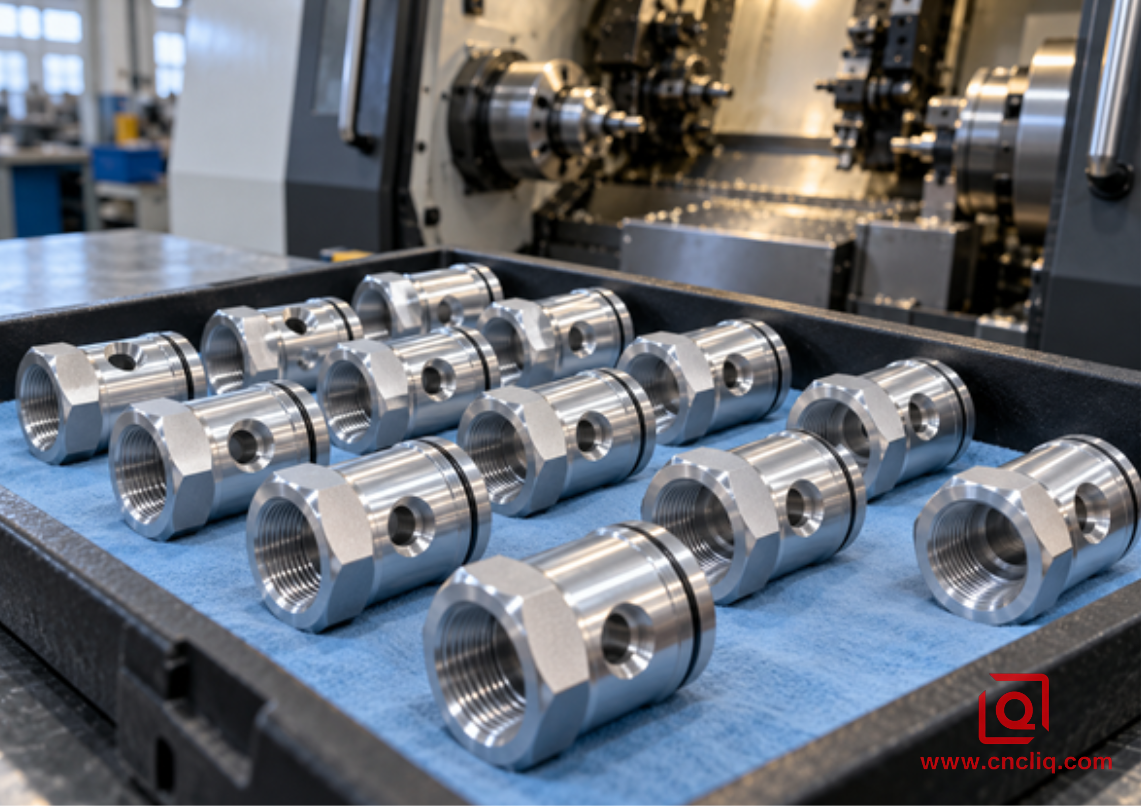
The commercial gain is quieter than a heroic cycle-time claim: one less manual re-clamp, less work waiting between operations, and measurements tied to assembly function. Any real cycle, capability, tool-life, or acceptance figure would have to come from the approved material heat, named machine, released drawing, sample size, and control plan.
11. An RFQ Checklist From the Other Side of the Desk
A useful quote package answers the awkward questions before an estimator has to email them back. The model shows shape. The print says what must be true. The short note in the email explains why. When those three agree, routing gets quicker and commercial padding usually gets smaller.
1. Model and print, both current. STEP is ideal for the solid; the controlled PDF or CAD drawing owns dimensions, GD&T, threads, finish notes, and acceptance. Put the revision in the filename and in the order. It sounds fussy until two nearly identical files land in one inbox.
2. Material without shorthand. State alloy, temper, and stock form, then say whether alternatives may be proposed. Add the certificate level you need. The word aluminum by itself does not tell purchasing what to buy.
3. Real quantities. Separate prototype pieces, the first release, annual demand, and the usual call-off size. A shop may machine twenty pieces with simple jaws and tool two thousand pieces very differently.
4. One sentence about function. Which bore guides a bearing? Which face seals? Does the thread see repeated service? A little assembly context can change the pickup surface, operation order, and gauge choice.
5. The finish as a process, not a color name. Include anodize or coating type, masking, controlled thickness, appearance zones, and the stage at which dimensions apply. If a sample chip or color range governs, include that fact.
6. Burr and cleaning expectations. Circle buried intersections, blind bores, and fluid paths, then describe what cannot remain.
First article, CMM layout, material certificate, capability data, gauge study, or a customer template all take time. Ask early and the quote can carry that time honestly.
8. Enough mating geometry to explain the fit. A cropped interface model or section view is often sufficient. Protect unrelated design information while giving the process engineer the surfaces that drive assembly.
12. What the Buyer Should Ask
So ask about the route. Where is the pickup? What establishes rear length? How is a chip kept out of the jaws? Which measurement proves the back still belongs to the front?
For a DFM review, send Liqin the current model and print, material, finish, quantities, and the required date.
FAQs
1. Does the second spindle remove setup error?
During prove-out, indicate a known pickup surface before the heavy back work begins. After release, inspect from the drawing datums. A transfer that finishes without an alarm has passed a safety milestone, not a dimensional inspection.
2. What pickup length should I allow?
There is no honest one-number answer. A solid plug, a thin sleeve, and a long overhung housing can share a diameter yet need very different support. Check grip on the real section view, not on a ratio chart. A stubby plug will tolerate what a thin sleeve will not. Mark the straight contact land, subtract its chamfer and tool clearance, and have the supplier prove what remains with the intended jaws, spindle speed, and heaviest rear cut.
3. May the jaws touch a finished outside surface?
Sometimes the finished diameter is the only practical pickup land. Broad-contact bored soft jaws, a suitable collet, a clean interface, and proven force help limit marking. Put the permitted contact band and the viewing standard on the print; keep seal lands and fragile coated areas outside it when the geometry gives you that option.
4. When is back-working cheaper?
Compare the cost of accepted parts. That comparison includes tooling, setup labor, waiting, measurement, handling, and realistic yield, not just the green-light cycle.
5. What should the drawing make obvious?
Name the rotating or assembly axis, the face that controls length, and every surface the second chuck may touch. Add rear-feature tolerances, complete thread data, burr limits, and the coating condition. A small mating section or one sentence about assembly often settles the remaining doubt.
Summary
That result comes from a clean contact land, sensible jaws, controlled cutoff stock, reachable tools, chip discipline, and inspection that follows the assembly.
Contact Information
Company: Ningbo Liqin Industry Co., Ltd.Daily customer maintenance & after-sales support:service@shturl. zhuwanying@cncliq.com
New inquiry, quotation & order discussion:business@shturl. zhouli@chinaliqin.com
Hotline: +86 18757148656
Disclaimer
All technical articles, material specifications, machining recommendations, and surface treatment details published on this blog are for informational and reference purposes only. Please note that general blog insights do not replace signed technical agreements. Because custom parts vary by material heat numbers, machine calibrations, and specific tolerances, binding quality specs are governed solely by your approved CAD drawings, signed contracts, and formal quality plans.
All customer case studies featured on this blog have been thoroughly anonymized and sanitized. The performance metrics, manufacturing workflows, and imagery displayed serve solely to demonstrate our custom machining capabilities and do not represent a single universal standard for all orders.
Liqin Manufacturing Team
Built on 18 years of precision engineering experience, Ningbo Liqin Industry manufactures high-tolerance metal components for demanding global markets. We operate out of a 6,500 m² production hub equipped with over 150 machines, running 4-axis and 5-axis CNC machining, mill-turn machining, cold extrusion, and pressure die casting under one roof. This setup allows us to manage projects seamlessly, taking parts from initial CAD concepts directly to finalized shipments.
We handle quality control with zero compromise. We treat tight tolerances with the engineering discipline they require. Backed by ISO 9001, ISO 13485, and IATF 16949 certifications, our QA engineers run strict IPQC, FQC, and OQC checks on every single production batch. From CMM dimensional mapping and optical profiling to hardness and salt-spray testing, we validate your critical specs upfront—so you receive drop-in ready components with zero assembly headaches or costly line stoppages. On top of manufacturing, you can rely on us for two-hour response times on new RFQs, direct support for prototype sampling, and smooth export shipping across Europe, North America, Asia, and Oceania.
Welcome your inquiries and samples. Visit our website or contact us directly for a competitive quote!
