 English




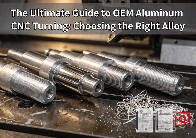
1. The Hidden Friction in "Easy" Aluminum Turning
When an engineering drawing lands on our machining bench with a generic note like "Aluminum Material: TBD" or "Commercial Grade Al," cutting tools are about to pay the price. Or your finished unit price will. Turning aluminum on a CNC lathe always reads easy on a process sheet. The material cuts fast, letting you crank the spindle to 4000 RPM, douse the turret with an 8% semi-synthetic water-soluble emulsion, and let sharp carbide inserts shear through stock at aggressive cycle times.
Then bird-nesting hits. A stringy, unbroken knot of silver swarf binds around the boring bar, gouges the finished inner bore, deflects the insert tip by 0.04 mm, and scraps a dynamic seal face before the inspection probe even drops.
[Spindle / Chuck] ===> [Workpiece: Turned OD] <--- [PCD / Polished Carbide Insert]
                                  |
               Long Stringy Swarf / Bird's Nesting
               (Wrong Alloy / Chipbreaker Mismatch)
                                  v
              Scratched Sealing Surface (Ra > 1.6 µm)
2. Why Chip Mechanics Matter More Than Tensile Strength
Selecting the right grade for custom turned components is never just an ASTM material chart exercise. It is a live shop-floor decision connecting bar stock machinability, cutting pressure, spindle harmonics, tool life, thread crest integrity, and secondary surface finishing.
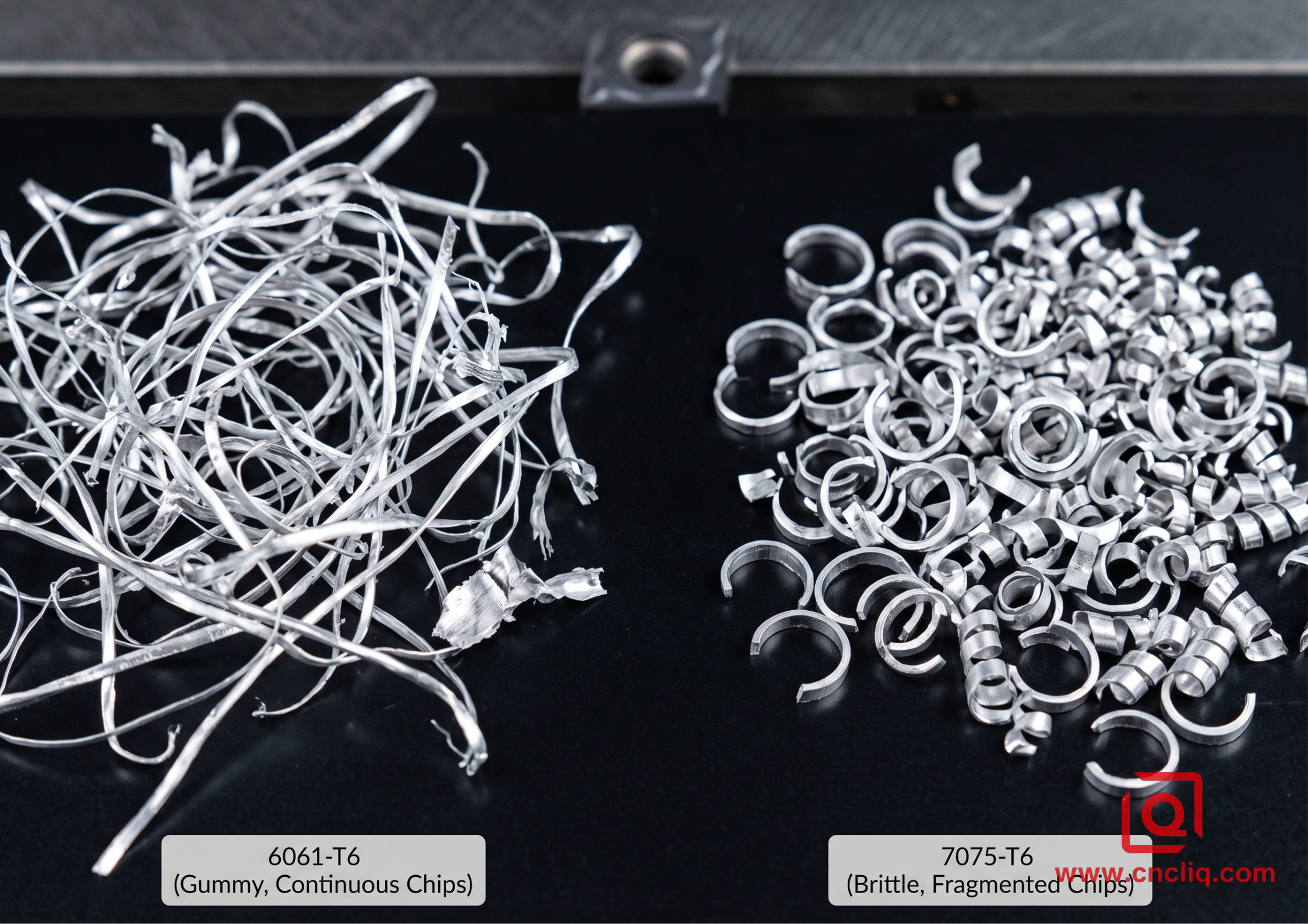
Tensile strength does not dictate lathe performance; chemical composition, temper condition, and chip formation mechanics do. When turning cylindrical stock, workpieces generate constant friction along the tool's rake face. If an alloy lacks brittle intermetallic phases, the chip refuses to fracture against the insert breaker pocket. Instead of snapping into clean segments, the hot metal flows, smears, and friction-welds itself onto the cutting edge to create a built-up edge. Once this occurs, your insert is no longer shearing material cleanly; it is plowing through stock. Diametral tolerances immediately drift outward by 0.03 mm or more, while surface finishes degrade from a smooth Ra 0.8 µm down to a torn, cloudy Ra 3.2 µm.
| Alloy & Temper | International Standard | Chip Formation Behavior | Turning Machinability | Typical OEM Applications |
| 6061-T6 / T651 | ASTM B221 / UNS A96061 | Continuous ductile ribbon; requires positive breaker | Moderate; gummy below 350 m/min | Fluid fittings, valve blocks, sensor housings |
| 7075-T6 / T651 | ASTM B211 / UNS A97075 | Short, brittle "C" shapes; fractures effortlessly | Superior; minimal tool pressure | High-stress shafts, aerospace sleeves, pistons |
| 2024-T351 | AMS 4120 / UNS A92024 | Tight spiral curls; highly predictable shear line | Outstanding; yields ground-like surfaces | Precision bushings, armature shafts, guide pins |
| 6082-T6 | EN 755 / EN AW-6082 | Stiff curly chips; mildly abrasive to tool flanks | Good; requires targeted high coolant flow | Marine mechanical hardware, heavy machinery pins |
3. Shop-Floor Breakdown: Machining Four Major Aluminum Grades
-
6061-T6: The Universal Workhorse and Its Gummy Limitations
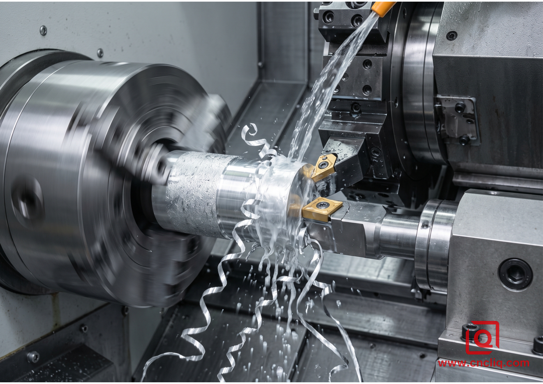
Every purchasing department loves 6061. It is readily available in cold-finished and extruded bars, welds easily, and takes decorative color anodizing per MIL-A-8625 Type II without blemish. However, extruded 6061-T6 bar stock reveals a soft, gummy nature during turning passes. If cutting speed drops below 350 m/min—such as when facing down toward the center line of a small shaft where spindle RPM hits machine limits—the metal stops shearing cleanly and begins tearing.
To run 6061 smoothly, machinists must steer clear of general-purpose coated carbide inserts designed for steel, relying instead on mirror-polished, uncoated micro-grain carbide inserts ground with positive rake angles between 12 and 18 degrees. Finishing feeds need to stay between 0.08 mm/rev and 0.12 mm/rev, because dropping below 0.05 mm/rev causes the insert edge to rub and burnish rather than cut, introducing work-hardening and micro-chatter across the workpiece.
[Tool Turret]
      |
      +---> Roughing: CCGT / WCGT Insert (Uncoated ground carbide, nose radius 0.8 mm)
      |
      +---> Finishing: Polished PCD (Polycrystalline Diamond) Tip, nose radius 0.4 mm
               |
               +---> Delivers consistent Ra 0.4 - 0.8 µm across 5,000+ parts
-
7075-T6: Maximum Rigidity and Free-Cutting Precision for Deep Threads
If your priorities are rapid cycle times, clean thread profiles, and dimensional repeatability across thousands of parts, 7075-T6 easily outperforms 6061. The high zinc matrix acts almost like brittle chalk against a sharp insert nose. At feeds around 0.18 mm/rev, chips snap into tight curls that drop straight down into the chip conveyor without tangling around live tooling blocks. When single-pointing deep internal threads, such as an M12x1.0 bore, 7075 delivers sharp, burr-free crests that eliminate secondary deburring. Corrosion resistance is the real penalty here. Without the built-in weather protection of 6000-series stock, 7075 demands immediate surface passivation right off the spindle—usually a 50 µm MIL-A-8625 Type III hardcoat sealed in nickel acetate.
-
2024-T351 & 6082-T6: Slender Shaft Stability vs. Structural Wear Resistance
Long, slender drive shafts needing concentricity dialed within 0.015 mm total indicator reading pose a different trap: standard 6061 bar stock tends to banana once roughing passes unleash locked-in extrusion stresses. Switch to 2024-T351. Packed with copper, it shears cleanly across broad thermal swings, pulling Ra 0.4 µm straight off the insert. Just remember the catch: that same copper turns parts into a muddy, blotchy mess in the anodizing bath, so keep it off any BOM that demands clean cosmetic color.
Meanwhile, drawings originating from European engineering teams regularly specify EN AW-6082-T6. While mechanically equivalent to 6061 in strength, its higher manganese content between 0.40% and 1.0% makes chips stiffer and more abrasive to cutting inserts, causing flank wear to advance 20% faster and requiring through-tool coolant directed at 20 bar pressure right into the cut zone.
4. OEM Case Study: Eliminating Leakage in a Marine Actuator Plunger
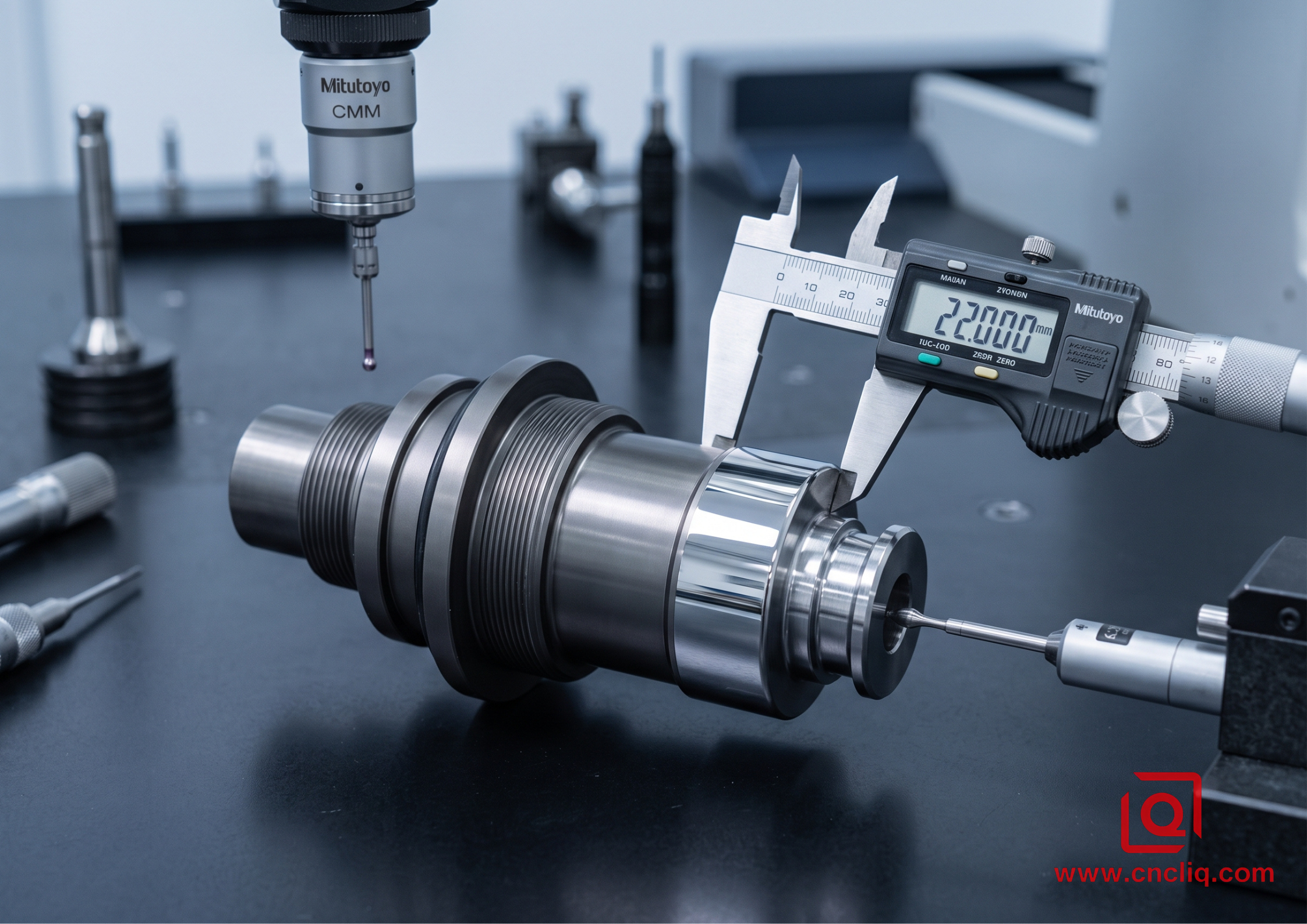
A marine fluid-power OEM client recently approached us to manufacture a high-pressure actuator plunger. The raw stock started as a 45 mm diameter cold-drawn round bar, designed into an overall component length of 142 mm. The critical feature was a 22 mm diameter dynamic sealing journal extending across a 45 mm length, carrying a tight tolerance of +0.000 / -0.012 mm, a strict surface requirement of Ra 0.4 µm max to seal against a hydraulic U-cup, and an operating duty requirement of holding 210 bar pressure in offshore saltwater.
The client's initial drawing specified 6061-T6 with a standard 10 µm clear anodize layer. During our initial 50-piece prototype run, peeling 45 mm stock down to a 22 mm journal released severe internal residual stresses, throwing the shaft out of alignment with an average runout of 0.028 mm across the journal length—nearly triple the allowable 0.010 mm limit. Furthermore, microscopic tearing appeared on the sealing diameter despite running diamond-like carbon coated inserts at 600 m/min. The contact profilometer wavered between Ra 0.6 µm and 0.8 µm, and the dynamic rubber lip seals failed pressure-hold validation under 210 bar.
Profilometer Trace Comparison:
6061-T6 Journal : ~~~^~~^v~~^~~~  (Ra 0.72 µm, localized micro-tearing) -> FAILED
6082-T651 Journal: ----------------  (Ra 0.31 µm, uniform shear plane)   -> PASSED
Instead of fighting the material with secondary cylindrical grinding, we corrected the issue at the source by restructuring the production strategy:
-
Alloy and Temper Upgrade: We changed the raw material to EN AW-6082-T651 stress-relieved round bar, where the mechanical stretching process locks internal stresses in place so shafts remain perfectly straight after deep roughing.
-
Two-Stage Machining Cycle: We rough-turned the diameter down to 23.2 mm using a polished CCGT insert at 420 m/min and 0.25 mm/rev, inserted a 12-second high-pressure coolant wash to normalize component temperature at 22°C, and then made a final 0.6 mm radial finishing pass using a Polycrystalline Diamond (PCD) insert at 720 m/min and 0.07 mm/rev.
-
Dimensional Allowance for Hardcoat: We switched the surface treatment to a 25 µm non-dyed MIL-A-8625 Type III hardcoat anodize impregnated with PTFE, machining the seal journal 0.012 mm undersized per side on the lathe to account exactly for the 50% surface penetration and 50% outward build-up.
This adjustment stabilized the turned journal surface between Ra 0.28 µm and 0.34 µm straight off the machine, while total indicator runout stayed securely under 0.006 mm throughout the entire 10000-piece production run. Every actuator plunger passed qualification pressure testing without a drop of leakage.
5. The Pre-Production RFQ Checklist for Turned Aluminum Components
Before releasing an RFQ package or manufacturing print for OEM turned components, always audit the callouts. Specify full temper designations rather than generic grades, noting "6061-T651" rather than just "6061" to guarantee bar stress relief. Lock down whether print tolerances apply pre- or post-plate, especially once heavy builds like Type III hardcoat enter the mix. Tightening finish callouts past Ra 0.4 µm? Swap gummy 6061 for free-machining stock like 7075-T6 or 6082-T6 so you skip bench polishing entirely. Finally, size the fattest shaft shoulder right to standard off-the-shelf bar stock—think 25 mm, 32 mm, or 50 mm. You will slash both roughing cycles and wasted drop.
FAQs
Q1: Why does 6061 aluminum often develop a cloudy, torn finish during CNC finish turning?
A: That milky, dragged surface rarely points to loose machine iron; 6061 simply runs soft and gummy. As your tool faces in toward part centerline, surface footage plunges. Starved of speed, the heated stock stops shearing cleanly and cold-welds straight onto the carbide tip, building an edge. From that point on, you are dragging a blunt wedge instead of cutting metal. To beat this, push constant surface speed (CSS) all the way into center, swap to high-rake polished inserts with up to 18 degrees of positive hook, and keep feed pressure steady so the edge cuts clean instead of rubbing.
Q2: What is the practical machining difference between 6061-T6 and 6061-T651 round bar?
A: Both grades carry identical chemistry and tensile numbers, but they behave nothing alike once skin cuts come off. Standard T6 bar holds heavy residual quench stress just beneath its mill skin. Hog off one side or turn a deep step on an engine lathe, and those uneven forces release at once, bending long shafts like banana peels. T651 stock gets pulled on a stretcher for a permanent 1% to 3% elongation right after the quench tank. That mechanical pull knocks out trapped core tension, meaning parts stay dead flat and straight through heavy hogging passes.
Q3: Can turned 7075-T6 parts be color-anodized alongside 6061 components in the same assembly?
A: You can dip them in the exact same chemistry line, but they will never match by eye. The heavy zinc and copper that give 7075 its raw strength also dirty up the transparent aluminum oxide matrix. Where 6061 pulls crisp, saturated color out of common dye tanks, 7075 generates a murky, brassy tint underneath. Color dyes end up dingy, gray-shifted, and noticeably dark. When exterior covers need a uniform hue, keep all cosmetic covers in 6061. If high loads force you into 7075, run a matte black dye or skip color completely with a raw hardcoat.
Q4: How should part drawings account for Type III Hardcoat Anodize dimensional growth on turned diameters?
A: Plating piles material on top; hardcoat actually eats base metal to grow an aluminum oxide skin. That growth splits right down the middle—half penetrates into the core, and half extends outward past your original turn line. For a 25 µm hardcoat spec, the OD swells by roughly 0.025 mm across the full diameter. Prints have to state whether tight shaft limits apply before or after treatment. If dimensions dictate final pre-assembly size, turn critical bearing journals slightly under so fits do not bind up tight at final build.
Q5: When does an OEM component justify switching from standard 6061-T6 to 2024-T351 or 6082-T6?
A: You pull the trigger on an alloy swap when 6061 hits its physical ceiling. Pick 2024-T351 for tight pins, transmission components, and precision spuds because its copper content breaks chips cleanly without bird-nesting, letting you pull ground-grade surface finishes directly off the insert without lapping—assuming you can live without bright color anodizing. Turn to 6082-T6 for structural housings, marine linkages, and heavy hydraulics. Its manganese backbone tacks on 10% to 15% more yield strength than 6061 and shrugs off saltwater pitting under high pressure.
Summary
Dialing in aluminum stock for OEM lathe work comes down to balancing cutting ease, core stress, and secondary finishing. While 6061-T6 stays the reliable go-to, its stickier shear mechanics require tight feeds, high SFM, and aggressive chipbreakers to dodge built-up edges or torn surfaces. When running high-volume jobs that need crisp, durable threads, 7075-T6 snaps chips cleanly and resists burring. For skinny shafts that cannot tolerate runout and still demand mirror finishes near Ra 0.4 µm, pre-stretched 2024-T351 and EN AW-6082-T651 stop raw stock from bowing, dodging bench straightening or secondary grinding. Practical DFM steps—calling out true temper designations, sizing for 50-50 anodize buildup, and choosing near-net bar diameters—hold tight prints, seal faces flat, and keep part costs right on target straight off the spindle.
Contact Information
Disclaimer
All technical articles, material specifications, machining recommendations, and surface treatment details published on this blog are for informational and reference purposes only. Please note that general blog insights do not replace signed technical agreements. Because custom parts vary by material heat numbers, machine calibrations, and specific tolerances, binding quality specs are governed solely by your approved CAD drawings, signed contracts, and formal quality plans.
All customer case studies featured on this blog have been thoroughly anonymized and sanitized. The performance metrics, manufacturing workflows, and imagery displayed serve solely to demonstrate our custom machining capabilities and do not represent a single universal standard for all orders.
Liqin Manufacturing Team
Built on 18 years of precision engineering experience, Ningbo Liqin Industry manufactures high-tolerance metal components for demanding global markets. We operate out of a 6,500 m² production hub equipped with over 150 machines, running 4-axis and 5-axis CNC machining, mill-turn machining, cold extrusion, and pressure die casting under one roof. This setup allows us to manage projects seamlessly, taking parts from initial CAD concepts directly to finalized shipments.
We handle quality control with zero compromise. We treat tight tolerances with the engineering discipline they require. Backed by ISO 9001, ISO 13485, and IATF 16949 certifications, our QA engineers run strict IPQC, FQC, and OQC checks on every single production batch. From CMM dimensional mapping and optical profiling to hardness and salt-spray testing, we validate your critical specs upfront—so you receive drop-in ready components with zero assembly headaches or costly line stoppages. On top of manufacturing, you can rely on us for two-hour response times on new RFQs, direct support for prototype sampling, and smooth export shipping across Europe, North America, Asia, and Oceania.
Welcome your inquiries and samples. Visit our website or contact us directly for a competitive quote!
