 English




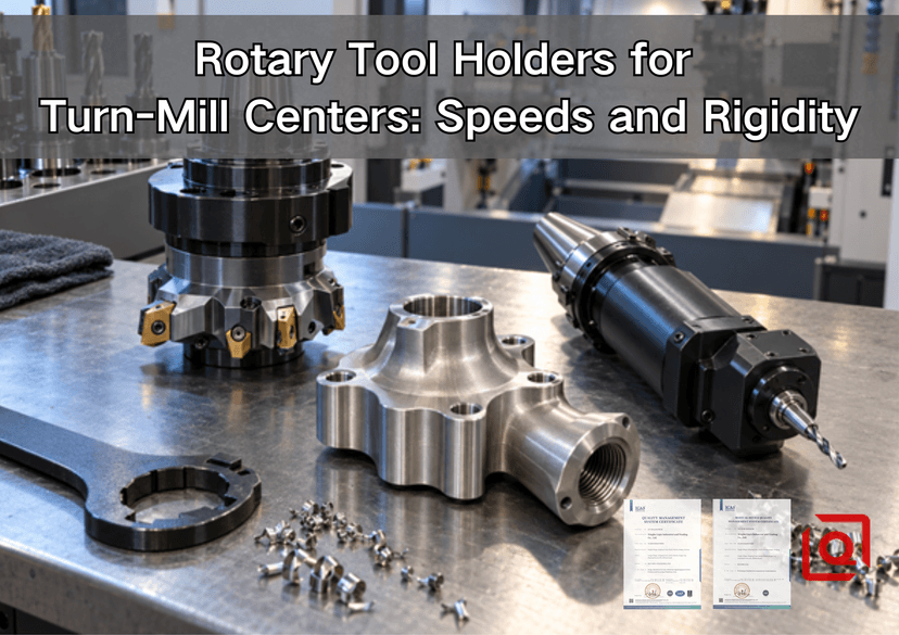
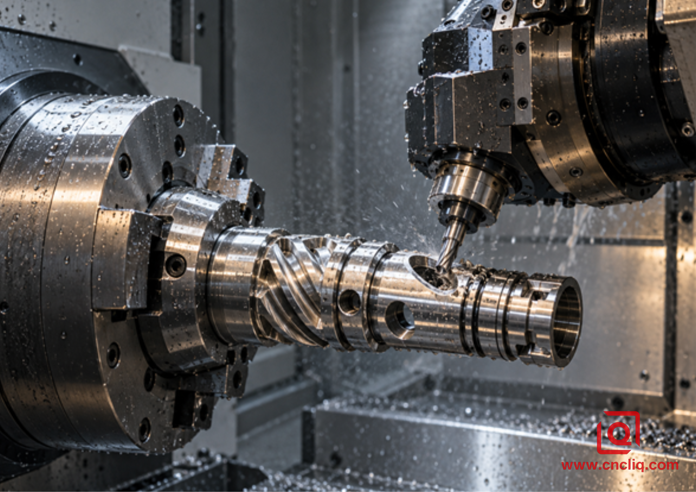
Ever heard a live tool begin to sing halfway into a slot, even though the programmed speed looked perfectly reasonable? That sound is usually the shop’s first warning that the number on the screen and the capacity at the cutting edge are not the same thing. A catalog can tell you a maximum rpm. It cannot see the long end mill, the warm bearing set, the slightly tired collet, or the jaw corner that forced the programmer to add another 18 mm of reach.
That is the problem this article tackles. We will work from the cut back through the holder, turret, and machine instead of starting with the biggest number in a specification table. The aim is practical: stable holes, flats, slots, ports, and threads on parts that also carry critical turned diameters. Buyers will also see which details belong in an RFQ, because “use live tooling” is not a process plan.
1. What a Rotary Tool Holder Actually Does
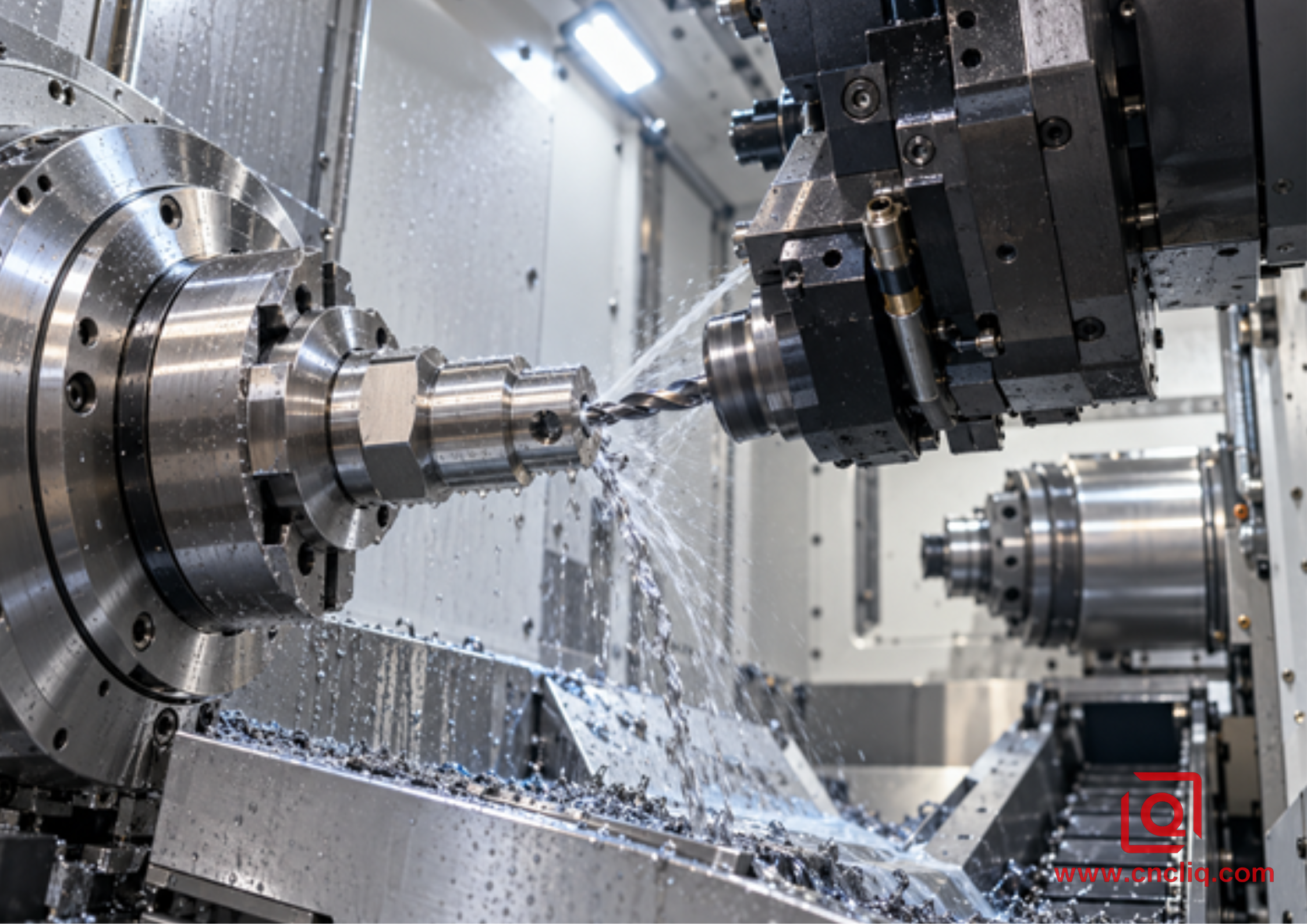
A rotary tool holder is the compact spindle mounted at a powered turret station. Shops also call it a live holder or driven holder. Power arrives through the turret coupling, passes through the holder’s internal drive, and turns the drill, tap, reamer, end mill, or other cutter.
Most of the time, the blank never leaves the main chuck - not yet, anyway. Hold or index that spindle as a C-axis and the turret gains a useful little workshop: face holes, a hole through the diameter, one wrench flat, perhaps a narrow slot. A Y-axis is useful when the cutter must travel off center. An opposed spindle adds back-working access, although the transfer still needs its own alignment and gripping checks.
Picture the holder as the final gearbox and bearing set in a longer chain. I trace the chain from the machine casting to the flute, never the other way around. A dirty face, a tired bearing, or a flexible wall will announce itself somehow - often as heat or chatter, sometimes as a feature that has quietly walked off location. Our article on live tooling on CNC lathes covers the wider machine capability; here the lens stays on the holder and the setup around it.
Orientation is the easy part to understand. Six holes on an end face? An axial head is the obvious first look because its cutter lies roughly along the work spindle axis. A cross-hole or a flat down the outside usually sends us to the radial head, with the cutter turned across that axis. When access gets awkward, an adjustable or multiple-output head may earn its space. Just remember what came with that convenience: more joints, another gear mesh, and more metal swinging near the chuck. Check it on screen; check it again beside the machine.
2. Speed Is a Cutting Requirement, Not a Catalog Trophy
Start with the cut. Note the work material and its condition, the cutter diameter, tool material, coating, flute count, engagement, and coolant arrangement. Then open the cutter maker’s data. A useful starting rpm in metric units is:
RPM = (1,000 * cutting speed in m/min) / (pi * cutter diameter in mm)
Feed rate in mm/min = RPM * effective tooth count * feed per tooth in mm
These are starting calculations, not permission to run the holder flat out. Set a 3 mm drill next to a 16 mm mill on the bench. The small one runs out of rpm first. The large one makes the load meter move. Add an interrupted shoulder, a soft grip, or too much reach and I lower that starting point before the first chip. On a new job, an experienced setter leaves room to listen, watch the load trace, and inspect the first cut.
Now check the ratio stamped or documented for the exact holder. On a 1:1 head, input and output speed remain close. Gear upward for a tiny cutter that cannot reach its range; gear downward when the cut needs more twist than speed. I say “close” deliberately. Gears, seals, and bearings all take their share. Final limits come from the maker’s output curves, not from ideal arithmetic.
Torque and speed meet in a second useful relationship:
Power in kW = (torque in N*m * RPM) / 9,550
This is the page where I stop admiring the catalog and look for the graph. The bold torque figure can live on the left, while the bold rpm figure lives far to the right. Combine them and you have calculated the performance of an imaginary holder. Ask for output at the intended cutting speed, then ask how long that output is allowed: all cycle, intermittent duty, or one short peak.
Before releasing the program, answer five plain questions.
1. What output rpm does this cutter need in this material?
2. What torque or power is available at that rpm, after the selected ratio?
3. How long is the holder expected to stay under load during each cycle?
4. Which approved component has the lowest speed limit: holder, collet, nut, cutter, seal package, or turret drive?
5. Has the programmed rotation direction been checked for this head rather than copied from the last tool?
3. Rigidity Is the Whole Load Path
A holder can be solid and the setup can still be soft. I have seen a heavy radial head blamed for chatter when the real culprit was a cutter pulled out to clear a chuck jaw. I have also seen the opposite: a short tool, good collet, and sensible cut let a fairly compact head run quietly for hours. “Rigidity” belongs to the entire route taken by the cutting force.
Trace that route with a finger. Start at the flute. My finger walks backward from that flute. It pauses at every joint, all the way through the little spindle and turret to the jaw and part. Miss one joint and the diagnosis has a hole in it. Dirt under a mounting face is part of the route. So is a thin wall ringing between jaws. The thickest holder in the cabinet cannot cancel either problem.
Reach is the sneaky item on that walk. For a quick pencil check, I picture the exposed cutter as a diving board. Keep the load and section unchanged and its bend grows roughly with length cubed. Double the reach and the rough model warns of about eight times the deflection. A real assembly has joints and several materials, so that figure is not a shop-floor promise. It is a warning against casual reach.
The turret connection matters, but names can mislead. VDI size, a bolt-on designation, or a familiar “BMT” label does not by itself confirm fit. Before buying, I photograph the turret plate and the coupling. Then I verify its face, bolts, drive, rotation, and output direction against the drawing. Similar catalog names have fooled more than one machine generation.
Published specifications are still valuable when they are read in context. HAIMER, for example, lists 0.003 mm runout at 3 x D and G2.5 balancing at 25,000 rpm for several specific toolholder families. That is a good example of a complete statement because it includes a measuring distance and balancing condition. It is not a blanket live-tool tolerance. Sandvik Coromant’s troubleshooting material reaches the same practical ground from another direction: shorten excess overhang, secure the work and tool, and check holder runout when vibration appears.
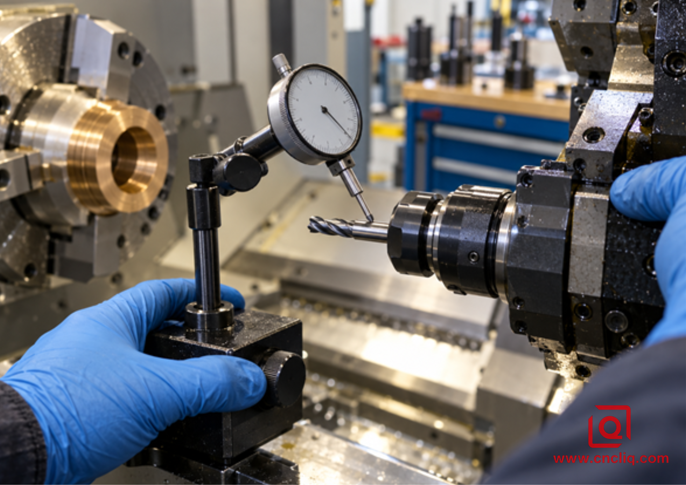
Dial indicator checking live-tool runout at a defined gauge length
4. Choosing the Output Interface
The output connection is where a versatile holder becomes a specific cutting setup. Most setters reach for the ER drawer without ceremony. It covers a lot of tools. I still choose the smallest sensible collet for the shank, because convenience is no excuse for a loose fit. Then tighten the nut to the maker's stated value. A scarred collet squeezed across too much of its collapse range is an expensive way to save a cheap consumable.
A cutter ground with a Weldon flat presents a different choice. Put the screw on that flat and pullout becomes a mechanical problem with a mechanical stop. On a forceful cut I will take that bargain. A tiny finisher changes my mood. Now concentricity gets the attention, and the search moves toward a precision collet, hydraulic grip, or shrink-fit sleeve. An arbor may fit its cutter perfectly and still give the bearings a long lever. I check that lever on paper before the assembly reaches the turret.
An RFQ gains nothing from the fanciest interface name in the catalog. Show the function instead: tolerance, material, nearby walls, and the room available for a holder body. Let the process engineer return a complete holder-and-cutter proposal.
|
Output interface |
Practical strength |
Main caution |
Typical use |
|
ER collet |
Flexible tool range and easy changeover |
Cleanliness, nut torque, collet wear, and runout control |
Drilling, tapping, light to moderate milling |
|
Side-lock |
Positive pullout resistance and solid torque transfer |
Balance and runout may be less favorable for very small tools |
Robust end milling and rougher work |
|
Milling arbor |
Direct support for dedicated cutters |
Higher bending load and larger interference envelope |
Slitting, selected face or side milling |
|
Hydraulic or shrink-fit |
High concentricity and repeatable grip when correctly applied |
Cost, access, service process, and system compatibility |
Finish milling, reaming, small precision tools |
5. Runout, Balance, Bearings, and Heat
Runout is unfair: one flute pays the bill. Imagine four flutes arriving at the work with only one on time. That high edge takes the chip, and the late three polish more than they cut. The temperature creeps up. Wear gathers on one edge. A few parts later, the slot begins reporting the mistake.
Put the indicator where the reading means something, even when another shiny surface is easier to touch. My setup note reads like a short parts list: holder, cutter, adapter, torque, gauge length, indicator point, result. On repeat work I add one more word - cold or warm. Without it, two honest readings can look like a drifting machine simply because they were taken at different moments.
Balance enters the picture as speed and eccentric mass rise. It is not a substitute for a healthy cutter or correct seating. Nor does a balanced body make every attached cutter safe at the holder’s top speed. The lowest approved limit in the assembled stack remains the limit.
Heat is equally specific to the hardware. The warm holder across the aisle is not a thermometer for this one. I follow the maker's warm-up and lubrication guidance, then let the holder establish its own baseline. When sound, hand feel, load, or heat leaves that baseline, the cycle earns a pause. Full speed is a poor diagnostic test for a suspect bearing.
6. Coolant and Chips Can Decide the Result
A neat calculation can still fail under a bird’s nest of chips. A turn-mill enclosure hosts an untidy party: stringy turning swarf, little milling chips, and perhaps two holes meeting out of sight. I watch the exit, not merely the nozzle.
Through-tool coolant is helpful when a deep hole hides the cutting edge. It is only useful if the whole route is approved for the pressure: machine supply, turret union, holder seals, collet arrangement, and cutter. An external nozzle is perfectly serviceable for many open cuts, but check the stream at the beginning and end of motion. A jet that lands on the holder body looks busy and cools very little where it counts.
Breakthrough needs a plan of its own. Chips can pack at intersecting holes, and a hanging burr can survive until assembly. In aluminum, recutting encourages built-up edge and scratches. In stainless steel, repeated rubbing at the bottom of an overcautious peck can harden the surface. “Add more pecks” is therefore not a universal cure. Drill geometry, coolant delivery, depth, and chip shape should decide the cycle.
The existing guide to chip control in high-speed aluminum CNC turning is useful when the problem begins with material, edge geometry, or coolant. Where a pocket loads a long tool from the side, our trochoidal-milling guide explains how controlled radial engagement can reduce the demand. Neither strategy repairs a loose or overextended holder; stability still comes first.
At prove-out, pause after the first representative feature. Before pressing cycle start again, hold the first chip and part under a lamp. The exit, edge, flute, and finish usually have something to say. That short inspection catches more than another minute spent admiring a simulation.
7. A Shop-Floor Selection Matrix
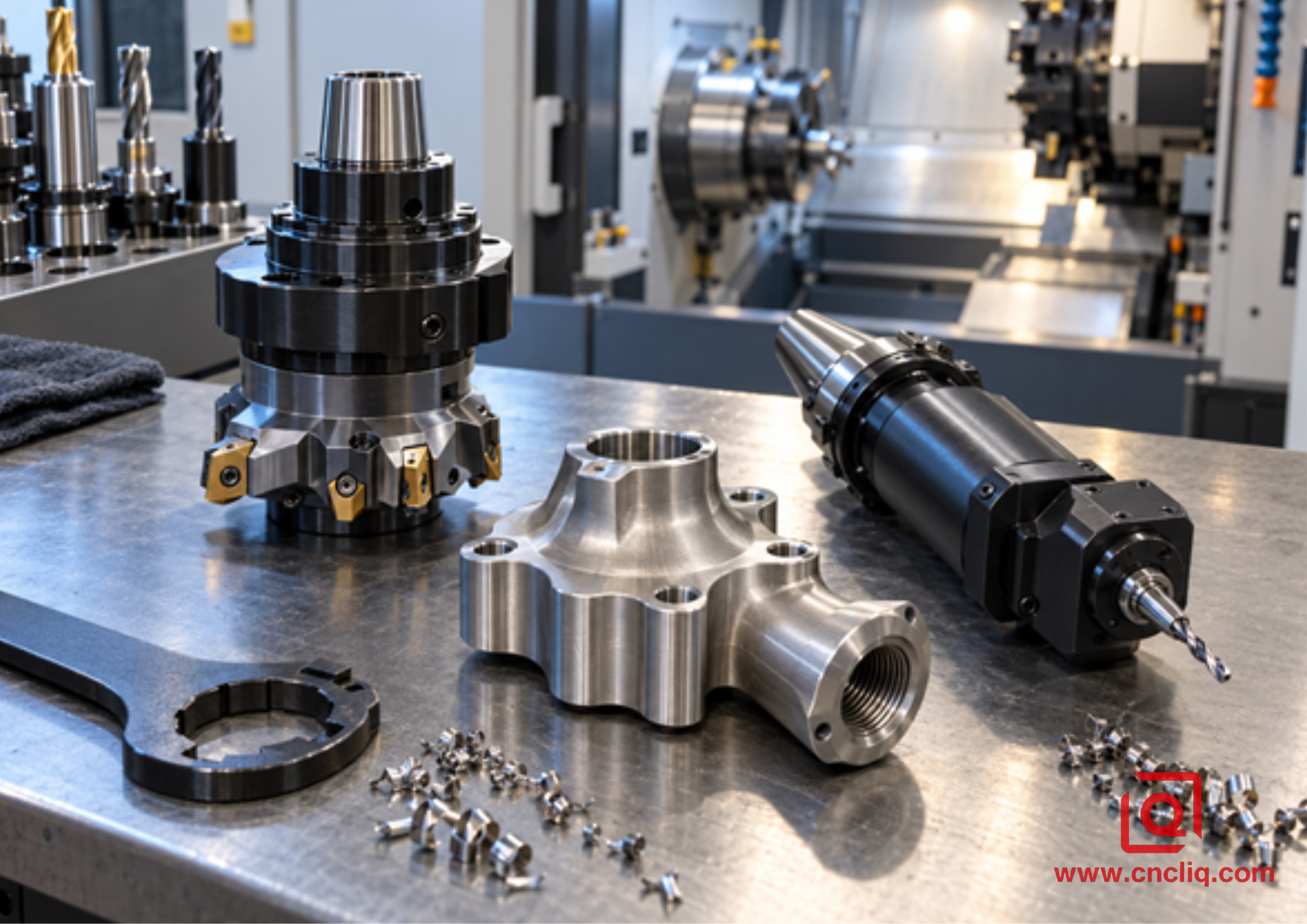
Short rigid and longer high-speed rotary tool-holder arrangements on a setup bench
|
Operation |
What usually matters first |
Holder direction |
Sensible first check |
|
Small face drilling |
Output rpm, runout, chip evacuation |
Axial |
Calculate rpm from drill diameter; verify through-coolant path |
|
Cross-hole drilling |
Alignment, entry condition, burr at breakthrough |
Radial |
Indicate holder square; plan spot or controlled entry if needed |
|
Wide OD flat |
Torque, rigidity, overhang, C-axis clamp |
Radial |
Reduce projection and radial engagement before raising power demand |
|
Face bolt circle |
Angular location, runout, tool length |
Axial |
Verify C-axis zero and feature-to-datum inspection method |
|
Off-center slot |
Y-axis travel, body clearance, cutter deflection |
Axial or radial by geometry |
Simulate full holder envelope, not only the cutter |
|
Rigid tapping |
Synchronization, torque, reversal duty, coolant |
Axial or radial |
Confirm machine cycle and holder suitability for reversal |
|
Finish reaming |
Runout, alignment, stable allowance |
Usually axial |
Measure runout at working gauge length and control pre-hole size |
That table does not crown a champion. The broad flat may settle down with a compact 1:1 head. The tiny drill may not wake up until a speed increaser arrives. Let the cut make the shortlist. Let the actual machine, jaws included, make the final choice.
8. When the Cut Starts Talking Back
Chatter invites knob turning. Resist it. I first write down the rpm, feed, engagement, projection, tool, holder, and spindle angle where the mark appears. A phone photo of the setup helps too. Then one item changes. If five settings move together and the noise disappears, we have a good part but no useful diagnosis.
1. Read the holder model, ratio, rotation arrow, and offset at the machine. Do not trust yesterday’s setup sheet without looking.
2. Wipe the turret face, locating features, collet taper, nut, coupling, and cutter shank. A chip here is not a small chip once the cut begins.
3. Indicate the cold tool at its working gauge length. If the needle looks wrong, I reseat once and keep both numbers. The discarded reading may be the useful clue.
4. Slide the cutter inward until only honest clearance remains. Then walk it past the jaws, both spindles, nearby stations, and the approach move.
5. Lighten radial engagement or depth before blaming motor power. This separates a load problem from a resonant one.
6. Move speed in modest steps and protect a real chip load. Slowing a cutter until it rubs only trades chatter for heat.
7. Stop after the first representative feature. Look at flute wear, chip shape, coolant aim, breakthrough burr, and the actual surface.
If the complaint follows one holder from tool to tool, the holder or turret drive deserves attention. When every sketch shows a stretched tool and a big cutter, I stop sketching. That feature is asking for a B-axis spindle or a mill. Our CNC turning and turn-mill machining for concentric housings comparison is useful here; the broader turn-mill DFM guide covers setup and collision tradeoffs.
9. Anonymous Case: 17-4PH Robotic Gripper Pivot
A European automation buyer sent a compact 17-4PH pivot with two bearing lands, a hexagonal collar, a radial oil hole, one off-center face hole, and a wrench flat. The example reflects Liqin's published turning, milling, mill-turn, deburring, and inspection scope. It does not promise that every similar drawing will use this route.
Plan A would have made parts. Turn the lands, release the chuck, and let a machining center finish the odd features. The weak point was relocation. Both the hole and flat were clocked from the finished bearing axis, so a second fixture added a relationship that inspection would have to recover. The process team tried a main-spindle and live-tool route instead. Its logic is close to Liqin’s custom fork support shoulder bolt, another part family combining turned diameters with a milled drive feature.
The face drill cut cleanly. The radial drill did not. It left a light witness at entry and an untidy burr where the holes met. The indicator and setup check told a better story: the drill had been pulled out to miss a jaw corner, and most coolant was washing the holder body.
The fix would never make a dramatic sales video. That was precisely why the team trusted it. They tucked the drill inward, crept through the complete C-axis sweep, and bent the coolant stream back onto the point. A brief locating move gave the radial drill a calm place to enter. Inspection went back to the functional axis. Hole location and flat angle referenced the turned datum, while the hidden intersection received its own lighting and magnification rule.
This case did not prove that live tooling always beats two machines. It proved that reach, entry, coolant, deburring, and measurement have to agree. Liqin’s precision motor flange and front end cap shows the same datum-first thinking around a bearing bore, pilot, and face.
10. Build an RFQ the Shop Can Use
A drawing carries dimensions. The RFQ should also tell the shop which failure will ruin Monday morning on the assembly line. Two files go out together. The 2D drawing governs, and the neutral model makes the shape hard to misunderstand. A short cover note fills the gaps: material condition, order pattern, finish, heat treatment, clean edges, paperwork, packing, and the launch date.
Now mark three features that would stop assembly. Maybe the cross-hole lives or dies by the bearing axis. Maybe the face pattern must clock to one flat. Maybe a spiral mark turns a seal face into scrap. Say which. If a particular inspection method governs acceptance, put its name beside the requirement. Tight access deserves the mating envelope too. Do not make the setter invent the missing half of your assembly.
In return, I want to see how the shop thinks: machine, chucking order, holder direction, odd tools, inspection, assumptions, and what was left out. For a real review, send the files through the contact page. Liqin can compare a live-tool route, a fuller turn-mill plan, and a controlled split process before quoting.
FAQ
1. Should I buy the holder with the biggest rpm number?
No. Sometimes the small drill needs every revolution. Swap in the wide mill and the red line moves. Torque or stiffness usually puts up the first barrier. After the cutter calculation, my pencil moves to the margins: power curve, reach, runout, coolant, bearings, turret. So I do not award the job to the fastest box. It is the head that remains quiet where this cut has to run.
2. How much live-tool runout is acceptable?
There is no honest universal number. The same few micrometers barely annoy a stout rougher and ruin the morning for a tiny drill. A naked runout number is nearly useless. Give it a gauge length and an indicator point. Only then do I compare it with the tool, print, finish, and the parts the process has already proved it can make.
3. Face or side: which holder orientation fits?
Let the feature answer first. A face pattern points me toward an axial head. A hole across the diameter or a flat down the outside points me toward a radial one. Before ordering, I still sweep the full body through C and Y motion, rotation sense, turret fit, jaws, and neighboring stations.
4. Can a live-tool lathe replace a machining center?
On the right part, yes. On the wrong part, not for long. Finding that boundary beats repeating a slogan. Give the lathe a mostly round body with a handful of holes, threads, slots, and flats. It feels at home. Now add a broad pocket, long reach, large cutter, or heavy 3D removal. I turn toward the machining center or B-axis spindle. Compare datum risk and total process cost.
5. What helps Liqin quote quickly?
Start with the two files, then add the things files do not say well: material condition, order pattern, critical datums, finish, edge rules, paperwork, timing, and mating limits. Mark the three failure-sensitive features. That lets the engineering team review holder access, clamping, deburring, and measurement before pricing the job.
Summary
Choose a rotary holder from the cut backward. Begin at the flute and walk backward. Find its speed, see what torque remains there, shorten the lever, put a location beside the runout number, and watch where coolant and chips really travel. If the reach or load makes that little spindle unhappy, move the feature to heavier iron. A clear RFQ moves that choice to the desk, while the plan is still cheap to change.
Contact Information
Company: Ningbo Liqin Industry Co., Ltd.
Daily customer maintenance & after-sales support:service@shturl. zhuwanying@cncliq.com
New inquiry, quotation & order discussion:business@shturl. zhouli@chinaliqin.com
Hotline: +86 18757148656
Disclaimer
All technical articles, material specifications, machining recommendations, and surface treatment details published on this blog are for informational and reference purposes only. Please note that general blog insights do not replace signed technical agreements. Because custom parts vary by material heat numbers, machine calibrations, and specific tolerances, binding quality specs are governed solely by your approved CAD drawings, signed contracts, and formal quality plans.
All customer case studies featured on this blog have been thoroughly anonymized and sanitized. The performance metrics, manufacturing workflows, and imagery displayed serve solely to demonstrate our custom machining capabilities and do not represent a single universal standard for all orders.
Liqin Manufacturing Team
Built on 18 years of precision engineering experience, Ningbo Liqin Industry manufactures high-tolerance metal components for demanding global markets. We operate out of a 6,500 m² production hub equipped with over 150 machines, running 4-axis and 5-axis CNC machining, mill-turn machining, cold extrusion, and pressure die casting under one roof. This setup allows us to manage projects seamlessly, taking parts from initial CAD concepts directly to finalized shipments.
We handle quality control with zero compromise. We treat tight tolerances with the engineering discipline they require. Backed by ISO 9001, ISO 13485, and IATF 16949 certifications, our QA engineers run strict IPQC, FQC, and OQC checks on every single production batch. From CMM dimensional mapping and optical profiling to hardness and salt-spray testing, we validate your critical specs upfront—so you receive drop-in ready components with zero assembly headaches or costly line stoppages. On top of manufacturing, you can rely on us for two-hour response times on new RFQs, direct support for prototype sampling, and smooth export shipping across Europe, North America, Asia, and Oceania.
Welcome your inquiries and samples. Visit our website or contact us directly for a competitive quote!
