 English




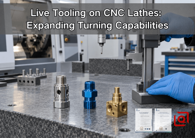
Are you still moving a turned part to a machining center just to add 2 cross-holes, a wrench flat, or an off-axis thread? That extra operation may look harmless on a routing sheet. In the shop, that small 2nd operation shows up as a fixture to build, a datum to find again, a queue to wait through, and 1 more chance for a hidden burr or seating error. The pages below walk through the decision the way a process engineer would: what the machine can really do, what tends to go wrong, and when the milling work should stay on a separate machine.
So the 1st question on an RFQ should not be whether a shop owns a live-tool lathe. Ask which machine, holder, cutting sequence, and measurement plan will hold the related features on your print. That is the point where a machine option turns into a useful production route. Done well, the route is shorter, ownership is clearer, and the part reaches your line ready to fit.
What Live Tooling Means on the Shop Floor
Watch a normal turning cut: the chuck carries the rotation and the insert stays put. That arrangement handles OD steps, faces, grooves, tapers, and coaxial bores very well. Live tooling, also called driven tooling, adds powered rotary cutters to the turret. Now the same chucking can receive a drilled port, a tapped face hole, a slot, or a milled flat.
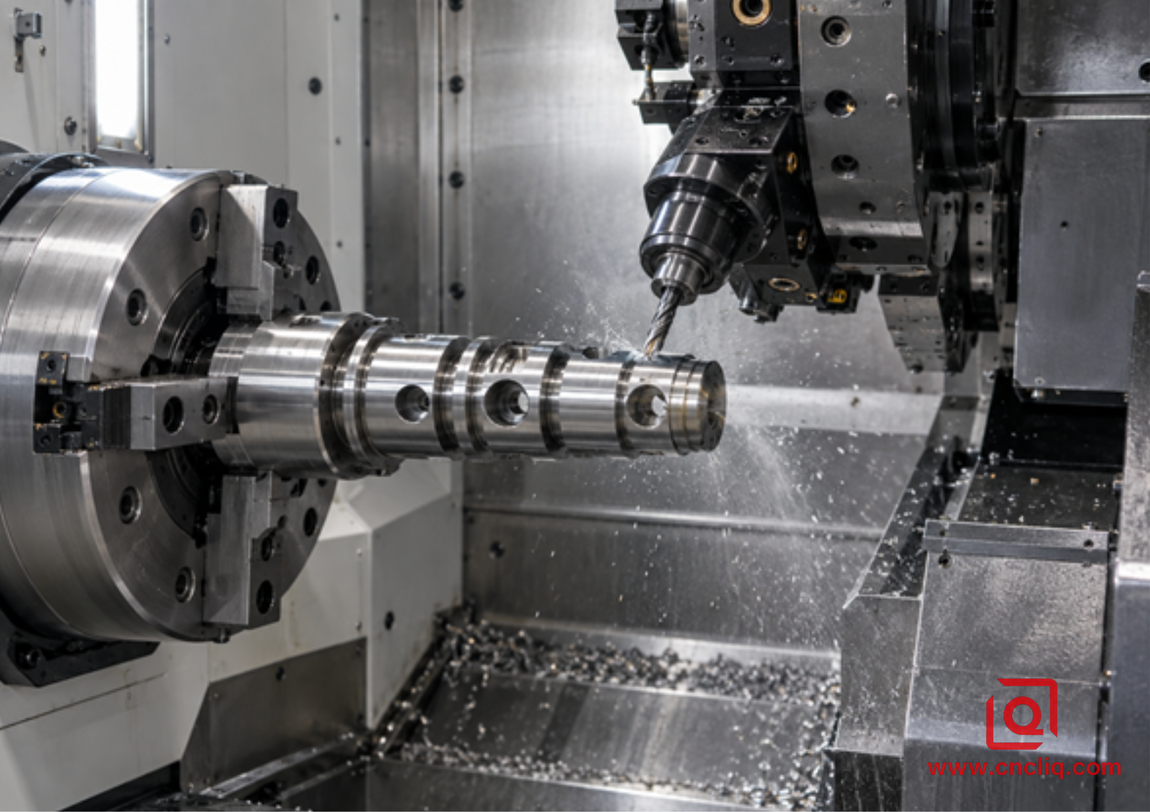
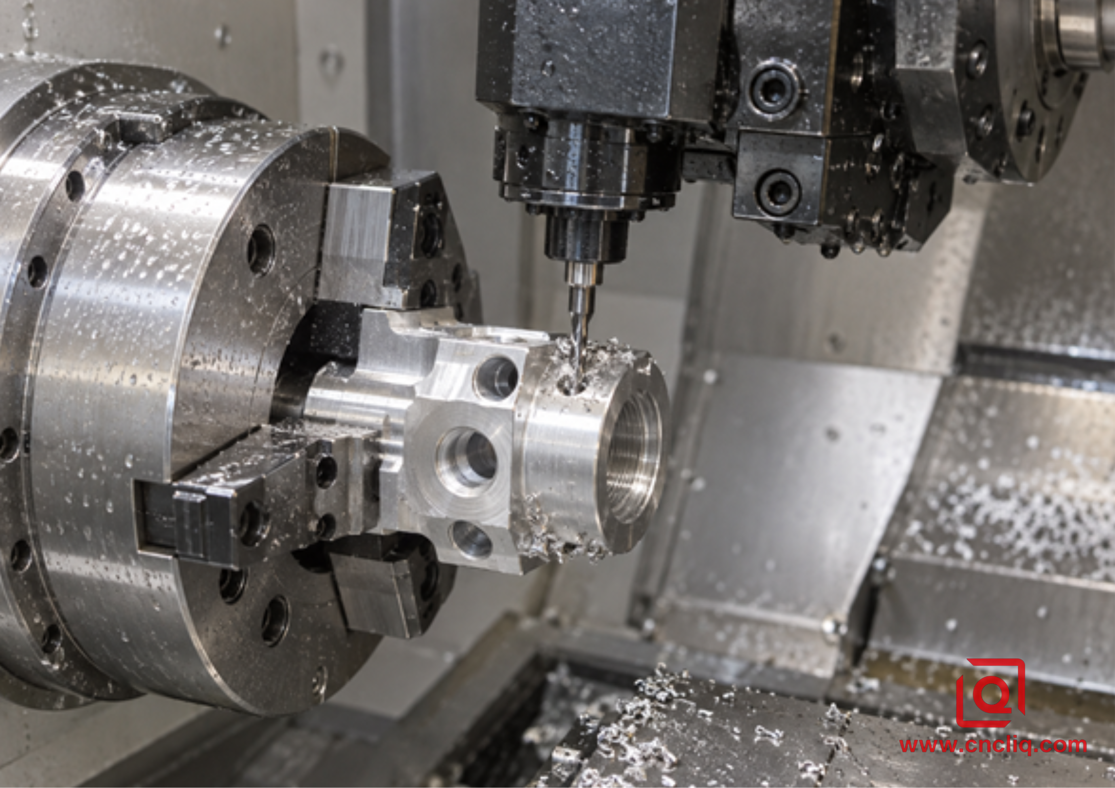
A quick mental picture helps. A radial live tool approaches the outside diameter to drill a cross-hole. An axial live tool points toward the chuck and mills a feature on the front face. The main spindle's C-axis indexes the part to a commanded angle or moves continuously with a linear axis. If the machine also has a Y-axis, the cutter can reach above or below the spindle centerline instead of relying only on X-C interpolation.
Do not confuse live tooling with a live center. A live center is a bearing-supported point in the tailstock that rotates with and supports a long workpiece; it does not cut. A live tool is a powered cutting station. The Haas Lathe Operators Manual describes axial and radial live tools for milling, drilling, and slotting, with shapes produced through C-axis and/or Y-axis motion.
The Capability Stack: Live Tool, C-Axis, Y-Axis, and Sub-Spindle
Live tooling is often used as shorthand for several machine functions. They should be checked separately because each one solves a different geometry problem.
|
Machine capability |
What it controls |
Typical features it enables |
What a buyer should verify |
|
Powered axial tool |
Cutter rotates parallel to the main spindle axis |
Face holes, bolt circles, face slots, front-face tapping |
Available speed, torque, collet size, axial clearance |
|
Powered radial tool |
Cutter rotates perpendicular to the main spindle axis |
Cross-holes, radial threads, keyways, outside flats |
Holder projection, interference, coolant delivery |
|
C-axis |
Main spindle indexes or interpolates as a rotary axis |
Clocked holes, equally spaced features, polar milling |
Positioning method, brake or clamp use, programmed resolution |
|
Y-axis |
Turret moves off the spindle centerline |
Offset holes, true flat milling, off-center pockets |
Travel, clearance, axis accuracy under cutting load |
|
Sub-spindle |
Opposed spindle receives the part |
Back-face work without manual reclamping |
Transfer grip, cutoff allowance, datum-transfer inspection |
A C-axis does not automatically make a machine suitable for every milled feature. With X-C polar interpolation, the control converts linear commands into coordinated X movement and spindle rotation. That works well for many face profiles and centered features. A true Y-axis is normally the cleaner choice for off-center slots and pockets because the cutter follows a direct linear path. Likewise, a sub-spindle helps finish the back end, but only if there is enough grip length and the transfer does not distort a thin wall.
The wider process family is explained in our guide to 3-axis and 5-axis CNC machining. For cylindrical parts with significant off-axis work, also compare the datum strategy in CNC turning versus turn-mill for concentric aluminum housings.
Radial live-tool drilling of an aluminum fitting
What Parts Gain the Most From Live-Tool Turning?
The best candidates begin as round bar, tube, a forging, or a near-round blank, yet carry several non-rotational features. A hydraulic fitting with intersecting ports is a good example. So is a sensor housing with a connector flat. The same logic fits keyway shafts, clocked medical connectors, ported valve spools, and pneumatic couplings with wrench flats.
I start with the print, not with the name in the title block. Live tooling deserves serious consideration when 1 or more of the following conditions appear:
· A milled feature has a tight positional relationship to a turned diameter or bore.
· Several radial holes must be clocked around the circumference.
· A short part is difficult to locate repeatably in secondary soft jaws.
· Batch size makes repeated loading and work-in-process handling expensive.
· Cosmetic surfaces or sealing lands could be damaged during transfer.
· A completed back face is possible through an opposed spindle.
· Lead time is being consumed by queues between turning and milling departments.
The custom precision gearbox output shaft on our product site illustrates the kind of part family where turned steps, grooves, and milled transmission features must be planned as 1 dimensional chain. A different example is a custom hydraulic manifold, where ports, threads, sealing faces, and internal passages make datum control and deburring as important as the cutting cycle itself.
Why 1 Clamping Can Improve the Result
The strongest benefit is not a dramatic spindle-speed claim. It is continuity of location. In a split route, the lathe establishes the primary axis, then an operator removes the workpiece, cleans it, seats it in another fixture, and picks up the datum again. Each step has variation: jaw seating, chip contamination, fixture repeatability, probing strategy, clamping force, and operator method.
A 1-clamping route keeps turned and live-milled features inside the same machine coordinate system. That does not guarantee a perfect part; tool runout, thermal growth, servo following error, cutting force, and inspection uncertainty still exist. It does remove an entire family of transfer errors. The Okuma Multitasking Machining Guide identifies setup reduction, improved accuracy, lower human error, and reduced tolerance stack-up as central multitasking benefits.
The Shop-Floor Limits That Decide Whether It Works
Live-tool turning is compact and efficient, but the driven station is not a full-size machining-center spindle. A sound plan respects the following limits.
Start With Torque, Not the RPM Headline
Small drills and end mills need speed; large cutters and tough alloys need torque. Maximum rpm alone is not enough. Ask for the available torque or power curve near the planned cutting speed, along with the largest practical cutter in the selected material. As a machine-specific reference, not a universal value, the 2021 Haas manual lists a 6,000 rpm maximum for the live-tool drive covered in that document and describes it as intended for medium-duty milling. This is why every quotation should be tied to the actual machine model rather than a generic live tooling label.
Holder Runout and Projection
Driven-tool bearings, collets, adapters, and cutter shanks form a tolerance chain. A short, clean, correctly torqued holder is usually more stable than a long assembly built to reach past the chuck. Excessive projection magnifies deflection and chatter. Before production, the machinist should indicate the holder at a defined gauge length, verify tool seating, and record the result when the feature is critical.
Turret Alignment and Cutting Direction
An axial holder must be aligned with the spindle axis; a radial holder must be square to it. A small angular error can create tapered holes, mismatched slot walls, or uneven tool wear. Alignment also affects whether a drill enters a curved surface cleanly. A spot, pilot, or controlled entry move may be required on a cylindrical OD.
Thermal Control and Chip Evacuation
Turning and milling load the machine differently. Intermittent live-tool cuts can warm a compact holder while long stringy turning chips remain near the feature. Coolant must reach the cutting edge and carry chips away from drilled intersections. For aluminum, chip welding and built-up edge often become the practical limit; for stainless steel, heat and work hardening require firm engagement and a stable toolpath. Our OEM aluminum CNC turning alloy guide explains why grade, temper, chip formation, and tool geometry must be treated as 1 decision.
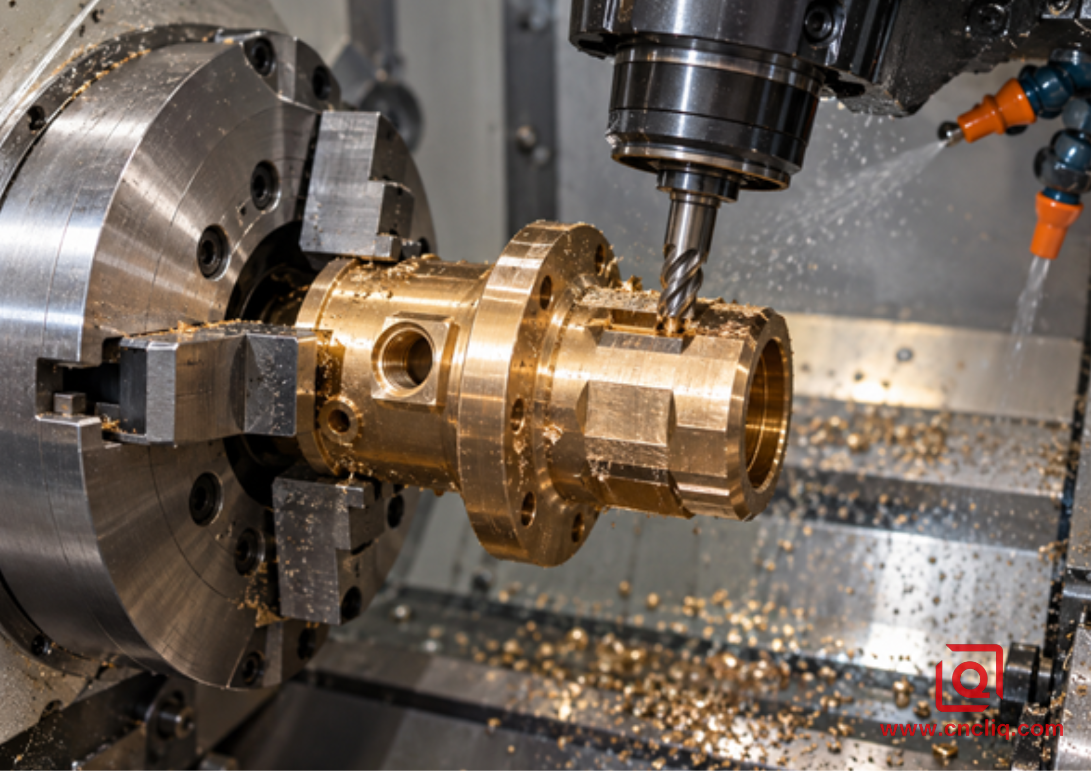
Y-axis live milling on a bronze sensor housing
A Practical Process Plan From Drawing to Finished Part
1. Define the Functional Datum Chain
Mark the features that must stay related after assembly. If a radial hole feeds an internal bore, the drawing should state its position from a functional datum instead of relying on a vague note. If the component seals, identify the sealing diameter, face, groove, and allowable burr condition. The process route should preserve those relationships, not merely follow the easiest feature order.
2. Match the Machine Configuration to the Geometry
List the needed operations and map each one to an axis and holder orientation. Centered face drilling may need only an axial live tool. A cross-hole normally needs a radial station and C-axis indexing. An offset pocket may need Y-axis travel. A finished rear thread may justify a sub-spindle. This simple mapping prevents suppliers from quoting a machine that can theoretically hold the part but cannot reach the features efficiently.
3. Plan Workholding Before Toolpaths
Decide the chucking length, jaw contact, stop face, and cutoff allowance. Thin walls may change size under hydraulic jaw pressure. Short parts can lack enough grip for both heavy turning and later transfer. When a sub-spindle is used, define which finished surface it may clamp and how cosmetic damage will be prevented.
4. Sequence Roughing, Live Work, and Finishing
There is no universal sequence. Heavy rough turning first can release material stress and create chip space. Finishing a critical bore too early may allow later milling forces or heat to shift it. A common logic is rough-turn, live-machine noncritical features, stabilize with coolant or a short dwell if needed, then finish the critical diameter and seal face. The final sequence should follow the parts stiffness and tolerance chain.
5. Control Burrs at Intersections
Cross-holes that break into a bore are a classic trouble point. The burr may be hidden from normal viewing yet cut an O-ring or restrict flow. Toolpath direction, drill point geometry, a controlled breakthrough feed, back-chamfering, brushing, or a defined secondary deburr may be needed. Inspection must confirm the intersection itself, not only the hole diameter.
6. Simulate and Prove Out Safely
Live-tool assemblies occupy more space than static turning tools. The CAM model should include the chuck, jaws, turret, holder body, cutter, sub-spindle, and the remaining stock. Prove-out should use conservative overrides and safe clearances. Collision avoidance supports the process, but it does not replace a complete digital setup or operator review.
7. Measure in the Same Logic Used to Manufacture
Use the functional datums from the drawing when creating the CMM or optical-inspection program. A first-article report should show the characteristics that justified 1-clamping production: bore-to-port position, flat-to-axis orientation, runout, and any transfer-related rear features. For recurring batches, agree on inspection frequency and reaction limits before production begins.
Live Tooling vs. Separate Lathe and Mill
|
Decision factor |
Live-tool lathe or turn-mill |
Separate CNC lathe and machining center |
|
Best geometry |
Mostly rotational part with several cross or face features |
Part dominated by large pockets, broad planar work, or heavy 3D milling |
|
Datum continuity |
Strong when critical turning and milling remain in 1 clamping |
Depends on the secondary fixture and datum pickup |
|
Workholding |
Often 1 primary workholding system, plus optional sub-spindle transfer |
Usually a turning setup plus secondary jaws or a dedicated milling fixture |
|
Cutting capacity |
Excellent for drilling, tapping, slots, flats, and light-to-moderate milling |
Generally stronger for deep, wide, high-metal-removal milling |
|
Programming |
More axis coordination and collision management |
Simpler programs, but more routing and setup management |
|
Batch flow |
Less work-in-process and fewer queues |
Flexible when machines and operators are already available |
|
Cost driver |
Machine time, live holders, CAM, and prove-out |
Extra fixture, handling, setup, inspection, and queue time |
Do not compare only hourly machine rates. Build the quote from total process cost: programming, raw material, setup, cycle time, special holders, soft jaws, deburring, inspection, outside finishing, packaging, and expected batch quantity. Our guide to comparing CNC factory quotations provides a structured way to normalize those items.
Anonymized Customer Case: Stainless Fluid-Control Sleeve
An anonymized industrial-equipment customer requested a small stainless steel fluid-control sleeve made from bar stock. The part combined a finished outer diameter, a precision internal bore, 4 radial flow holes, 2 wrench flats, a face thread, and an internal cross-hole intersection that had to be free of loose burrs. The production volume was suitable for repeat batches, but the drawings main risk was geometric: the radial pattern and flats were functionally related to the finished bore.
The initial process concept used CNC turning followed by a separate milling fixture. It was manufacturable, but it introduced a 2nd datum pickup and a custom nest around a short finished diameter. The revised plan kept the bore, OD, radial holes, flats, and face thread on a C-axis and Y-axis live-tool turning center. The front features were completed in the main spindle; the rear face was finished after controlled transfer to the opposed spindle. The exact cutting parameters remained part-specific and were established during prove-out rather than copied from a generic table.
The control plan focused on risk, not inspection theater. The 1st article received CMM verification of hole position from the bore axis, optical checks on flat width and angular orientation, thread gauging, and magnified inspection of each hole intersection. In-process checks monitored the bore and OD, while the final plan included cleaning and a documented visual standard for burrs. By preserving the main datum chain in 1 machine, the team removed the special milling fixture and reduced handling stages. This case is illustrative and anonymized; final results for any new part depend on its drawing, material condition, quantity, and approved quality plan.
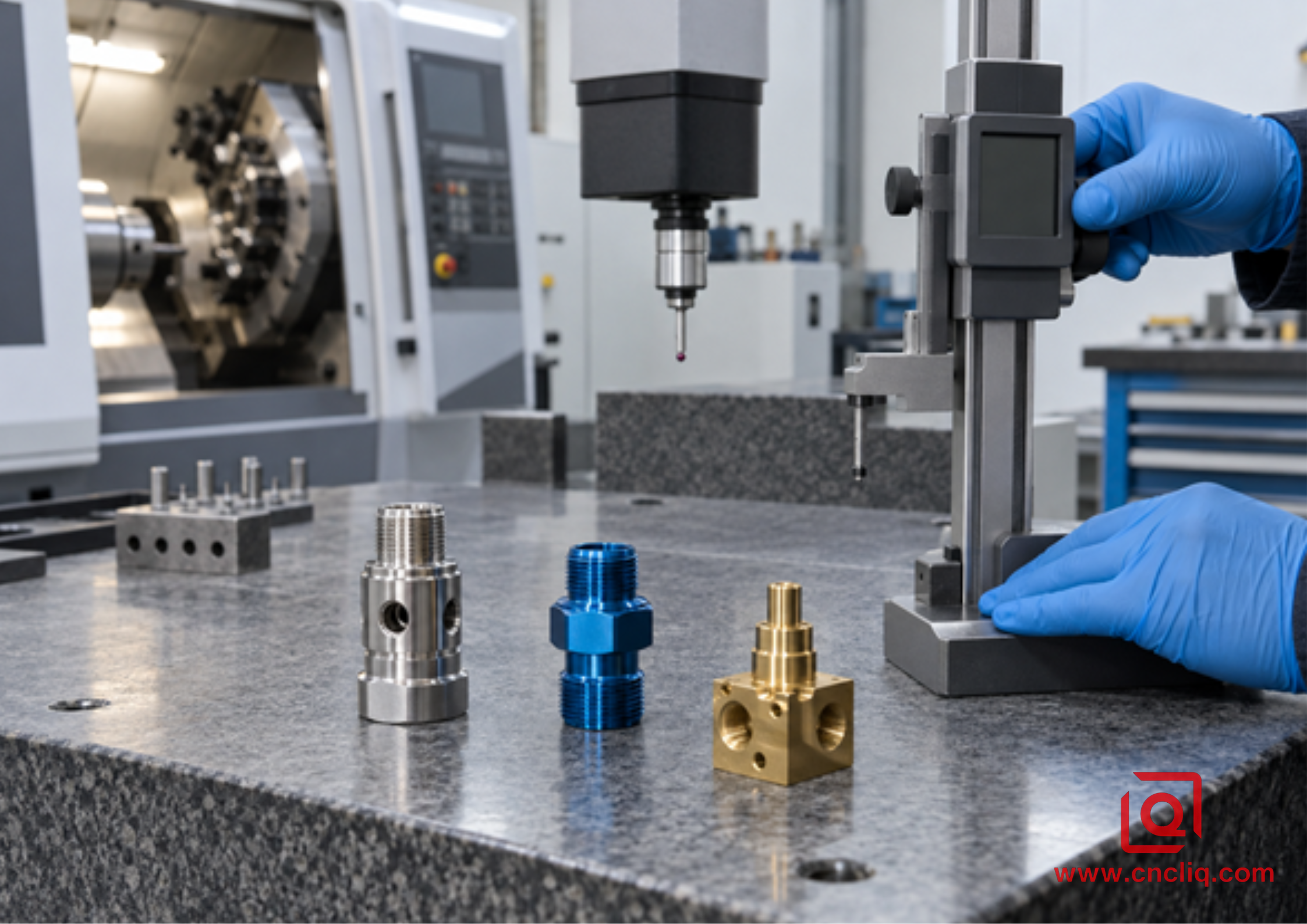
Inspection of completed mill-turn components
DFM Choices That Make Live Tooling Easier to Quote
Good drawings give the supplier room to choose an efficient path without weakening function.
· Dimension clocked features from a clear datum and use GD&T where the relationship matters.
· Avoid deep narrow slots that force a long, flexible end mill unless the geometry is functional.
· Provide realistic corner radii so a robust cutter can be used.
· State whether a cross-hole intersection must be burr-free, radiused, or flow-tested.
· Keep tool access around flats and radial ports clear of unnecessarily tall shoulders.
· Specify threads completely, including standard, class, depth, and any gauge requirement.
· Mark cosmetic zones separately, then write down which handling marks are acceptable there.
· Send the STEP model for toolpath planning and the controlled 2D print for tolerances, notes, and acceptance.
If the grade is open, tell us the job first. Does the part need strength, low weight, corrosion resistance, conductivity, sterilization, or a particular finish? Aluminum or stainless steel is not enough. For aluminum parts, the comparison in choosing the right CNC process for custom aluminum parts helps connect geometry to the appropriate machine route.
What to Send for a Useful Live-Tooling Quote
A fast quotation is useful only when it prices the same technical scope you intend to buy. Send the following items together:
1. Native or neutral 3D model, preferably STEP, plus a dimensioned PDF drawing with revision.
2. Exact material grade, temper or condition, and any material-certificate requirement.
3. Prototype quantity, 1st production quantity, and expected annual volume.
4. Critical-to-function dimensions and the datum scheme.
5. Required finish and any heat treatment, plating, passivation, anodizing, or masking.
6. Which inspection records you need: 1st-article report, CMM data, capability study, or gauge record.
7. Your rules for cleanliness, burrs, sharp edges, leak testing, and packaging.
8. Target delivery date and shipping destination.
Ask the supplier to return a process summary with the quotation: proposed machine type, number of clampings, major special tooling, outside processes, inspection approach, exclusions, and any drawing questions. That response reveals more than a low unit price. It shows whether the supplier has understood why live tooling is being considered.
For a drawing with cross-holes, flats, off-axis threads, or a tight relationship between turned and milled features, send the CAD files through our contact page. Mark the 3 characteristics that would stop your assembly if they drift. Our engineering team can review the datum chain and quote a live-tool, turn-mill, or split-process route based on the actual geometry.
FAQ
1. Where does live tooling end and mill-turn begin?
Live tooling names the powered cutter in the turret. Mill-turn is the wider process: turning and milling planned together on the same machine. A basic machine might stop at X, Z, and C. Move up the range and you may find Y motion, an opposed spindle, a lower turret, or a swiveling B-axis milling spindle. Read the machine configuration; the sales label is not enough.
2. Does every live-tool lathe need a Y-axis?
No. C-axis indexing with axial or radial live tools can handle bolt circles, cross-holes, radial tapping, and some centered slots. A Y-axis becomes important when the cutter must move away from the spindle centerline, when true linear milling is preferred, or when the feature cannot be produced efficiently through X-C interpolation.
3. Can live tooling hold the same tolerances as a machining center?
It can hold demanding relationships on suitable parts, especially when a turned datum and a milled feature stay in 1 clamping, but tolerance capability is never guaranteed by machine type alone. Holder runout, tool projection, cutting load, thermal state, workholding, material, machine condition, and measurement method all affect the result. Request a part-specific process and inspection plan.
4. When is a separate milling operation still better?
Picture a deep, broad pocket or a surface that needs sustained heavy removal. That work belongs on a machining center more often than on a turret-driven tool; the same goes for extensive 3D cutting and largely prismatic parts. For a handful of parts, an existing simple mill fixture may also cost less. The right answer comes from total process cost and risk, not setup count alone.
5. What information helps a supplier quote live-tool parts accurately?
Send the model and controlled drawing together. Add the material condition and quantities, then flag critical datums, finish, burr and cleanliness rules, inspection paperwork, and the delivery date. Circle the cross-feature relationships that can stop assembly. In return, ask the supplier to name the machine, clamping count, special tooling, inspection method, and exclusions. Clear inputs reduce both quotation padding and later change charges.
Summary
Keep the mental model simple. Start with a mainly round part; powered tools let the lathe add its cross-holes, flats, slots, and off-axis threads before that part leaves the chuck. The win is not an impressive axis count. It is the datum you do not have to find again, the fixture you do not build, and the queue the part never enters. Check the print against the real C-axis, Y-axis, holder, spindle, and sub-spindle. Then look at runout, heat, chip flow, burr access, and inspection. Only after that should 1-clamping and split processing be priced against each other.
Contact Information
Company: Ningbo Liqin Industry Co., Ltd.
Daily customer maintenance & after-sales support:service@shturl. zhuwanying@cncliq.com
New inquiry, quotation & order discussion:business@shturl. zhouli@chinaliqin.com
Hotline: +86 18757148656
Disclaimer
All technical articles, material specifications, machining recommendations, and surface treatment details published on this blog are for informational and reference purposes only. Please note that general blog insights do not replace signed technical agreements. Because custom parts vary by material heat numbers, machine calibrations, and specific tolerances, binding quality specs are governed solely by your approved CAD drawings, signed contracts, and formal quality plans.
All customer case studies featured on this blog have been thoroughly anonymized and sanitized. The performance metrics, manufacturing workflows, and imagery displayed serve solely to demonstrate our custom machining capabilities and do not represent a single universal standard for all orders.
Liqin Manufacturing Team
Built on 18 years of precision engineering experience, Ningbo Liqin Industry manufactures high-tolerance metal components for demanding global markets. We operate out of a 6,500 m² production hub equipped with over 150 machines, running 4-axis and 5-axis CNC machining, mill-turn machining, cold extrusion, and pressure die casting under 1 roof. This setup allows us to manage projects seamlessly, taking parts from initial CAD concepts directly to finalized shipments.
We handle quality control with zero compromise. We treat tight tolerances with the engineering discipline they require. Backed by ISO 9001, ISO 13485, and IATF 16949 certifications, our QA engineers run strict IPQC, FQC, and OQC checks on every single production batch. From CMM dimensional mapping and optical profiling to hardness and salt-spray testing, we validate your critical specs upfrontso you receive drop-in ready components with zero assembly headaches or costly line stoppages. On top of manufacturing, you can rely on us for 2-hour response times on new RFQs, direct support for prototype sampling, and smooth export shipping across Europe, North America, Asia, and Oceania.
Welcome your inquiries and samples. Visit our website or contact us directly for a competitive quote!
