 English





Are you still deciding whether a concentric aluminum housing belongs on a conventional CNC turning center or a turn-mill multi-tasking machine? The choice looks simple until one bore must run true to an external pilot, a face groove must seal, and several radial ports must land at exact angles. At that point, the real question is not which machine sounds more advanced. It is which process keeps the functional axis intact from raw stock to final inspection.
This guide explains that decision from the shop floor. We compare process chains, datum control, distortion risk, inspection effort, cost drivers, and the drawing information that helps a supplier quote correctly. The focus is cylindrical aluminum housings used around bearings, optics, sensors, valves, compact motors, and other assemblies where runout and fit matter more than appearance alone.
Short answer: choose CNC turning when most critical surfaces are rotational, the milled features are simple or loose, and a controlled second setup will not break the datum relationship. Choose turn-mill multi-tasking when the bore, pilot, sealing face, radial ports, flats, slots, or backside features form one functional tolerance chain and should remain tied to a common axis.
1. Start With the Functional Axis, Not the Machine List
A housing can look round without being functionally concentric. A bearing seat, optical bore, locating spigot, seal land, threaded nose, and end face may each pass their size checks while the assembly still vibrates or leaks. Size answers “how large?” Geometric controls answer “where is the surface relative to the datum axis?” An RFQ should identify the feature that establishes rotation or alignment, then state how the remaining features relate to it.
ISO 1101:2017 provides the international symbol language for tolerances of form, orientation, location, and runout. In practical purchasing terms, do not write “keep everything concentric” and expect every supplier to interpret it the same way. Define datum features and use the control that represents function: circular runout for each measured section, total runout when the full surface matters during rotation, position for a pattern relative to a datum axis, and perpendicularity for a mating face. The standard remains confirmed, so it is a sound reference point for globally sourced drawings.
This also prevents over-tolerancing. A cosmetic outside diameter may not need the same runout as a bearing pocket. A cable port can often accept a wider positional zone than an optical aperture. Put the demanding callout where failure affects assembly, sealing, noise, or service life; let nonfunctional surfaces use economical general tolerances.
2. What Conventional CNC Turning Does Best
On a turning center, the workpiece rotates while a stationary cutting edge generates the bore, outside diameter, faces, grooves, tapers, and threads. That arrangement naturally suits a housing dominated by coaxial geometry. If the critical bore, pilot, face, and OD can be finish-machined without releasing the chuck, they inherit the same spindle axis. The process is direct, rigid, easy to inspect, and usually carries a lower machine-hour rate than a fully equipped multi-tasking center.
Turning is especially attractive for short and medium-length housings cut from bar, tube, forging, or near-net blanks. The cycle can use rough boring, semi-finishing, stress equalization time, and a light finish pass. A sharp, polished insert and stable boring bar help control built-up edge on aluminum. Chip evacuation still matters: a long chip dragged through a finished bore can turn an acceptable size into a scratched seal surface.
The limitation appears after the part leaves the spindle. Radial holes, bolt circles, connector windows, wrench flats, and angled passages move to another machine unless the turning center has suitable live tooling and C-axis control. Every release and reclamp adds a locating event. Soft-jaw accuracy, chip contamination, jaw pressure, blank variation, and operator technique can then influence the relationship between the turned axis and milled features.
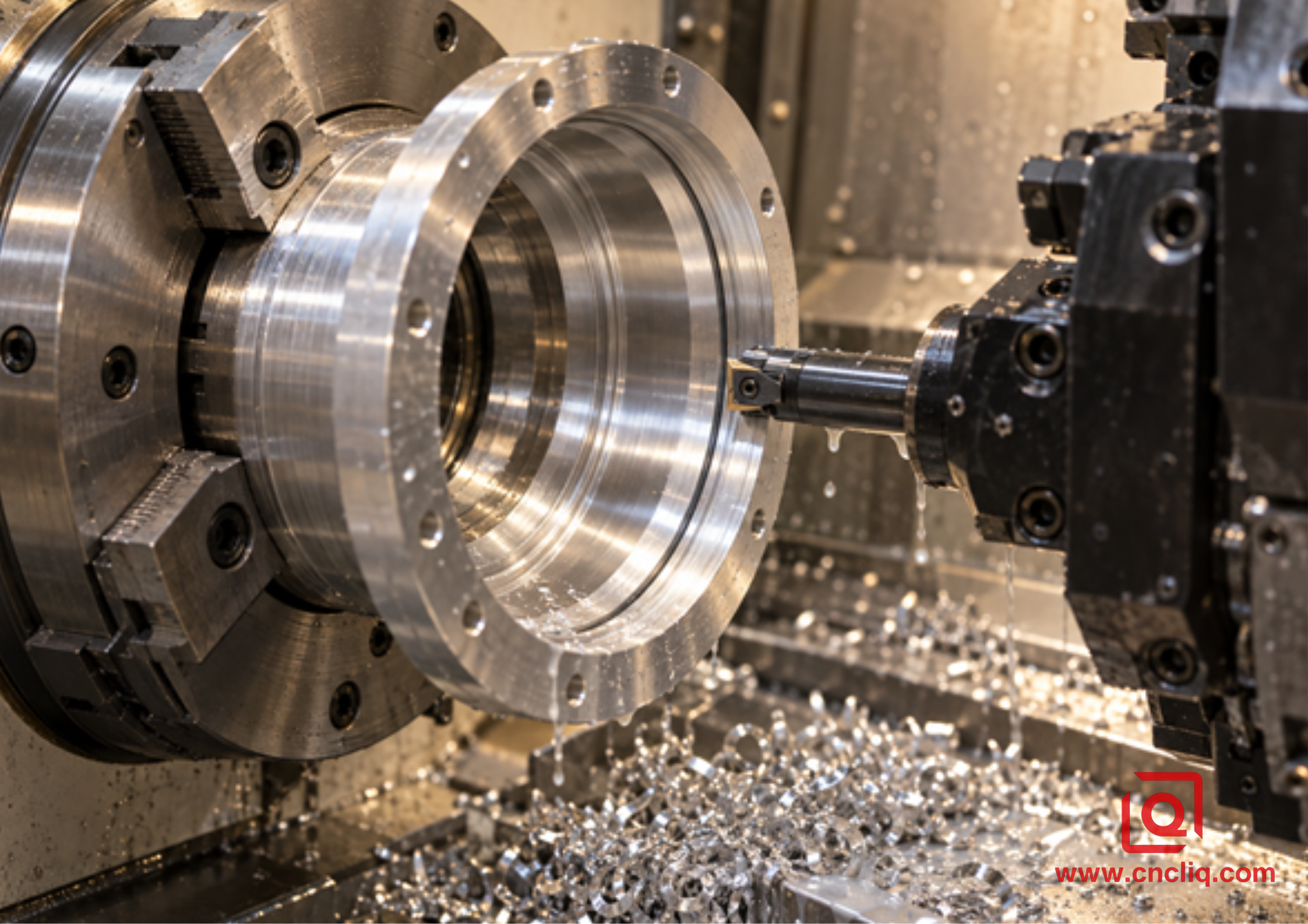
A conventional turning route is difficult to beat when the key requirements remain rotational and accessible in one chucking.
3. What Turn-Mill Multi-Tasking Adds
A turn-mill center combines turning with powered milling, drilling, boring, and tapping. Depending on configuration, it may add C-axis indexing, Y-axis motion, a B-axis tool spindle, an opposing spindle, or a lower turret. The useful phrase is not “more axes.” It is “fewer broken datum chains.” Okuma’s multi-tasking guide highlights setup reduction, improved accuracy, less human error, and reduced tolerance stack-up. Mazak similarly describes single-setup integration of turning, milling, drilling, tapping, and boring. Brother’s guide frames the concept as combining work that would otherwise require a lathe and machining center.
For a concentric aluminum housing, the main spindle can establish the bore and reference face; live tools can add cross-holes and flats while the part remains registered to that spindle; an opposing spindle can receive the work for backside access. The handoff is not automatically perfect. Spindle alignment, transfer force, jaw cleanliness, part-out length, and thermal condition still matter. Yet the transfer happens within a controlled machine coordinate system instead of through a cart, another fixture, and another manual alignment.
Turn-mill is not automatically cheaper. Programming takes longer, collision risk is higher, tool management is denser, and hourly cost is usually greater. It earns its place when it replaces enough setups, special fixtures, work-in-process handling, and reinspection—or when it protects a geometric requirement that would otherwise be fragile.
4. CNC Turning vs Turn-Mill: Practical Selection Table
|
Decision factor |
Conventional CNC turning route |
Turn-mill multi-tasking route |
|
Core geometry |
Best when critical features are primarily bores, ODs, faces, grooves, and threads. |
Best when rotational features interact with radial, off-center, angular, or backside details. |
|
Datum continuity |
Strong inside one chucking; weaker after transfer to a separate mill unless fixturing is qualified. |
Can keep turning and milling tied to one machine coordinate system; sub-spindle transfer still requires validation. |
|
Setup count |
Often 1 turning setup plus 1 or more milling setups. |
Often 1 integrated cycle, possibly including a programmed spindle handoff. |
|
Best batch profile |
Simple geometry, stable repeat volume, or low-volume work where secondary features are easy. |
High-mix complex housings, recurring batches, or any volume where geometric failure is costly. |
|
Fixture cost |
Lower for pure turning; custom rotary or soft-jaw fixtures may be needed for secondary work. |
Higher machine investment, but fewer separate fixtures and less handling. |
|
Inspection burden |
More intermediate checks may be needed after each setup. |
Fewer transitions, but first-article verification must cover handoff and cross-feature relationships. |
|
Typical risk |
Reclamping eccentricity, jaw distortion, datum mismatch, and handling marks. |
Complex programming, collision exposure, live-tool runout, thermal drift, and transfer misalignment. |
5. The Tolerance Chain That Usually Decides the Route
Imagine a compact sensor housing with a 52 mm lens bore, a 60 mm locating pilot, a face O-ring groove, 4 radial connector holes, and a rear threaded cap. The lens bore is datum A because it locates the optical stack. The mounting face is datum B because it seats the assembly. The radial holes are positioned relative to A and B so the connector pins align. If the bore and pilot are turned together, the turning portion is straightforward. The process decision rests on how the radial holes and rear thread relate to that same axis.
With a lathe-plus-mill route, the mill fixture must locate from the finished bore or a qualified pilot. Clamping on a thin OD may deform the very bore used as the datum. Locating on an unfinished casting surface is worse. A split sleeve, expanding mandrel, or bored soft jaw can work, but the fixture and its loading method become part of the process. If the hole position is forgiving, this is reasonable. If the positional zone is narrow and repeated around the circumference, keeping the part in a C-axis turn-mill cycle may remove the weakest link.
For broader context, Liqin’s guide to 3-axis, 5-axis, and mill-turn machining for custom aluminum parts explains how geometry changes machine choice. This article goes deeper on concentric housings by treating the datum axis as the central decision variable.
6. Aluminum-Specific Problems: Heat, Thin Walls, and Jaw Pressure
Aluminum cuts easily, but thin cylindrical sections move easily too. A machinist can measure an apparently round bore while it is clamped, then watch it relax after the jaws open. Three-jaw contact can create a subtle three-lobed condition. Too little force allows movement; too much force distorts the shell. The correct answer is not a universal chuck-pressure number. It depends on wall thickness, unsupported length, jaw contact area, alloy condition, stock variation, and cutting force.
Temperature also competes with tight tolerances. Published reference data for 6061 gives a typical thermal expansion coefficient near 23.2 × 10⁻⁶/°C over 20–100°C. As an illustration, a 100 mm diameter changing by 10°C changes by about 0.023 mm: ΔD = 23.2 × 10-6 × 100 mm × 10°C. This does not mean every part experiences a uniform 10°C rise, but it shows why a hot part, a warm spindle, and a cooler inspection room can create misleading readings when the tolerance band is narrow.
Useful controls include broad soft jaws, support close to the cut, balanced roughing, a pause before finishing when necessary, a light final pass, controlled coolant, and inspection after thermal stabilization. If anodizing follows, the drawing should identify whether dimensions apply before or after coating and which bores, threads, or sealing lands require masking. Liqin’s anodizing thickness and tolerance guide covers that downstream dimensional issue in more detail.
7. Process Plans That Work on the Shop Floor
Route A: Turning Center Plus Secondary Milling
Use this route when turning carries the tight requirements and the cross-features are moderate. Saw or prepare the blank, rough and finish the datum bore and reference face in one chucking, turn the external pilot and seal geometry, then transfer the part in protected trays. The mill fixture should locate from a finished functional feature, not a convenient raw surface. Qualify the fixture with an indicated master or first-off part; machine the holes, flats, and windows; then verify the relationship back to the turned datum.
This route can be highly capable. It is often the correct commercial choice for a housing with one radial connector, a loose bolt pattern, or a large envelope that does not fit the available turn-mill. It also isolates simple, fast turning from slower milled details, which can improve machine utilization in repeat production.
Route B: Main-Spindle Turn-Mill
Use this route when front-side rotational and radial features form one tolerance chain. Rough the bore and OD, equalize material removal, finish the datum bore and face, orient the C-axis, then drill, mill, and tap side features before unclamping. Toolpath order matters: do not finish a fragile bore and then apply an aggressive interrupted milling cut that springs the wall. Leave a deliberate final skim where needed.
Route C: Twin-Spindle Complete Machining
Use an opposing spindle when both ends carry related functional features. Complete the primary datum features on the main spindle, transfer with controlled pickup force, part off, then finish the rear bore, face, groove, or thread. Validate transfer runout during first-article approval and after any jaw or insert change that could disturb it. A single machine does not cancel physics; it makes the process easier to control and trace.
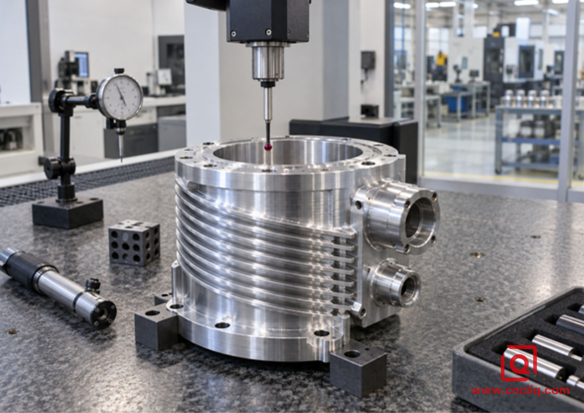
Inspection should follow the functional datum scheme: bore axis, mating face, then related pilots, grooves, ports, and patterns.
8. Inspection: Measure Function, Not Just Diameter
A micrometer can confirm OD. A bore gauge can confirm size and taper. Neither alone proves that the bearing seat, pilot, and seal face share the required axis and orientation. For a concentric housing, an inspection plan may combine bore gauges, air gauges for production bores, a roundness instrument where form is critical, a CMM for datum-related position and orientation, and a dial indicator or dedicated runout fixture for a fast functional check.
The ISO/TC 213 standards system includes the ISO 10360 family for CMM acceptance and reverification, while ISO 1101 defines the geometric specification language. Measurement method should match the drawing and use case. A few CMM points may miss a lobed bore; a continuous scan or dedicated form measurement may be justified. Conversely, scanning every cosmetic diameter adds cost without reducing functional risk.
Ask the supplier to agree on datum simulation, point density, filter strategy where applicable, measurement temperature, and reporting format before production. For ongoing batches, identify critical-to-quality features and a sampling plan. Liqin’s published precision motor flange/front end cap is a relevant product example because its bearing bore, locating spigot, and end face make concentricity and perpendicularity central to motor behavior.
9. Anonymized Case: Compact Motor Encoder Housing
An anonymized European automation customer requested a 6061-T6 encoder housing with 2 bearing seats, an external motor pilot, a face-seal groove, 3 radial cable features, and a rear threaded closure. This is a representative engineering scenario created to illustrate Liqin’s verified machining scope; commercial figures are intentionally omitted and it does not claim a universal capability value.
The early concept used a CNC lathe for the bores, pilot, and groove, followed by a separate VMC for the radial features. During DFM review, the team noticed that the thin cylindrical wall would have to be gripped again near a finished bearing seat. The drawing also tied the cable pattern to the bearing axis. The separate-mill route was feasible, but it required an expanding mandrel, a qualified angular stop, and a second geometric inspection sequence.
The selected route used a turn-mill center. The main spindle established the primary bearing bore, pilot, and seal face. C-axis live tooling machined the radial pattern before release. An opposing spindle supported backside completion. Roughing was balanced between inner and outer surfaces; final bearing passes occurred after the heavier cross-feature work. Inspection referenced the primary bore axis and mating face, then checked runout, perpendicularity, and the radial pattern. The key benefit was not a dramatic cutting-speed claim. It was removal of a high-risk reclamping step and a clearer control plan.
If your component has a similar tolerance chain, send the 3D model, 2D drawing, annual volume, alloy and temper, finish, and inspection expectations. Liqin can compare a turning-plus-milling route against integrated turn-mill instead of quoting a machine label in isolation.
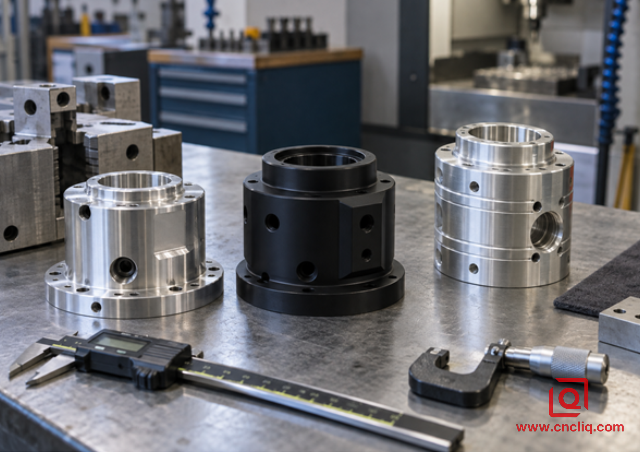
Different housing designs can favor different routes; the functional tolerance chain should make the decision.
10. How to Reduce Cost Before You Request a Quote
First, separate functional geometry from cosmetic geometry. Apply narrow runout, position, surface-finish, and size limits only where the assembly requires them. Second, identify the primary datum axis clearly. Third, supply both STEP and controlled 2D PDF files; the model communicates geometry, while the drawing communicates tolerances, finishes, notes, and acceptance criteria.
Also state batch size and annual demand. A 5-piece prototype may justify flexible soft jaws and extra inspection. A recurring order may justify dedicated jaws, preset tool packs, probing, or an automated bar process. Specify whether material certificates, coating reports, CMM data, or a full first article are needed. Liqin’s CNC machining RFQ checklist provides a broader submission guide, while the OEM aluminum CNC turning alloy guide helps when 6061, 6082, or 7075 is still under discussion.
Finally, allow the manufacturer to propose the route. “Must be made on turn-mill” is useful only when it expresses a validated requirement. If the drawing’s function can be met more economically on a turning center plus a qualified secondary fixture, the result—not the badge on the enclosure—is what the buyer receives.
11. RFQ Decision Checklist
|
Question |
If yes, what it suggests |
|
Can all critical features be turned in one chucking? |
Conventional CNC turning deserves first consideration. |
|
Do cross-holes, flats, slots, or ports have tight position relative to the bore axis? |
Turn-mill may protect datum continuity. |
|
Do both ends carry critical coaxial or runout-controlled features? |
Evaluate twin-spindle complete machining or a qualified second operation. |
|
Is the wall thin enough that reclamping can alter bore form? |
Reduce handling and review jaw contact, support, and cut sequence. |
|
Will coating change a fit, thread, or seal land? |
Define final-condition dimensions and masking before quotation. |
|
Is annual volume high enough to amortize programming and tooling? |
A multi-tasking route may gain value over recurring setups and WIP transfers. |
FAQs
1. Is turn-mill always more accurate than a conventional CNC lathe?
No. A rigid CNC lathe can produce excellent coaxial bores, diameters, faces, and grooves, often more economically. Turn-mill becomes valuable when milled or backside features must remain closely related to the turned datum axis. Machine condition, tooling, fixturing, thermal control, programming, and inspection determine actual capability; the machine category alone is not a guarantee.
2. When should a housing remain on a turning center plus a separate mill?
Use the split route when the critical tolerance chain is mostly rotational, secondary holes or flats have comfortable positional tolerance, and the part can be relocated without distorting the bore. It is also practical when the housing is too large for the available turn-mill or when production volume supports dedicated, repeatable secondary fixtures.
3. Which drawing callouts matter most for a concentric aluminum housing?
Identify the functional datum bore or pilot, the mating face, the size and fit of bearing or seal features, and the geometric relationships that affect rotation or assembly. Depending on function, use runout, position, perpendicularity, cylindricity, or profile rather than an informal blanket note. State whether requirements apply before or after anodizing.
4. Can a sub-spindle handoff introduce error?
Yes. Pickup-jaw condition, synchronization, transfer force, trapped chips, spindle alignment, unsupported length, and temperature can affect the second side. A capable process validates handoff runout during setup, controls jaw cleanliness and clamping, and includes the relevant backside-to-primary-datum relationship in first-article inspection.
5. What should I send for a reliable quotation?
Send a STEP model, controlled 2D drawing, material alloy and temper, finish specification, prototype and production quantities, annual demand, target schedule, critical-to-quality features, and reporting requirements. Explain what the bore, pilot, seal, and ports do in the assembly. That context lets the manufacturing engineer compare CNC turning and turn-mill routes intelligently.
Summary
CNC turning is the efficient first choice for a concentric aluminum housing whose important geometry remains rotational and accessible in one chucking; turn-mill multi-tasking becomes compelling when radial, angular, or backside features must stay tied to the same datum axis. The best route follows the tolerance chain, manages thin-wall and thermal behavior, and verifies function with an agreed inspection plan. Share complete drawings and application context early so Liqin can propose the safest, most economical process for your housing.
Contact Information
Company: Ningbo Liqin Industry Co., Ltd.
Daily customer maintenance & after-sales support:service@shturl. zhuwanying@cncliq.com
New inquiry, quotation & order discussion:business@shturl. zhouli@chinaliqin.com
Hotline: +86 18757148656
Disclaimer
All technical articles, material specifications, machining recommendations, and surface treatment details published on this blog are for informational and reference purposes only. Please note that general blog insights do not replace signed technical agreements. Because custom parts vary by material heat numbers, machine calibrations, and specific tolerances, binding quality specs are governed solely by your approved CAD drawings, signed contracts, and formal quality plans.
All customer case studies featured on this blog have been thoroughly anonymized and sanitized. The performance metrics, manufacturing workflows, and imagery displayed serve solely to demonstrate our custom machining capabilities and do not represent a single universal standard for all orders.
Liqin Manufacturing Team
Built on 18 years of precision engineering experience, Ningbo Liqin Industry manufactures high-tolerance metal components for demanding global markets. We operate out of a 6,500 m² production hub equipped with over 150 machines, running 4-axis and 5-axis CNC machining, mill-turn machining, cold extrusion, and pressure die casting under one roof. This setup allows us to manage projects seamlessly, taking parts from initial CAD concepts directly to finalized shipments.
We handle quality control with zero compromise. We treat tight tolerances with the engineering discipline they require. Backed by ISO 9001, ISO 13485, and IATF 16949 certifications, our QA engineers run strict IPQC, FQC, and OQC checks on every single production batch. From CMM dimensional mapping and optical profiling to hardness and salt-spray testing, we validate your critical specs upfront—so you receive drop-in ready components with zero assembly headaches or costly line stoppages. On top of manufacturing, you can rely on us for two-hour response times on new RFQs, direct support for prototype sampling, and smooth export shipping across Europe, North America, Asia, and Oceania.
Welcome your inquiries and samples. Visit our website or contact us directly for a competitive quote!
