 English




Key Takeaways
-
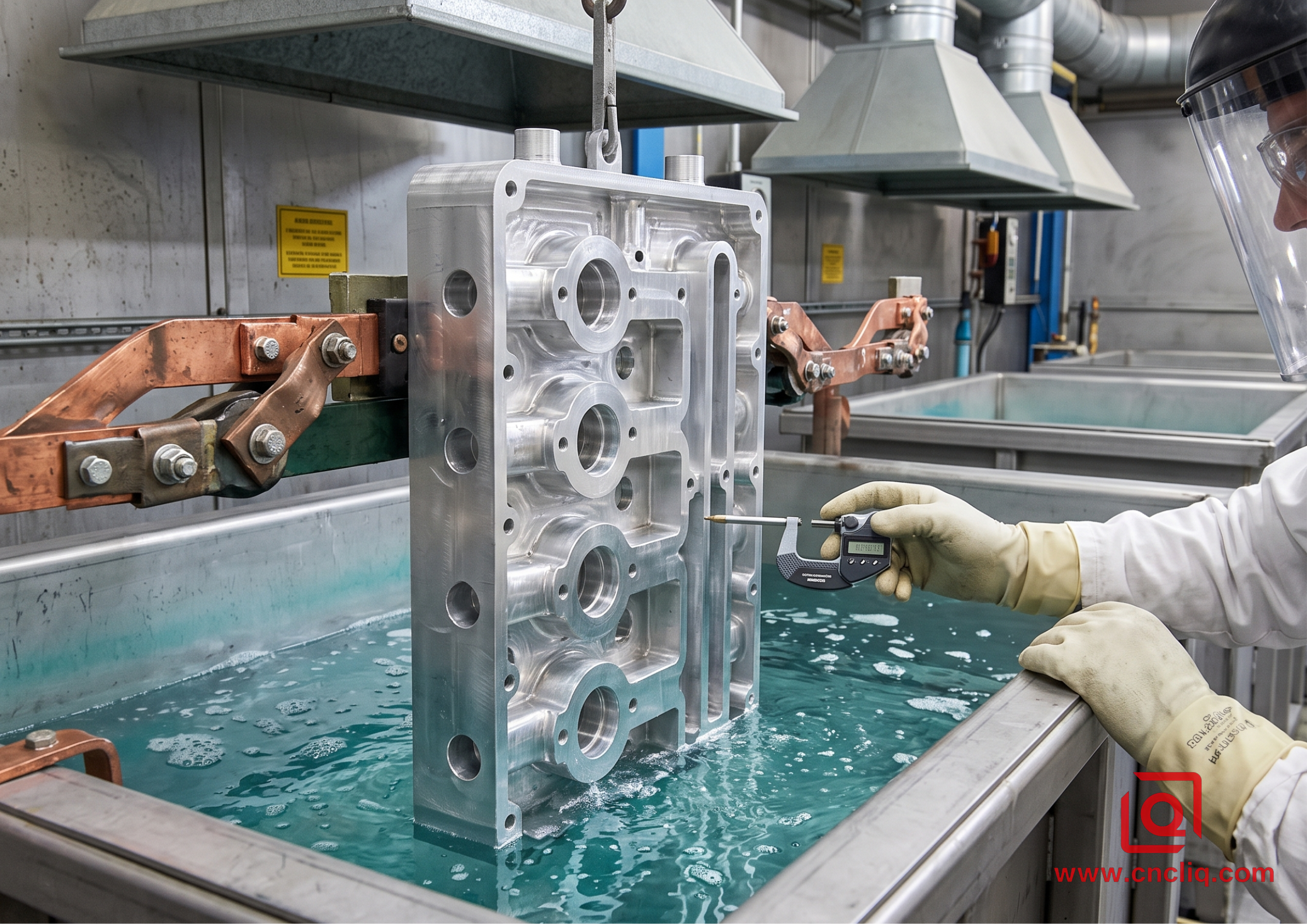
Dimensional Penetration-to-Growth Ratio: Sulfuric acid anodizing builds oxide layers by consuming raw metal depth (50%) while projecting outward (50%). A 20 µm total film increases radial part dimension by exactly 10 µm.
-
Pre-Machining Offset Calculation: Achieving an H7 clearance fit (+0.015/+0.000 mm) on 6061-T651 aluminum after Type III hard anodizing requires boring the internal diameter (ID) 0.020 mm oversize prior to dipping.
-
Thermal & Chemical Distortion Hazards: Leaving machined parts in ambient storage for over 6 hours under 65% or higher relative humidity forms an uneven natural hydroxide film, spiking local etching rates during acid pickling and blowing out bore tolerances by 8 µm.
-
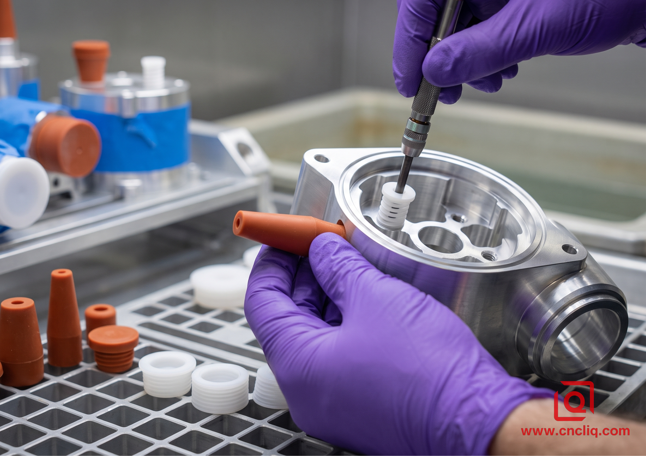
Precision Masking Interventions: Tapered silicone plugs combined with custom-milled PTFE threaded inserts eliminate post-anodize thread chasing operations and prevent stress-corrosion cracking along pitch diameters.
Why Does Anodizing Coating Build-up Impact Tight-Tolerance Aluminum OEM Components?
When CNC machinists pare down stock material on a 5-axis mill to hit tight ±0.005 mm drawing specifications, they often forget that the electro-chemical bath isn't a paint booth. It is a surface transformation process. Under MIL-A-8625F Type III hard anodizing, aluminum matrix atoms convert to ceramic Al2O3. This reaction eats into the base metal substrate by roughly half of the total layer thickness while expanding outward by the remaining half.
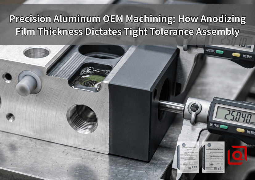
If your machinist turns a bearing journal on 7075-T6 aluminum down to 25.000 mm expecting a 25.000 mm finished outer diameter (OD), and then sends it to the anodizer for a 40 µm hard coat, the final outer diameter will measure 25.040 mm if you ignore metal consumption, or 25.020 mm if you track the true 1:1 growth ratio. Either way, that pressed bearing race will bind, gall, or outright fracture the housing during assembly.
       UN-ANODIZED SUBSTRATE                  POST-ANODIZED FINISH
+---------------------------------+   +---------------------------------+  <-- Outer Surface (+1/2 Thickness)
|                                 |   |   Al2O3 Ceramic Oxide Layer     |
|                                 |   |---------------------------------|  <-- Original Metal Interface
|      Solid Base Aluminum        |   |   Base Metal Consumed (-1/2)    |
|         (6061 / 7075)           |   |---------------------------------|
|                                 |   |      Solid Base Aluminum        |
+---------------------------------+   +---------------------------------+
In micro-actuator assemblies where internal slide clearances are locked at 6 µm to 10 µm, failing to factor in bath temperature variations, current density ramp rates, and dissolution speeds will ruin an entire batch. A 2°C temperature spike in a 180 g/L H2SO4 tank shifts the oxide dissolution rate enough to strip 4 µm off your critical features before the rectifier even shuts off.
How to Calculate Pre-Machining Dimensions for Anodized Aluminum Parts?
Stop dimensioning pre-anodized prints with standard tolerances and expecting the finishing floor to "work magic." You must engineer the pre-machined geometry using exact dimensional offset calculations based on targeted coating thickness, alloy metallurgy, and bath chemistry.
For external features (shafts, pins, mounting bosses):
Pre-Machined OD Target = Finished Nominal OD - (Specified Total Film Thickness x 0.50 x 2)
For internal features (bores, bushings, bearing pockets):
Pre-Machined ID Target = Finished Nominal ID + (Specified Total Film Thickness x 0.50 x 2)
Let’s look at a real shop-floor scenario: Machining a 6061-T651 hydraulic valve block housing with a target finished spool bore of 18.000 mm (+0.008/-0.000 mm) and a Type III Hard Coat spec of 30 µm ± 5 µm (non-colored, deionized water sealed).
1. Calculate Minimum Outward/Inward Growth (At Min Film = 25 µm):
   Single-side growth = 25 µm / 2 = 12.5 µm (0.0125 mm)
   Total ID constriction = 0.0125 mm x 2 = 0.025 mm

2. Calculate Maximum Outward/Inward Growth (At Max Film = 35 µm):
   Single-side growth = 35 µm / 2 = 17.5 µm (0.0175 mm)
   Total ID constriction = 0.0175 mm x 2 = 0.035 mm

3. Set Boring Bar Offset on CNC Lathe:
   Target Pre-Anodize Bore ID = 18.000 mm + 0.030 mm = 18.030 mm
   Pre-Anodize Machining Tolerance Window = 18.030 mm (+0.004 / -0.000 mm)
If your operator rough-bores this part and lets it sit on a pallet near an open bay door in humid weather for 4 hours, moisture absorption raises native surface oxidation from 0.04 nm to over 0.18 nm. When that part hits the caustic etch bath (NaOH, 50 g/L at 55°C), the acid strips the uneven oxide layer at variable rates, causing pit-corrosion patterns that ruin your Ra 0.4 µm surface finish and expand bore diameter by another 6 µm before anodizing even starts.
Parameter Reference Table: Machining Offset & Anodizing Process Matrix
| Parameter / Anodize Spec | MIL-A-8625F Type II (Class 1 Clear) | MIL-A-8625F Type III (Class 1 Hard Coat) | MIL-A-8625F Type III + PTFE Dope |
| Typical Target Layer Thickness | 10 µm (0.010 mm) | 40 µm (0.040 mm) | 50 µm (0.050 mm) |
| Outward Dimensional Growth (Per Side) | 5 µm (0.005 mm) | 20 µm (0.020 mm) | 25 µm (0.025 mm) |
| Substrate Metal Consumed (Per Side) | 5 µm (0.005 mm) | 20 µm (0.020 mm) | 25 µm (0.025 mm) |
| Total OD Expansion / ID Constriction | +0.010 mm / -0.010 mm | +0.040 mm / -0.040 mm | +0.050 mm / -0.050 mm |
| Pre-Machining Tolerancing Offset | +0.010 mm ID / -0.010 mm OD | +0.040 mm ID / -0.040 mm OD | +0.050 mm ID / -0.050 mm OD |
| Surface Roughness Impact (Delta Ra) | Increases Ra by 0.1 µm - 0.2 µm | Increases Ra by 0.4 µm - 0.8 µm | Increases Ra by 0.3 µm - 0.5 µm |
| Typical Tank Chemistry & Temp | 180 g/L H2SO4, 20°C, 1.5 A/dm² | 200 g/L H2SO4, 0°C-2°C, 3.6 A/dm² | 200 g/L H2SO4, 0°C, 3.6 A/dm² + PTFE Sub-micron |
| Microhardness Range (HV 0.05) | 250 HV - 350 HV | 400 HV - 600 HV | 350 HV - 450 HV |
| Recommended Applications | Decorative, Light Wear, Avionics Covers | Heavy Wear, High Friction, Linear Slides | Non-lubricated Valves, Precision Gearing |
Which Masking Strategies Prevent Thread and Bore Deformation During Anodizing?
You cannot allow hard anodizing solution inside tight M3 x 0.5 threaded blind holes or sub-millimeter pin locates. The build-up inside threads alters the pitch diameter geometry (6H fit standards). Force-threading a stainless steel fastener into an anodized aluminum thread instantly causes galling, snapping the bolt head clean off at 1.2 Nm torque.
                  PRECISION MASKING INTERVENTION

            [Silicone Pull Plug / Custom PTFE Insert]
                             ||
     +-----------------------||-----------------------+
     |                       ||                       |
     |   ====================||====================   |
     |  |   Protected Threaded ID (Uncoated)     |  |  <-- Zero Acid Ingress
     |   ====================||====================   |  <-- Pitch Diameter Preserved
     |                       ||                       |
     |     6061-T6 / 7075-T6 Aluminum OEM Body        |
     |                                                |
     +------------------------------------------------+
Step-by-Step Masking Protocols for OEM Shop Floor:
-
De-grease and Ultrasonic Clean: Wash parts in an alkaline detergent at 60°C for 12 minutes. Rinse twice in deionized water (< 10 µS/cm conductivity).
-
Install Custom-Milled PTFE Screws for Threaded Holes: Do NOT use standard rubber plugs for deep blind threads. Residual air trapped inside blind holes expands when submerged in 20°C acid tanks, blowing the plug out mid-cycle. Use vented PTFE threaded plugs with EDPM O-rings. Screw them in using a torque-limiting driver set to 0.4 Nm.
-
Apply Tapered EPDM Plugs for Precision Bearing Bores: Push high-temp tapered plugs through internal bores until the sealing ring sits 0.5 mm past the chamfer edge. This prevents "shadowing" or under-plating along the bore lip.
-
Post-Anodize Inspection via Thread Gauges: Pull plugs out immediately after the final hot water seal (96°C-100°C nickel acetate, 15 min). Verify pitch clearance using a GO/NO-GO 6H thread plug gauge. If acid bled past the plug, do NOT chase the thread with a tap! Tapping anodized threads breaks the tool's carbide teeth against the hard oxide coating (600 HV). Chemically strip the local oxide layer using a controlled 30 g/L chromic acid / 35 mL/L phosphoric acid solution heated to 100°C before re-tapping.
Real-World Case Study: High-Speed Optical Housing Defect Elimination
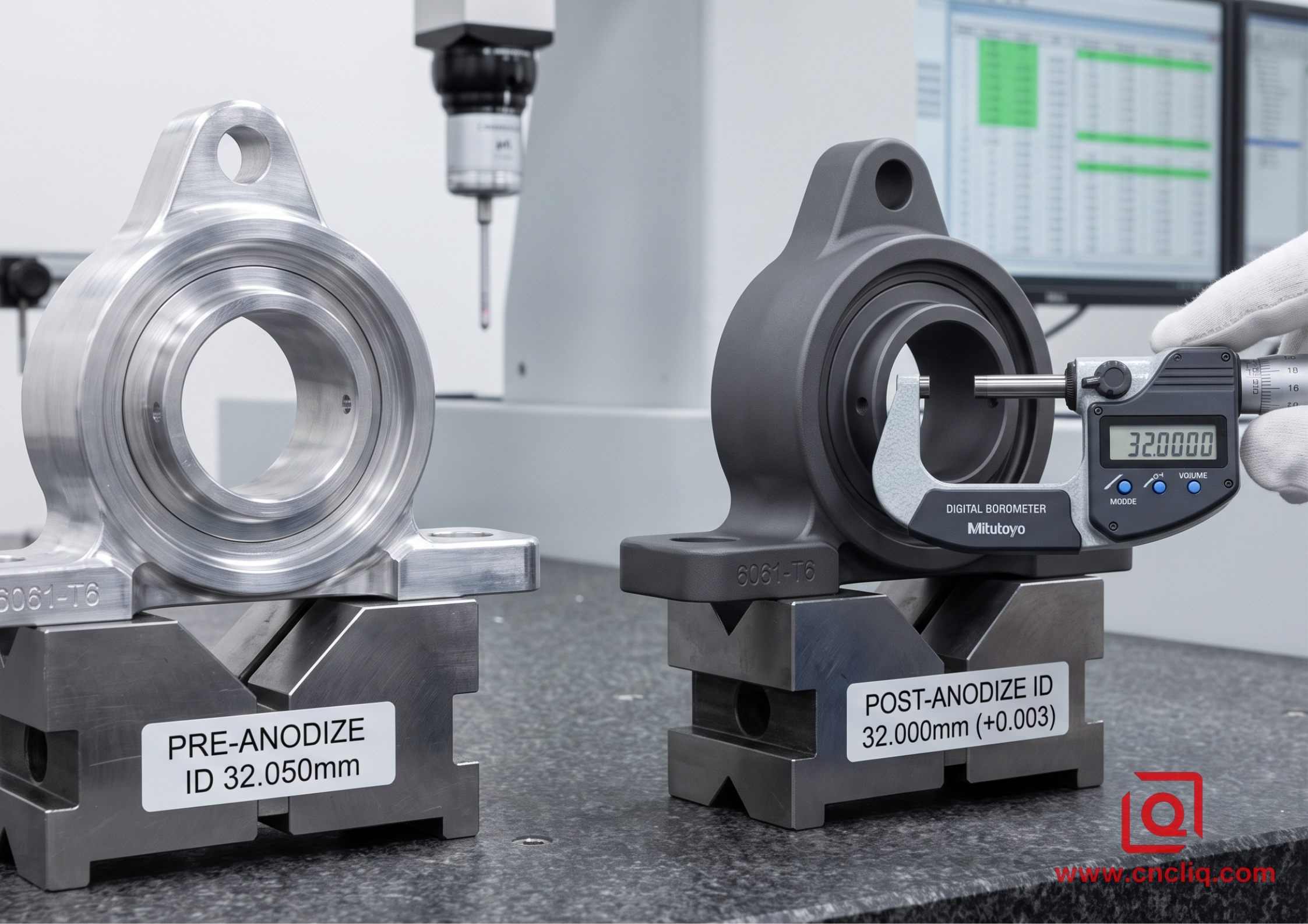
A Tier-1 medical equipment builder needed 500 units of a 7075-T6 CNC-turned sensor housing. Critical callout: Bearing journal bore diameter at 32.000 mm (+0.005/-0.000 mm), with a 50 µm Type III Hard Anodize spec for wear resistance against linear ball cages.
Initial Vendor Failure:
The previous machine shop turned the bore directly to 32.000 mm, assuming the plating shop would "apply a thin 0.005 mm coating." The tank operator ran the parts under a standard 3.6 A/dm² constant current density for 60 minutes.
Result? Total film thickness hit 52 µm. Growth per side was 26 µm, shrinking the final bore to 31.948 mm. The parts were 0.052 mm undersized. When the customer tried pressing the linear bearings in, 100% of the housings cracked along the thin-wall stress lines.
Our Engineering Corrective Action:
-
Machining Adjustment: Re-calculated pre-anodize bore ID target: 32.000 mm + (0.050 mm nominal film x 0.50 x 2) = 32.050 mm. Set CNC lathe boring operation to 32.050 mm (+0.003/-0.000 mm).
-
Surface Finish Tuning: Pre-anodize boring produced Ra 0.2 µm. Knowing that Type III hard coat increases surface roughness by roughly 0.5 µm on 7075-T6, we added a roller burnishing step on the lathe, dropping pre-finish roughness down to Ra 0.08 µm.
-
Tank Ramp Rate & Temperature Lockdown: Chilled the sulfuric acid tank down to 0°C ± 0.5°C. Programmed the rectifier for a 10-minute current density ramp from 0.5 A/dm² up to 3.2 A/dm² to prevent thermal shock and micro-cracking in the high-zinc alloy matrix.
-
Metrology Inspection: Measured coating thickness using an eddy-current probe (conforming to ISO 2360 / ASTM B244) at 8 multi-axis points inside the bore. Total layer thickness registered at 50.2 µm ± 1.2 µm.
Final CMM Results: Finished bore diameter measured 32.000 mm to 32.003 mm across all 500 parts (Cpk = 1.82). Assembly scrap dropped from 100% down to 0%. Total turnaround time reduced by 3 days by removing off-site thread chasing and manual honing.
FAQs
Q1: How does anodizing film thickness affect the ultimate assembly clearance between an aluminum housing and a steel shaft or bearing?
A: Anodizing is an conversion process where oxide layer growth occurs half below the original metal surface and half above it. A specified total coating thickness of 40 µm increases radial dimensions by 20 µm per side, which shrinks an internal bore diameter by 0.040 mm and expands a shaft diameter by 0.040 mm. If machinists do not apply a pre-machining dimensional offset, the effective assembly clearance decreases by 0.040 mm, causing bearing press-fit binding or premature housing fracture.
Q2: Can we adjust or tap aluminum threads after Type III hard anodizing to fix out-of-tolerance pitch diameters?
A: No, never re-tap anodized threads using standard carbide or HSS taps. The aluminum oxide coating created under Type III hard anodizing achieves a surface hardness of 400 HV to 600 HV, which instantly dulls or breaks tap cutting teeth upon contact. If thread pitch diameters become tight, you must chemically strip the localized oxide layer using a heated solution of 30 g/L chromic acid and 35 mL/L phosphoric acid at 100°C before running a thread chase operation.
Q3: Why do 6061-T6 and 7075-T6 aluminum alloys exhibit different coating growth rates in the same anodizing tank?
A: Alloying elements directly alter electrical conductivity and anodizing kinetics. High-zinc alloys like 7075-T6 exhibit higher intermetallic electrical resistance compared to silicon-magnesium 6061-T6, leading to increased local heat generation and dissolution rates. At a constant current density of 3.6 A/dm², 7075-T6 requires tighter tank temperature control (0°C ± 0.5°C) and progressive ramp rates to achieve the same target film thickness without micro-cracking or burning.
Q4: What is the most effective masking method to protect sub-millimeter blind holes during hard anodizing?
A: Vented PTFE threaded plugs fitted with EPDM O-rings provide superior sealing over standard silicone push plugs. In deep blind holes, air trapped beneath non-vented rubber plugs expands due to temperature shifts in 20°C pretreatment tanks, forcing the plug out mid-cycle. Threaded PTFE inserts installed to 0.4 Nm torque maintain zero-leak seals, fully protecting internal M3 or M4 thread profiles from acid contact while preserving pitch diameter tolerances.
Q5: How does surface roughness (Ra) change before and after Type III hard coat anodizing on precision OEM components?
A: Hard anodizing increases surface roughness because the anodic oxide cell structures grow at micro-angles relative to the grain boundary orientation. On 6061-T6, a 40 µm hard coat typically increases surface roughness by Delta Ra 0.4 µm to 0.8 µm. For precision bearing bores requiring a finished Ra 0.4 µm, pre-anodize CNC turning or boring operations must achieve Ra 0.08 µm to 0.1 µm through roller burnishing or micro-honing prior to chemical processing.
Summary
In precision aluminum OEM manufacturing, anodizing is not a cosmetic final touch—it is a dimensional transformation that directly dictates assembly success. Achieving tight-tolerance fit specs like H7 requires mastering the 1:1 oxide growth-to-consumption ratio, establishing precise CNC pre-machining offset calculations, and enforcing strict shop-floor protocols around tank temperatures, current ramps, and thread masking. By engineering pre-machining dimensions around targeted film thickness rather than reacting to post-plating error, OEM suppliers can eliminate assembly binding, prevent thread galling, and guarantee repeatable Cpk performance across high-precision runs.
Contact Information
Disclaimer
All technical articles, material specifications, machining recommendations, and surface treatment details published on this blog are for informational and reference purposes only. Please note that general blog insights do not replace signed technical agreements. Because custom parts vary by material heat numbers, machine calibrations, and specific tolerances, binding quality specs are governed solely by your approved CAD drawings, signed contracts, and formal quality plans.
All customer case studies featured on this blog have been thoroughly anonymized and sanitized. The performance metrics, manufacturing workflows, and imagery displayed serve solely to demonstrate our custom machining capabilities and do not represent a single universal standard for all orders.
Liqin Manufacturing Team
Built on 18 years of precision engineering experience, Ningbo Liqin Industry manufactures high-tolerance metal components for demanding global markets. We operate out of a 6,500 m² production hub equipped with over 150 machines, running 4-axis and 5-axis CNC machining, mill-turn machining, cold extrusion, and pressure die casting under one roof. This setup allows us to manage projects seamlessly, taking parts from initial CAD concepts directly to finalized shipments.
We handle quality control with zero compromise. We treat tight tolerances with the engineering discipline they require. Backed by ISO 9001, ISO 13485, and IATF 16949 certifications, our QA engineers run strict IPQC, FQC, and OQC checks on every single production batch. From CMM dimensional mapping and optical profiling to hardness and salt-spray testing, we validate your critical specs upfront—so you receive drop-in ready components with zero assembly headaches or costly line stoppages. On top of manufacturing, you can rely on us for two-hour response times on new RFQs, direct support for prototype sampling, and smooth export shipping across Europe, North America, Asia, and Oceania.
Welcome your inquiries and samples. Visit our website or contact us directly for a competitive quote!
