 English




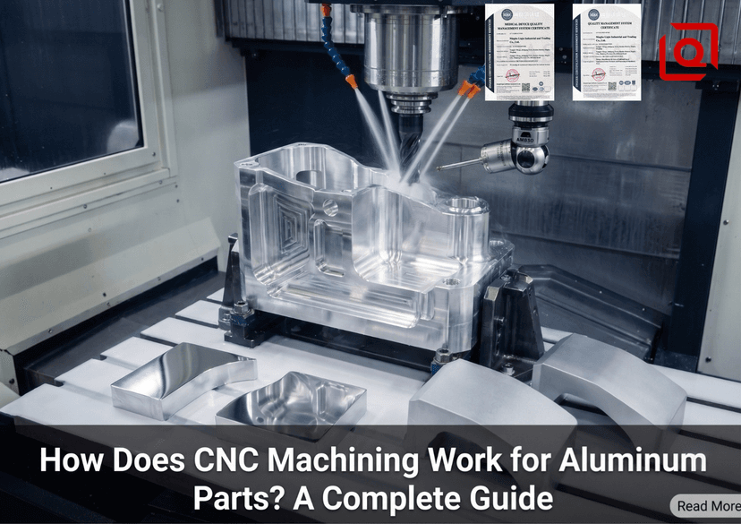
Forget the boilerplate CAD-to-CAM primers written by content marketers. If you are milling 6061-T6 plate or forged 7075-T651 billets on a shop floor, you know the daily grind: you hang an unsupported 1.2mm thin wall, dial up the spindle to 18,000 RPM, and watch your X/Y coordinate axes drift by 0.035mm because ambient heat soaked into the fixture, or built-up edge (BUE) galling micro-welded onto your uncoated carbide end mill flutes. Aluminum machining looks forgiving on paper due to low shear yield strength—until you run into severe cutter chatter, wall deflection, residual stress bow, or anodizing color-band shifts caused by tramp oil contamination in your coolant sump.
Shop Floor Reality Check: The Thermal Expansion Trap
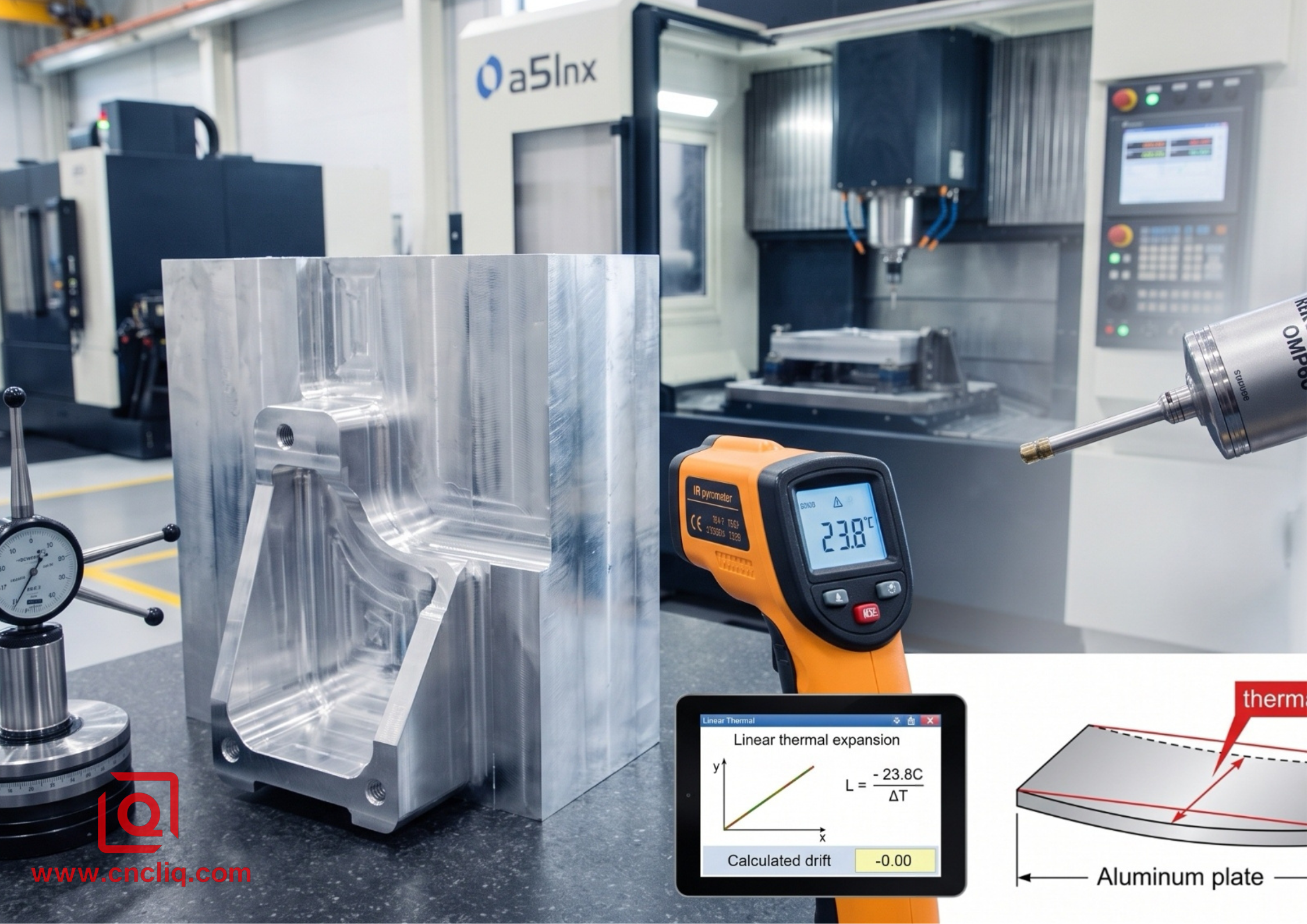
At a coefficient of linear thermal expansion of 23×10-6/K , a 300mm 6061-T6 structural bracket swells 0.034mm across a modest 5°C ambient shift inside an unconditioned machine shop. If your CMM inspection lab sits at a controlled 20°C ISO 1 standard, but your coolant bath ran at 27°C during the final finishing pass, you just machined a scrap part. Period.
1. What is CNC Aluminum Machining? (Engineering Physics Level)
At its physical core, cutting aluminum alloys isn't about brute shearing force like P20 or H13 tool steel; it's about ultra-high chip load evacuation, friction control, and structural attenuation of high-frequency harmonics. High-speed machining (HSM) of aluminum relies on shearing material faster than thermal energy can diffuse from the shear zone into the workpiece substrate.
When running a Makino a51nx horizontal machining center or a 5-axis Hermle C42, aluminum machining demands specific cutter dynamics: high rake angles (15° to 20°), polished flute flutes (Ra<0.1μm) to prevent aluminum adhesion, and dynamic chip thinning strategies where feed rates exceed 0.15mm/tooth at surface speeds (Vc) above 600m/min.
2. Step-by-Step Machining Workflow: Billet to Finished Component
Here is the actual shop-floor execution sequence used for structural packaging machinery brackets and aerospace fluid manifolds:
-
Billet Stress Relieving & Pre-conditioning: Raw extruded 6061-T6 block (300mm×150mm×50mm). Stock material holds internal rolling stress. Rough face mill 1.5mm off all six faces, then unclamp entirely from the vise. Let the block breathe for 30 minutes. Skip this, and residual stress will warp your datum surfaces by up to 0.12mm right after pocketing.
-
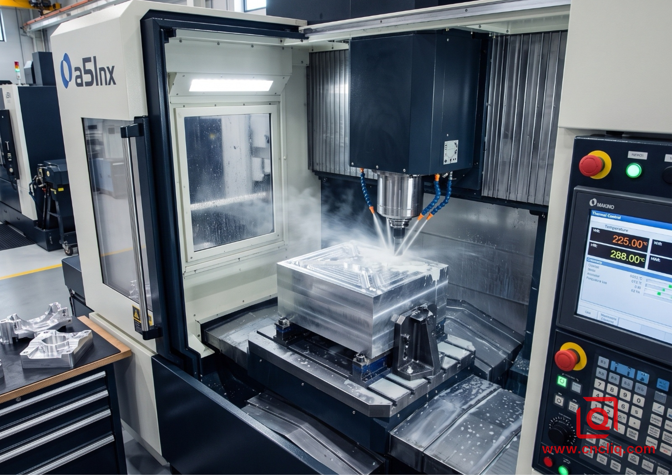
OP10 Heavy Roughing (Volumetric Trochoidal Milling): Load a 3-flute Ø12mm DLC-coated (Diamond-Like Carbon) solid carbide end mill. Stickout: 30mm. Parameters: S=14,000RPM, F=4,200mm/min, ap =18mm(axial depth), ae =1.2mm(radial engagement). Maintain constant 80 bar high-pressure through-spindle coolant (TSC) with an 8% water-soluble synthetic emulsion concentration.
-
OP20 Semi-Finishing & Thermal Stabilization: Measure part temperature with an IR pyrometer. Must read <24℃. Execute finishing on critical alignment bores using a digital micro-boring head at Vc=450m/min, feed f=0.04mm/rev. Leave 0.08mm stock for final skim pass.
-
OP30 High-Speed Wall & Floor Skim Finishing: Swap to a 2-flute single-crystal diamond (SCD) or polished uncoated carbide end mill with a 0.4mm corner radius. Sweep floor at ap =0.1mm, stepover Wf =65%D. Maintain surface roughness Ra≤0.4μm directly off the tool.
-
Deburring & Ultrasonic Degreasing: In-machine thermal deburring or automated brush pass (180-grit ceramic bristle). Ultrasonic tank immersion at 60°C in alkaline surfactant bath for 12 minutes to strip hydrocarbon residues before CMM probe contact.
3. Process Execution & Parameters Matrix
| Process Step | Target Parameters / Machinery | Dominant Failure Mode | Shop Floor Preventive Action |
| Stock Preparation | 6061-T651 / 7075-T6511 extruded bar stock; bandsaw cut + 1.0mm margin | Raw stock bow / twist exceeding 0.25mm | Specify T651 / T6511 stress-relieved temper (stretched 1.5–3% prior to delivery) |
| OP10 Rough Milling | Ø12mm 3-Flute Carbide; Vc=550m/min, fz=0.1mm,ap = 1.5D | Flute clogging / BUE micro-welding | 80 bar TSC directed down tool flutes; maintain emulsion concentration at 8.5% |
| Thin-Wall Finishing | Ø6mm 2-Flute Polished; Vc = 700m/min, fz=0.03mm, step-down 0.5mm | High-frequency chatter marks (Ra>1.6μm) | Ramp down axial depth (ap), use variable helix angle end mills (37°/40° combo) |
| Thread Tapping | M6×1.0 Roll Form Tap (Thread Forming); S=1,800RPM | Tap breakage from chip packing in blind holes | Use thread forming taps instead of cutting taps; pre-drill hole diameter to Ø5.52mm (±0.01) |
| CMM Verification | Zeiss SPECTRUM CMM; Renishaw VAST XXT probe; 20°C ±0.5℃ ambient | False out-of-roundness readings on thin bores | Allow 2 hours thermal equilibration in CMM room before touching off datums |
4. Post-Machining Surface Finishing Options
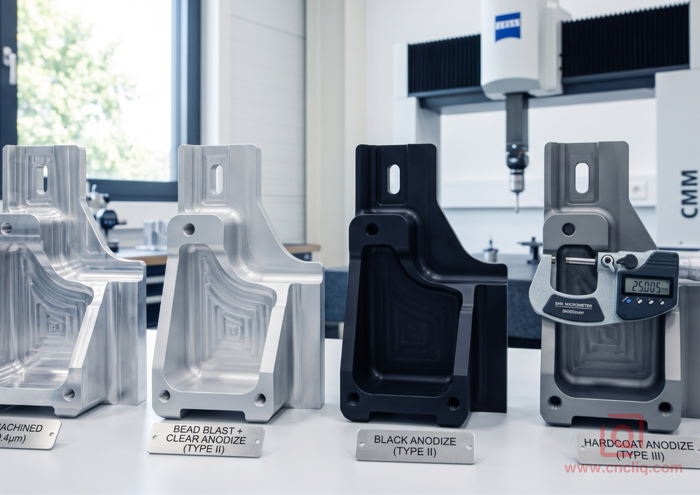
Raw CNC aluminum oxidizes naturally, but for industrial field deployment, raw aluminum is unacceptable. The surface treatment selection directly alters dimensional tolerances:
-
Type II Sulfuric Acid Anodizing (MIL-A-8625 Type II): Coating thickness: 8–12µm. Adds approx. 4–6µm per side dimensional growth. Color dyes (Black, Clear, Blue). Increases surface hardness to ~300 HV.
-
Type III Hardcoat Anodizing (MIL-A-8625 Type III Class 1/2): Coating thickness: 50µm ±5µm (25µm growth into metal, 25µm buildup on surface). Surface hardness hits 60–65 HRC (600+ HV). Precision threads must be pre-chased or under-cut by 0.05mm prior to Type III hardcoat!
-
Chromate Conversion / Chemical Film (MIL-DTL-5541F Class 1A & Class 3): Barely measurable thickness (<1μm). Preserves electrical conductivity (Class 3) while offering baseline salt-spray corrosion resistance (168 hours per ASTM B117).
-
Bead Blasting + Anodize: Glass bead size #10 (70–140 mesh) at 0.4 MPa blast pressure. Eliminates tool marks (Ra flattens to ~1.2–1.6µm), yielding a satin matte finish.
FAQs
Q1: What is the tightest achievable CNC tolerance for aluminum parts in production?
A: On temperature-stabilized 5-axis machining centers with in-situ Renishaw OMP60 probing, we routinely maintain ±.006mm on hole center distances and H7 (+0.012/-0.000mm) bore limits. However, holding <0.005mm requires grinding or hone-lapping post-process.
Q2: Why do aluminum parts bow upward after milling deep pockets?
A: Extruded and cold-rolled billets harbor internal residual tensile stresses. When you mill away 70% of the top mass, the asymmetric stress field relaxes, causing the remaining bottom web to bow up. Solution: Use stress-relieved T651 stock, rough both sides symmetrically, or perform an intermediate stress-relief anneal (160°C for 2 hours) between roughing and finishing passes.
Q3: How do you prevent thread galling or tap breakage when machining deep M2–M4 blind holes in 6061-T6?
A: Ditch conventional spiral-flute cutting taps entirely. Switch to cobalt-alloy thread forming (roll) taps paired with a synthetic oil emulsion at 10% concentration. Pre-drill the pilot hole precisely using a solid carbide drill to Ø1.82mm (for M2×0.4) or Ø3.68mm (for M4×0.7) within a ±0.008mm tolerance window. Running a cutting tap into a deep blind hole causes stringy aluminum swarf to pack the flutes, inducing torsional spike loads exceeding 3.5 N·m that snap the tool instantly. Roll forming cold-works the thread flanks, eliminating chips entirely while boosting thread shear strength by up to 15%.
Q4: What is the optimal strategy to control dimensional drift during 24-hour unmanned lights-out machining of aluminum parts?
A: Unmanned overnight runs will drift—period. You must attack thermal expansion simultaneously across machine kinematics, coolant heat-soak, and spindle growth. Program an automated macro every 45 minutes to grab an in-situ Renishaw OMP60 probe and execute a rapid 3-point touch-off against a fixed ceramic datum sphere, dynamically recalculating your G54 work coordinate origin before thermal drift destroys part tolerances. Lock the oil-water emulsion tank within ±0.5℃ of ambient using a closed-loop coolant chiller, and run a laser tool setter (e.g., Blum NC4) to catch spindle cartridge thermal growth at 20,000 RPM, automatically updating tool length offsets the second Z-axis drift creeps past 0.003mm.
Q5: What is the optimal strategy to control dimensional drift during 24-hour unmanned lights-out machining of aluminum parts?
A: Thermal compensation must be tackled on three fronts: machine kinematic growth, coolant heat-soak, and in-process tool wear. Program an automated macro every 45 minutes to execute a quick 3-point touch-off on a fixed ceramic datum sphere using an in-situ Renishaw OMP60 probe, recalibrating machine axis thermal offsets (G54 dynamic origin update). Additionally, install a closed-loop coolant chiller maintaining the oil-water emulsion tank within ±0.5℃ of ambient, and apply laser tool setters (e.g., Blum NC4) to detect tool tip growth (>0.003mm) caused by spindle thermal expansion at 20,000 RPM.
Summary
Mastering precision CNC aluminum machining isn't just about spinning a spindle at high RPMs—it demands rigorous thermal management, precise chip load evacuation, and strategic stress-relief protocols at every phase. By selecting the correct temper (such as 6061-T651), applying high-pressure through-spindle coolant (TSC), utilizing proper tool geometries, and strictly accounting for post-finish plating growth (MIL-A-8625 Type II/III), you can consistently eliminate wall deflection, chatter, and micro-welding failures while holding sub-ten-micron tolerances.
Contact Information
Disclaimer
The parameters and guidelines herein are for general reference only. Actual machining results depend on specific part designs, material grades, and operating conditions. Liqin Industrial & Trading Co., Ltd. assumes no liability for application performance based solely on this content. Please submit your CAD files (STEP/IGES) to our engineering team for precise DFM review and quotes.
Liqin Manufacturing Team
We are Ningbo Liqin Industrial & Trading Co., Ltd.,a professional manufacturer with over 18 years of experience in high-precision custom metal parts. We specialize in CNC machining, forging, die casting, and cold extrusion processes, serving industries such as automotive, medical, aerospace, electronics, and more. Our factory covers an area of 6,500 square meters and is equipped with 150+ advanced machines, including:
- CNC machining centers (4-axis, 5-axis)
- CNC lathes and turning-milling complexes
- Cold extrusion equipment (250T–650T)
- Die casting machines
We adhere to ISO9001, ISO13485: 2016, and IATF16949: 2016 standards, implementing end-to-end quality management: In-process quality control (IPQC), final quality control (FQC), outgoing quality control (OQC). CMM, projectors, hardness testers, and salt spray test equipment. Our products are exported to North America, Europe, Asia, and Oceania. We offer:
- One-stop service from design to delivery
- Quick response within 2 hours for quotes and technical support
- Custom solutions based on your drawings or samples
Welcome your inquiries and samples. Visit our website or contact us directly for a competitive quote!
