 English




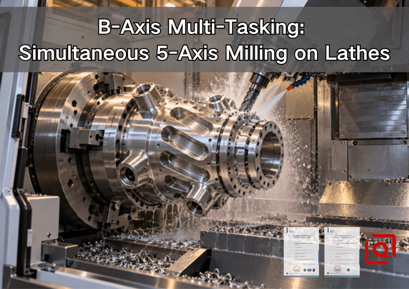
Are you still moving a turned component to a machining center because one angled port or curved feature sits beyond the reach of a fixed live tool? It is a familiar headache. The part leaves a reliable spindle datum, waits for another machine, and returns with a new fixture and a new chance for runout. This article looks at the alternative: B-axis multi-tasking on a lathe, including 5-axis milling. We will explain what the axes actually do, where the process is worth the cost and what details a supplier needs before giving a quote.
There is one point to make at the start. More axes do not automatically make a better process. A B-axis is helpful when it maintains a relationship or reaches geometry that a simpler way cannot handle properly. If the drawing only needs two cross-holes and a wrench flat ordinary live tooling may be the solution.
1. What Moves on a B-Axis Mill-Turn?
Picture the machine with the doors open. The workpiece is clamped on the lathe centerline. X moves the tool radially, Z follows the spindle axis, C controls spindle angle, and Y moves the cutter off center. Above the work sits a milling spindle that can swivel. That swivel is B.
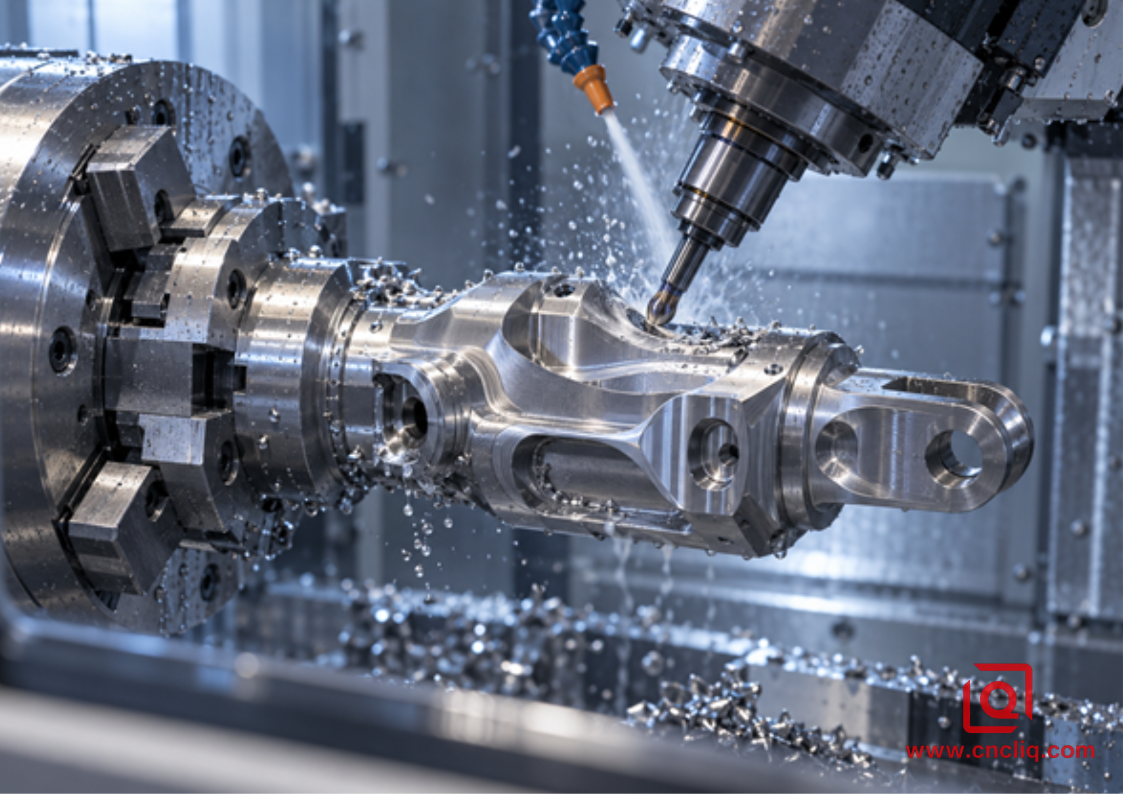
During a simultaneous cut, X, Y, and Z move the cutter tip. B changes the tool angle, while C rotates the workpiece to present the next surface. In a 3+2 operation, B and C index to a fixed angle and then stay still while the linear axes cut. Both methods are useful. They solve different problems.
Machine builders make the same distinction. DMG MORI describes turn-mill platforms that combine turning with 5-axis and simultaneous 5-axis milling, including free-form work on the main or counter spindle. Okuma's MULTUS arrangement places a swiveling milling head above a turning spindle and supplies tools from a magazine. A powered turret with C-axis indexing may still be called a mill-turn, so ask about the actual axis configuration.
Our guide to live tooling on CNC lathes covers the step below a B-axis machine. That guide is useful when the part needs surfaces, holes or radial threads but does not need the tool angle to change.
|
Motion |
What the machinist uses it for |
Useful RFQ question |
|
X, Y, Z |
Places the cutter in space |
Can Y reach the most distant off-center feature? |
|
B |
Tilts the milling spindle |
Is B continuously controlled or position-only? |
|
C |
Orients or rotates the workpiece |
Can C interpolate smoothly while cutting? |
|
Main spindle |
Holds the primary turning datum |
Which bore, journal, or face is the master? |
|
Counter spindle |
Receives the part for back work |
How will transfer runout be checked? |
2. 3+2 or Simultaneous 5-Axis? Look at the Feature
On the shop floor most work, on the B-axis doesn't involve all five axes moving once like a dance. Often it's indexed machining. The head tilts to an angle the C-axis turns the part into position. Then standard milling begins. This method is stable easy to check and usually cheaper to set up.
Use this approach for a connector pad, a bore with a bolt pattern on a surface or a few faces around a curved shape. There's no benefit, in keeping the B-axis moving when the feature being machined doesn't need it.
Simultaneous motion is saved for features. Think of a recess that wraps behind a flange a passage that flows smoothly a surface shaped by the side of a tool or a sculpted pad where the surface direction keeps changing. Here the tool needs to tilt while it moves. The C-axis might also turn the part so the cutting edge stays clear of the chuck the shoulder and the finished areas.
This difference changes everything. Simultaneous paths require a trusted postprocessor, a machine model, calibrated axes, code-level simulation and time spent proving the part. Only use them when they solve an access or surface quality issue. Our full comparison of 3-axis, 5-axis, and mill-turn machining can help with choosing the machine.
|
Part requirement |
Live-tool C-axis |
3+2 B-axis |
Simultaneous 5-axis |
|
Radial hole or simple bolt circle |
Usually enough |
Possible, often excessive |
Not justified |
|
Straight port at one compound angle |
Holder-dependent |
Usually the best fit |
Rarely needed |
|
Several separate angled faces |
Limited |
Strong fit |
Only for blended transitions |
|
Continuous free-form surface around a turned body |
Poor fit |
Leaves indexed zones |
Strong fit |
|
Tool angle must change to clear a shoulder |
Poor fit |
Cannot maintain clearance |
Strong fit |
3. The Real Prize Is a Shorter Datum Chain
Consider a housing with a bore, a sealing face, and an angled sensor pocket. The pocket position is controlled back to that bore and face. A conventional route turns the bore, releases the part, and locates it again in a milling fixture. A good fixture can do the job. The second setup adds its jaw pressure, chips under locators, pickup error and operator variation.
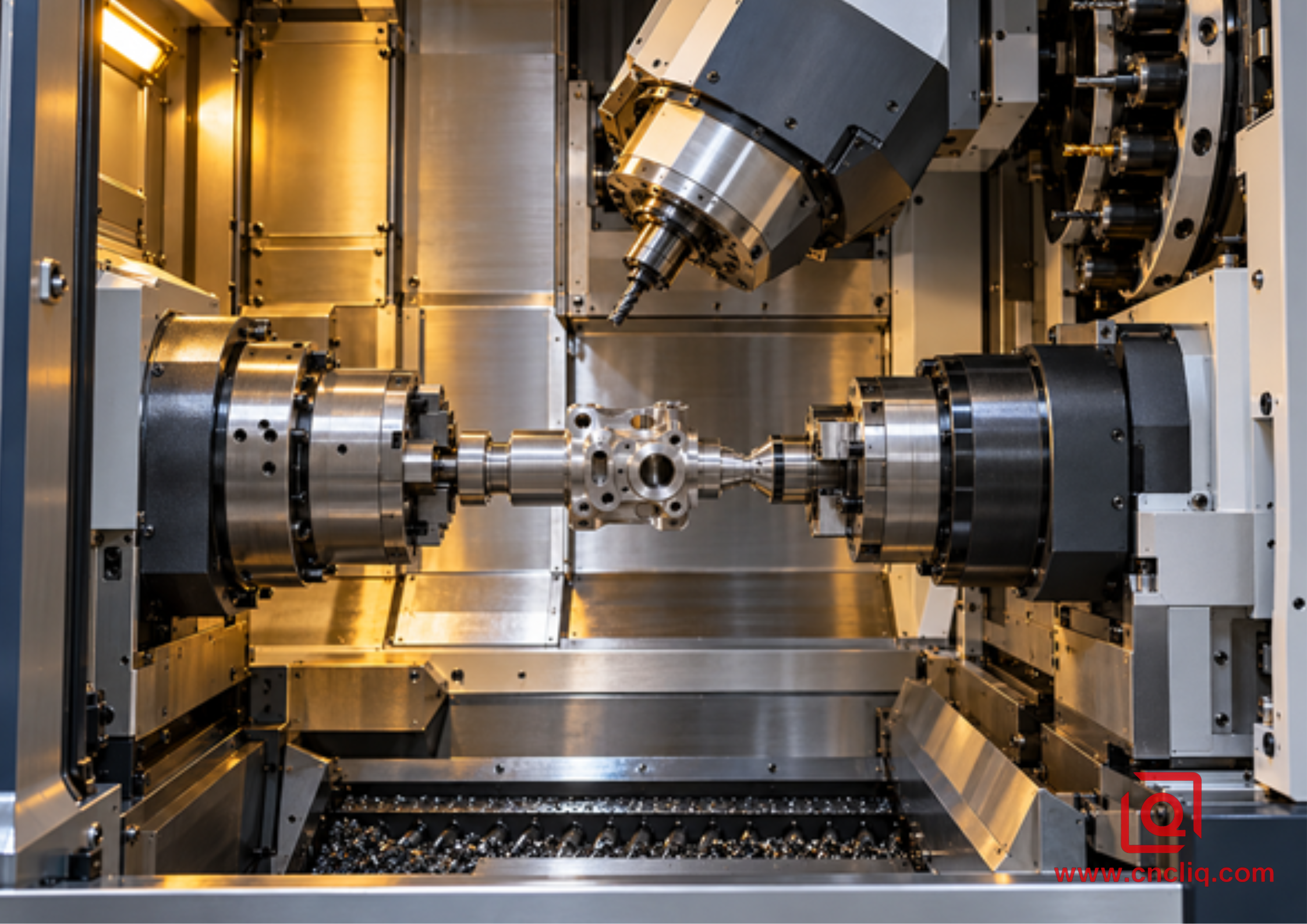
I keep the housing in a B-axis mill-turn and the bore, face, pocket and surrounding profile can share one machine coordinate system. If the rear side of the housing needs work a counter spindle can accept the housing under a programmed handoff. Transfer is not magic; grip force and pickup runout still need checking. The housing is, however easier to measure and repeat than a trip through the shop.
That is why "done in one" should not be sold as a blanket accuracy guarantee. Temperature, tool runout, chuck condition, stock stress, rotary-center calibration, and part stiffness remain very real. The narrower, more useful benefit is that several potential datum breaks have been removed.
For housings see our comparison of CNC turning and turn-mill routing. The comparison explains when a second fixture remains reasonable and when the relationship, to the turned axis deserves protection.
4. What Makes a Simultaneous Path Behave?
CAM shows a line. The machine doesn't see that line. It only gets coordinates, tool vectors, feed commands and rotary positions from a postprocessor. A tiny tip movement, close, to the center can require a shift in B or C. Near a singularity a surface that looks smooth can cause a reversal or a sudden speed change.
An experienced programmer watches the plot, not the simulation. Sometimes the fix is to angle the tool from the side. Sometimes the surface needs to be split into two parts. A short repositioning move can be safer than pushing one path through a zone.
Tool-center-point control keeps the programmed cutting point in position as the head tilts. It relies on a pivot value and a machine that is properly calibrated. If the tool length is wrong or the rotary calibration is outdated the edge can shift. That's why warm-up tool measurement and the machine builder's calibration routine should be part of every job plan. Especially when the profile spans a range of B-axis movement.
Tool shape makes a difference. A ball nose cutter is forgiving, though its center doesn't cut well. Barrel and lens cutters can finish surfaces with a larger effective radius. The CAM contact calculation and clearance model must be reliable. Flank milling with a bull-nose tool can be fast on a ruled wall. None of these tools works for every case. Surface shape, tool access, holder clearance, and the required finish all play a role.
5. A Prove-Out Routine That Respects the Machine
Mill-turn collisions cost a lot because the work zone is crowded. The chuck, jaws, counter spindle, B head, lower turret, tool holder and part can all occupy the space. Use a written prove-out checklist instead of trusting one green simulation screen.
1. Begin with the drawing datums. Decide which bore, journal, face or pilot controls the assembly before assigning operations.
2. Match the CAM model to the machine. Chuck style, jaw steps, tool holders, gauge lengths, spindle noses, and travel limits must be current.
3. Separate fixed-angle work from simultaneous work. The shortest program is not always the safest program.
4. Model the tool assembly. A cutter may clear while its collet nut or spindle housing does not.
5. Rough while the part remains stiff. Leave support near walls. Finish bores after interrupted cuts when the design permits.
6. Simulate the posted code. CAM verification checks the path; code simulation exposes rotary rewinds, post errors and travel-limit surprises.
7. Prove the deepest negative approach, the tightest chuck clearance, and every spindle-transfer state at controlled override.
8. Measure the part, from the drawing datums. Decide how the compound features will be reached before the machine starts cutting.
9. Freeze what worked: post version, jaw revision, tool list, offsets, inspection program and setup notes.
DMG MORI highlights look-ahead for smooth motion, while Okuma lists collision-avoidance functions on its multitasking controls. Both are safeguards. Neither can correct a machine model or an assembled tool.
6. Workholding, Reach, and the Chips Nobody Sees in CAM
Tilting the head often lets us use a short cutter instead of a long one. Less overhang usually means a steadier cut, a cleaner wall, and fewer problems with chatter. It does not fix workholding. A feature far, from the chuck can still behave like a lever after roughing has removed the surrounding stock.
The operation order should preserve support for as long as practical. Rough heavy sections first; keep rings or webs where the design permits. Avoid finishing a bore before an interrupted cut beside it. A counter spindle can receive the part. Its grip force must suit the wall thickness.
Then look at gravity. A pocket that empties at B0 may become a chip cup when the head is tilted. Recut chips can scar a seal land even though the dimensional report remains acceptable. Through-tool coolant, a nozzle, air blast and an occasional safe reorientation are fixes. The right combination changes with the alloy and enclosure.
Aluminum may build up on an edge. Move as residual stress is released. Austenitic stainless steel dislikes rubbing. Titanium keeps heat close, to the cutting edge. Those are reasons to plan engagement and chip evacuation, not reasons to rely on generic speed recommendations. Final cutting data must follow the material condition, cutter supplier, engagement, coolant delivery and machine rigidity.
7. Inspect the Relationship, Not Just the Dimensions
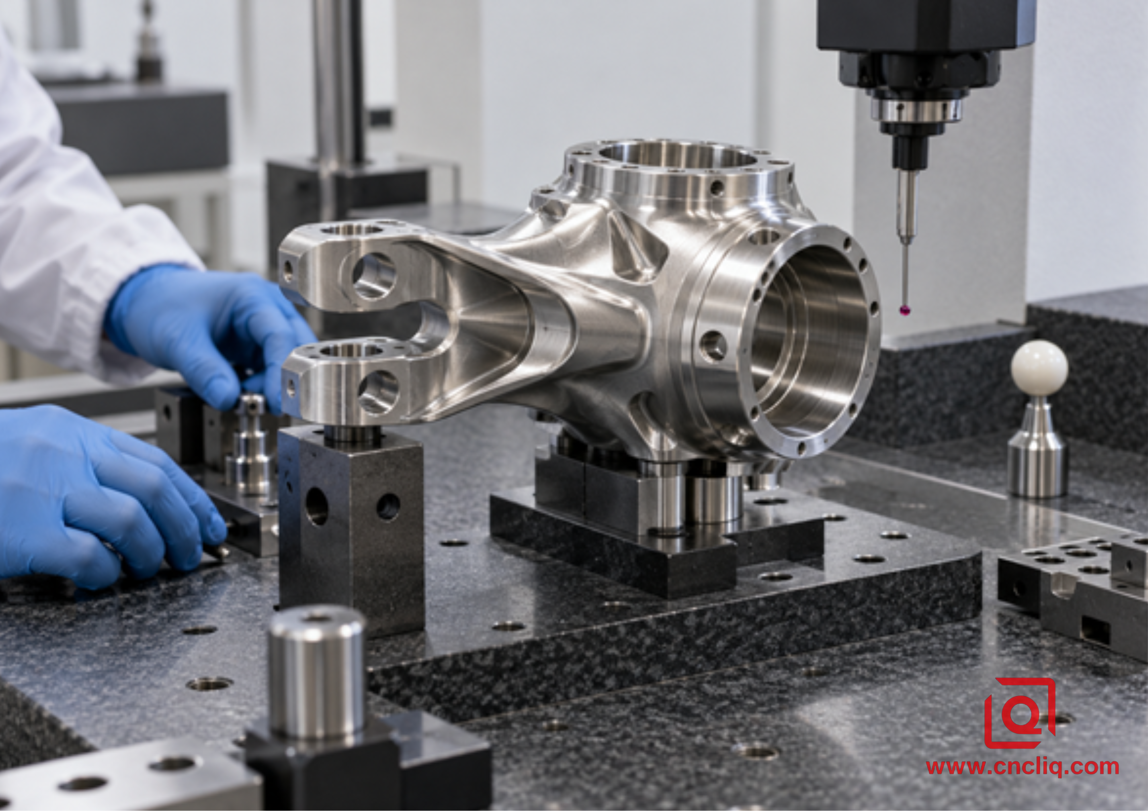
The inspection setup must match the drawing. Start by identifying the bore or journal axis. Then set the locating face. Only after these are established should you report the position of a port the shape of a pad or how a bolt pattern is clocked.
A CMM works well for many of these measurements long as the stylus can access the feature and the alignment is done right. For edges an optical system might be better. A dedicated gauge could give results for a production connector or a mating envelope. The method used matters; wo reports can show values not because the part changed. Because each one built the datum differently.
Rotary accuracy needs its check. The X, Y and Z readings may look fine. An incorrect B pivot can shift the tool tip during rotation. Always follow the machine builder's approved calibration procedure. If you're doing work it's wise to check accuracy after maintenance a crash, a big temperature change or any event that might have disturbed the head or the probing system.
8. Anonymized Composite Case: A Robotic Fluid-Control Housing
This example combines requirements that are common in machined housings. All customer-specific details have been removed. It is meant to illustrate a process not to represent any customer production order.
The component began as a blank. The bore and the front sealing face defined where the assembly would fit. Around that axis there were four ports, a tilted sensor pad and a curved relief that extended behind a flange. The drawing maintained control over the customer's material, tolerance and finish needs.
One way to approach the machining could be in stages. The first idea was to use a lathe a 3-axis mill with a fixture. The finished bore would then guide the milling operation. This method needed to protect the bore from clamping damage and ensure the fixture could repeat its position accurately. The wraparound relief required a ball nose tool or an alternate indexing setup.
The second approach kept the bore, face, ports, pad and relief all on a B-axis mill-turn machine. The ports and sensor pad were machined in three plus two positions. Only the relief used B and C motion with a cutter tilted away from the flange. A counter spindle then took care of the diameter on the face.
The interesting part was what the team decided not to do. The team did not convert the program to 5-axis machining. This choice kept the code straightforward and easier to verify. The virtual setup included the jaw steps, holder noses and the milling spindle housing. Inspection started at the bore then moved to the face and finally to the sensor pad. Fixtures and a shorter datum chain were key in making this decision.
Liqin's custom hydraulic manifold product page shows capabilities, in port machining, deburring, cleaning and inspection. Even a new machined housing still needs a path built around its approved model, drawing, volume and test plan.
9. When a B-Axis Is More Machine Than the Part Needs
I recommend the CNC lathe when the geometry that matters is rotational and can be reached with fixed tools.
I find the C/Y-axis live tooling useful for tasks such, as surfaces, slots, face holes, cross-holes and off-center threads.
I think the 3+2 B-axis positioning is best when faces or bores need to be machined at fixed angles.
I have seen the machining center become a choice when broad prismatic milling dominates the cycle time and turning work is minimal; two machines together can handle repeat production better.
I think the 5-axis mill-turn machining is optimal when geometry changes continuously and relates to the turned datum and when transferring between machines would add risk.
I always check the machine envelope before becoming excited about the number of axes. The chuck size, bar capacity, Y-axis travel, B-axis range, tool length, counter-spindle access and holder clearance can make certain setups impossible.
Examples of machine capabilities show that Okuma publishes a 240-degree B-axis swing and a 12,000 rpm milling spindle for the MULTUS U5000; DMG MORI publishes a plus or minus 120-degree B-axis range for the NT 4250 DCG. These numbers reflect what those manufacturers offer. These are not specifications for Liqin equipment. They are not guarantees, for any job.
10. What Should Be in the RFQ?
1. Include a 3D model and a 2D drawing that is controlled. The 3D model shows the surface. The 2D drawing shows the requirements.
2. Name the material grade and the condition. If other materials are allowed explain the approval process.
3. Show the datums and the three features that would stop assembly if they moved.
4. State prototype quantity, production lot size, annual demand, and the likely repeat schedule.
5. Describe the finish edge condition, cleanliness, heat treatment, coating, passivation, anodizing and masking where needed.
6. List the records you expect: material certificate, dimensional report, CMM output, traceability, or capability study.
7. Explain mating parts or inspection intent where a compound surface could be interpreted in more than one way.
8. Let engineering propose 3+2 for features that do not need simultaneous motion. This can lower programming cost without hurting the datum plan.
9. Ask the quote to list assumptions about tooling, fixtures, inspection, samples and production release.
Our CNC machining RFQ checklist covers the purchasing side in detail. If your files are ready send them through the contact page. Point out the bore, face, port or profile that has the assembly risk. The best answer could be live-tool turning, 3+2 B-axis work, full simultaneous mill-turn or a controlled split route.
FAQ
1. Is a B-axis lathe the same as a 5-axis machining center?
No. A B-axis mill-turn is organized around a turning spindle that rotates the work while a swiveling milling spindle approaches it. A typical 5-axis machining center holds the component, on a table. Uses a rotary head. Round parts that have important turned bores journals or faces often suit mill-turn; parts that are dominated by milling may suit the machining center.
2. Does every B-axis component require simultaneous motion?
No. Many jobs use the B head mainly for 3+2 positioning. The head. The C axis rotates the part and the linear axes do the cut. Continuous movement is worth the programming when the tool angle needs to change during cutting or when tilting the cutter is needed for access, contact or a better finish.
3. Can the machine truly finish a part in one setup?
It can often handle the front circumference angled details and sculpted surfaces without requiring manual reclamping. A counter spindle can pick up the part to work on the side. This transfer creates a holding condition. It is important to check the runout jaw force and how everything aligns with the datum before releasing the part, for production.
4. Which part families are good candidates?
Look first at parts built around a tubular, forged, or turned center: sensor housings with angled ports, robotic wrist bodies, medical instrument components, and fluid-control parts with blended passages. The case becomes stronger when a milled part is close, to the hole or surface made during turning.
5. What usually drives the quoted price?
Material, size, cutting time tool count, simultaneous-path complexity, holders, jaws, spindle transfer, prove-out, inspection access, finish, tolerance, post-processing, documentation and volume all matter. A longer cycle can still cost overall when it removes fixtures, queue time, handling and rework. Compare the route, not the machine rate.
Summary
A B-axis mill-turn machine is helpful when you have to work with turned datums and milled shapes in the process. Use tooling, for features that don't need movement. Use 3+2 axis machining when you are dealing with fixed angles and need to place the tool at angles. Only use motion when the cutting tool needs to change direction times during the operation. To make this ability function properly you need tools, machine simulation, careful part transfer, correct rotary calibration and inspection based on datums. A full RFQ gives the supplier a reason to choose a setup, not just because 5-axis sounds better.
Contact Information
Company: Ningbo Liqin Industry Co., Ltd.
Daily customer maintenance & after-sales support: service@shturl. zhuwanying@cncliq.com
New inquiry, quotation & order discussion: business@shturl. zhouli@chinaliqin.com
Hotline: +86 18757148656
Disclaimer
All technical articles, material specifications, machining recommendations, and surface treatment details published on this blog are for informational and reference purposes only. Please note that general blog insights do not replace signed technical agreements. Because custom parts vary by material heat numbers, machine calibrations, and specific tolerances, binding quality specs are governed solely by your approved CAD drawings, signed contracts, and formal quality plans.
All customer case studies featured on this blog have been thoroughly anonymized and sanitized. The performance metrics, manufacturing workflows, and imagery displayed serve solely to demonstrate our custom machining capabilities and do not represent a single universal standard for all orders.
Liqin Manufacturing Team
Built on 18 years of precision engineering experience, Ningbo Liqin Industry manufactures high-tolerance metal components for demanding global markets. We operate out of a 6,500 m² production hub equipped with over 150 machines, running 4-axis and 5-axis CNC machining, mill-turn machining, cold extrusion, and pressure die casting under one roof. This setup allows us to manage projects seamlessly, taking parts from initial CAD concepts directly to finalized shipments.
We handle quality control with zero compromise. We treat tight tolerances with the engineering discipline they require. Backed by ISO 9001, ISO 13485, and IATF 16949 certifications, our QA engineers run strict IPQC, FQC, and OQC checks on every single production batch. From CMM dimensional mapping and optical profiling to hardness and salt-spray testing, we validate your critical specs upfront-so you receive drop-in ready components with zero assembly headaches or costly line stoppages. On top of manufacturing, you can rely on us for two-hour response times on new RFQs, direct support for prototype sampling, and smooth export shipping across Europe, North America, Asia, and Oceania.
Welcome your inquiries and samples. Visit our website or contact us directly for a competitive quote!
