 English




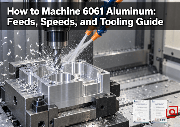
Most shops find 6061 friendly—until it suddenly is not. Chips can choke a deep pocket. A tall wall may start ringing. Sometimes a bright wall turns gray in one pass because the cutter has picked up a skin of aluminum. Fast metal removal is the easy part. Repeatable work needs a keen edge, a chip with some body to it, somewhere for that chip to go, and a fixture that holds without squeezing the component out of shape.
Who is this for? Anyone who has to design, buy, quote, or cut a 6061 part and wants more than a chart copied from another machine. We will build a first setting, read what the cut is telling us, and collect the details a supplier needs for a useful quote. Keep one rule close: every number in this article is a place to begin a trial. The cutter maker's sheet comes first, followed by the real limits of the spindle, holder, overhang, coolant, fixture, CAM path, and material lot.
Quick answer: If this job had just reached the machine, a polished two- or three-flute carbide cutter would be the first tool worth trying. The air or coolant has to hit the exit side of the cut; spraying the holder does little. For surface speed, 300 m/min sits in cautious territory. It is a trial point, nothing more. Pick chip load for the tool diameter and setup, do the feed calculation with the RPM the spindle will truly run, and test a short stretch. Hear a rubbing squeal? Slowing the feed can make it worse. Look at the edge and the chip before touching the override.
Why 6061-T6 Cuts Well—and Why Shops Still Scrap It
Magnesium and silicon give 6061 its heat-treatable character. A T6 callout means solution heat treatment followed by artificial aging. T651 and T6511 add stress-relief steps suited to the way the stock was made. Those suffixes are not decoration; they can change how the blank behaves when one side is opened up. For purchasing, do not stop at “6061.” State the temper and stock form on the drawing and request traceable material documentation when the application requires it. ASTM B221, for example, covers aluminum and aluminum-alloy extruded bars, rods, wire, profiles, and tubes. Plate and sheet use different specifications.
On the machine, 6061 usually produces lower cutting forces than steel and allows high surface speed. Its thermal conductivity helps move heat, yet the material can still smear across a dull edge. That smear becomes built-up edge, or BUE. Once BUE changes the cutter geometry, size and finish can shift in a few passes. Deep pockets add another problem: chips leave the tool, bounce around, and get cut again. A recut chip is hard on the surface and unpredictable at the edge.
Residual stress matters too. Remove most of the stock from one side of a plate and the part may move when the clamps release. A faster program is not useful if the free-state component is no longer flat. For thin walls, large pockets, or tight datum relationships, plan roughing, unclamping or restaging, and a separate finishing step. Our broader guide to aluminum machining processes compares milling, turning, and extrusion routes when billet machining is not the only option.
Start With the Three Numbers That Actually Control the Cut
RPM on its own is a lousy shop instruction. Twelve thousand revolutions per minute might throw a clean chip or polish the wall by friction. Cutter diameter, tooth count, and forward feed decide which one you get. Work from surface speed and feed per tooth. The standard metric relationships published in Sandvik Coromant's milling formulas are:
Need spindle speed? n = (Vc × 1000) ÷ (π × D).
Need table feed? Vf = fz × n × z.
Checking removal rate? Q = (ap × ae × Vf) ÷ 1000.
The notation is less mysterious than it looks. Vc? Surface speed, in m/min. D is cutter diameter at the cut. The little fz is the chip given to one tooth, while z counts the teeth doing work. Down the tool is ap; across the tool is ae. The math will happily accept a loose vise or 60 mm of unnecessary overhang. The machine will not. Use the equations to keep the arithmetic straight, then judge whether the setup deserves those numbers.
A worked 10 mm end-mill example
Put a 10 mm, three-flute carbide end mill into the calculation. A Vc of 300 m/min puts the spindle near 9,550 rpm—close enough for choosing a machine setting, but not a reason to ignore the spindle's own limits. Give each tooth 0.08 mm and table feed lands near 2,290 mm/min. With 3 mm axial depth and 3 mm radial engagement, the calculated removal rate is about 20.6 cm³/min. On a rigid side cut, with the right aluminum cutter and a clear chip stream, that is worth a short trial. Full-width slotting is another job; do not carry the numbers across unchanged.
|
Tool and operation |
Conservative proof-cut input |
Calculated result |
Shop-floor note |
|
Ø6 mm carbide; z = 2; side cut |
Vc 300; fz 0.04 |
n 15,915; Vf 1,273 |
Long overhang or a soft fixture? Back off and check available torque. |
|
Ø10 mm carbide; z = 3; rough side cut |
Vc 300; fz 0.08 |
n 9,549; Vf 2,292 |
There is room for the chip, and the setup must be rigid. |
|
Ø12 mm carbide; z = 3; rough side cut |
Vc 300; fz 0.10 |
n 7,958; Vf 2,387 |
Power, holder balance, sideways bite, and clamp load all get a vote. |
|
Ø10 mm carbide; z = 3; finish pass |
Vc 400; fz 0.04 |
n 12,732; Vf 1,528 |
Leave even stock. The edge still needs a chip; do not let it skate. |
Calculated training examples only. They do not replace the cutter manufacturer's chart or a controlled first-off trial.
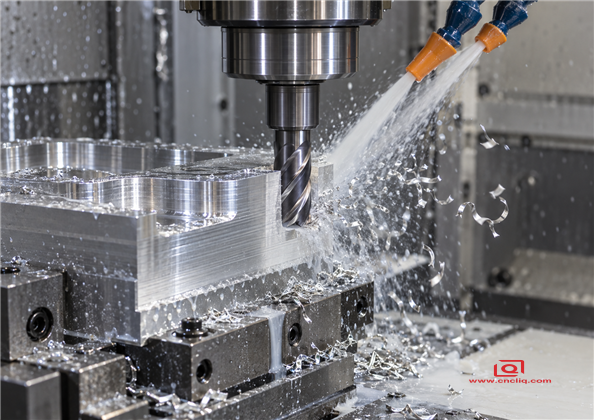
Constant engagement and a clear chip path matter as much as programmed RPM.
Picking a Cutter That Will Not Pack Up With Aluminum
Flute count: make room for the chip
Two flutes buy breathing room. That is useful in a slot, on a light machine, or anywhere chips are the first worry. Three flutes trade a little of that space for another cutting edge, which is why the format shows up so often in production profiling and adaptive roughing. Four flutes can work in stable, open cuts, but they leave less room for a bulky aluminum chip. Do not choose flute count by habit from steel jobs.
Edge and flute geometry
Look for a sharp positive rake, a high helix, polished flutes, and enough core strength for the tool diameter. Polished uncoated carbide is a reliable baseline. ZrN or DLC options may help in some applications, but only use a coating supported by the tool maker for aluminum. A thick aluminum-containing coating selected for steel can encourage adhesion. Tool manufacturers such as Harvey Tool publish aluminum-specific high-helix designs and describe posted feeds and speeds as suggested starting values.
Keep the assembly short and true
Tool stickout is leverage. Every unnecessary millimeter makes deflection and chatter easier. Keep gauge length only as long as access demands. Clean the collet, use a hydraulic or shrink-fit holder where the job warrants it, and check runout out near the edge—where the error matters. A premium cutter in a dirty, worn holder will still leave stripes down the wall. For a critical bore or sealing face, separate roughing and finishing tools if tool life or size control justifies it.
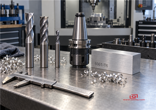
Select flute count, edge geometry, and holder as one system.
Operation-by-Operation Adjustments
|
Operation |
Preferred approach |
What usually goes wrong |
First correction |
|
Adaptive or side roughing |
3-flute polished carbide; constant radial engagement; climb milling |
Load spikes at corners, chatter, chip recutting |
Smooth entry and corner motion; reduce radial engagement before starving chip load |
|
Full-width slotting |
2-flute or open 3-flute tool; modest stepdown; direct evacuation |
Packed chips and welded edge |
Reduce feed roughly 30–50% from the proven side-milling value, then inspect chip flow |
|
Finishing walls |
Sharp dedicated edge; even stock; continuous pass where practical |
Vertical lines, taper, corner dwell marks |
Check runout, deflection, actual feed in short moves, and allowance consistency |
|
Thin floors and ribs |
Balanced removal; light finishing pressure; support near cut |
Wall push-off, vibration, free-state distortion |
Change toolpath and support strategy before chasing the error with offsets |
|
Drilling |
Sharp non-ferrous drill; reliable peck and chip exit plan |
Chip packing, oversize entry, burrs |
Shorten peck as depth grows, improve coolant direction, verify point condition |
|
Threads |
Choose cut tap, form tap, or thread mill from depth, size, volume, and risk |
Galling, packed blind holes, breakage |
Check pre-hole, lubrication, chip space, and post-finish dimension |
Slotting is a different job
A side cut leaves an open direction for chips. A slot traps the cutter between two walls. Engagement rises, coolant struggles to reach the edge, and a chip can be pulled back into the cut. That is why copying an aggressive adaptive-milling feed into a full slot so often ends badly. Begin with a smaller axial step, lower feed than the proven side cut, and a tool with open flutes. Never dwell at the bottom.
Finishing needs stable pressure, not a “whisper cut”
An extremely light finish allowance sounds safe, but the edge may rub over runout highs instead of cutting continuously. Leave a consistent allowance the chosen tool can shear. Use a smooth lead-in and lead-out away from the critical face. On tall walls, consider staged depths or a relieved-neck tool. If the wall tapers, measure it before editing compensation; the real cause may be deflection, not an incorrect tool diameter.
Coolant, Air, and Chip Control
In 6061 machining, chip evacuation is the first cooling system. Flood coolant can lubricate and carry heat, but a large volume pointed past the cutter does not clear a blind pocket. Aim the stream where the flute exits the work. Through-tool coolant is valuable for deep features when the tool supports it. A forceful air blast or minimum-quantity lubrication can also work on suitable jobs, provided chips leave the enclosure safely and the process meets plant rules.
Read the chip bin. Bright, separate curls and a steady sound suggest that the edge is shearing. Powdery chips, squealing, or a gray smeared finish often indicate rubbing. Long nests around the holder point to poor breaking or evacuation. Aluminum welded to the edge means the process has already changed. Stop, clean or replace the tool, and correct the cause; an offset tweak will not restore the original geometry.
Fixturing, Heat, and Dimensional Stability
A vise can bend a compliant part into tolerance for inspection on the machine. Release it and the error appears. Use enough grip to resist cutting force, but do not treat clamp pressure as free stiffness. For thin-wall housings, support stock near the active cut, rough opposing areas in a balanced order, and reserve material for a separate finish setup. Probe results should be interpreted with part temperature in mind. Aluminum expands noticeably with temperature, so a warm part and a stable inspection room can disagree even when both measurements are repeatable.
When geometry spans several faces, fewer reclamps can protect position and runout. Our guide to multi-axis CNC milling for complex aluminum geometry explains where a 4- or 5-axis setup adds real value. It is not automatically the cheapest answer. A simple prismatic bracket may be better on a well-planned 3-axis fixture. Ask which setup protects the critical datums with the least accumulated error.
Troubleshooting 6061: Change One Variable at a Time
|
Symptom |
Likely causes |
Practical response |
|
Aluminum welded to flutes |
Dull edge, rubbing chip load, weak evacuation, wrong coating, recutting |
Replace or clean tool; restore chip load; improve aim; reduce engagement if the pocket cannot clear |
|
Chatter on straight walls |
Long stickout, flexible wall, weak holder, unstable engagement |
Shorten assembly; support wall; use constant engagement; adjust speed after checking mechanics |
|
Good open-cut finish, poor corners |
Machine deceleration, sudden engagement, toolpath dwell |
Add corner smoothing and check actual feed, not only commanded feed |
|
Part bows after unclamping |
Unbalanced removal, residual stress, excessive clamp force |
Rough both sides, release and restage, then finish from stable datums |
|
Burrs at exits and edges |
Dull tool, unsupported exit, poor operation order |
Support exit, tune breakthrough feed, add controlled chamfer and documented deburr |
|
Size drifts through batch |
BUE, wear, thermal change, chips under locating surfaces |
Inspect edge and fixture; track temperature and offsets; clean datums at set intervals |
Verified Product Example: 6061-T6 Lightning-Arrester Housing
A useful site-verified example is Liqin's 4G signal-station lightning-arrester housing. The published route uses 6061-T6 aluminum, cold extrusion, stress-relief treatment after forming, and CNC finish machining. That combination illustrates an important cost lesson: not every production part should be hogged from a rectangular billet.
The formed blank establishes much of the shell contour and cavity before cutting.After forming, milling picks up the datum faces and completes the slots, grooves, bores, counterbores, and threads. The job has changed by then. Hogging is no longer the prize; repeatable location, released stress, and clean finishing beside near-net surfaces are. This hybrid route is worth studying when volume and geometry support dedicated tooling. For prototypes or frequently changing designs, billet machining may remain practical. The answer depends on drawing maturity, annual volume, tolerance distribution, and tooling payback.
Anonymized Shop Case: 6061 Sensor Housing With Mixed Requirements
In a previously published and anonymized case, an automation customer required a 6061-T6 housing for LiDAR equipment used around port cranes. The component combined two H7 bearing journals, an internal mounting shelf needing metal-to-metal thermal and electrical contact, and an O-ring gland at the lens face. The external body also needed corrosion and handling protection. Those requirements conflicted: coating the whole part protected the outside but risked changing bearing fit and insulating the grounding area.
The published flow used 5-axis machining and planned the bearing bores around the downstream finishing sequence instead of treating anodizing as an afterthought. The lesson applies directly to feeds and speeds. A stable roughing recipe is only half the process. Finish allowance, bore tool, part temperature, inspection stage, masking plan, and coating growth must all point to the final assembly dimension. Review the source case in the guide to finishing CNC-milled aluminum parts.
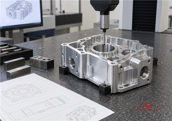
Inspection closes the loop between programmed parameters, free-state geometry, and assembly requirements.
What to Send for a Fast, Useful 6061 Machining Quote
A supplier cannot price process risk from a screenshot. Send a native STEP file and a controlled 2D drawing. Identify alloy and temper, critical datums, real tolerance zones, surface finish only where it matters, thread standards, cosmetic faces, and whether dimensions apply before or after anodizing. Add expected order quantities and the prototype-to-production plan. If mating parts exist, share relevant interface dimensions or stack-up.
· Material: 6061-T6, T651, or T6511 as appropriate, plus certification requirements.
· Geometry: STEP model and revision-controlled PDF drawing.
· Critical features: datums, fits, true position, sealing faces, thread class, and inspection method.
· Finish: as-machined, bead blast, chem film, anodize, hardcoat, masking, color, and thickness.
· Commercial scope: prototype quantity, annual usage, batch size, delivery, destination, packaging, and documents.
Do not assign the tightest tolerance to every dimension. It adds finishing passes, inspection time, and scrap exposure without improving function. The article on CNC tolerance and cost shows why functional tolerancing is a purchasing decision. For deep pockets, thin walls, awkward access, or multiple coated fits, request DFM feedback before releasing production. Our aluminum machining cost guide covers further choices that reduce spindle time without weakening the part.
Need a second set of eyes on your 6061 part? Send the STEP file, 2D drawing, quantity, finish, and destination. Liqin's engineering team can review tool access, thin-wall risk, datum strategy, and post-finish tolerances before quotation. When the RFQ closes the obvious gaps, buyer and supplier can argue about the real cost drivers instead of paying an uncertainty tax.
FAQs
1. What is the best end mill for CNC milling 6061 aluminum?
Start with an aluminum-specific carbide tool that feels sharp, has polished flutes, and carries positive rake. Two flutes leave more chip room for a slot or a modest machine. Three usually earn their keep in side cuts and adaptive roughing. Keep the tool tucked in, check runout at the edge, and open the maker's data sheet. “Carbide” alone tells you almost nothing about flute shape or coating.
2. What feeds and speeds should I use for 6061-T6?
Begin from cutting speed and chip load, then calculate RPM and table feed. For carbide side milling, 300 m/min is a cautious reference from which to do the calculation; chip load still belongs to the cutter diameter and the stiffness in front of you. The examples above show the arithmetic. A slot, a long-reach tool, a thin wall, a soft fixture, or a spindle short on power changes the bargain. Prove a short cut, inspect chips and load, then change one variable at a time.
3. Why does 6061 aluminum stick to my cutter?
Built-up edge usually appears when the tool rubs or chips cannot escape. Common causes are a dull edge, feed per tooth too low for actual RPM, unsuitable coating, poor coolant or air direction, excessive engagement, and chip recutting inside a pocket. Stop and inspect the cutter first. Once aluminum is welded to the flute, effective geometry has changed and compensating with an offset will not create a stable process.
4. Can 6061 parts hold tight tolerances after anodizing?
Yes, but the drawing and process plan must account for surface preparation, anodic growth, masking, temperature, and inspection stage. State whether dimensions apply before or after finishing and identify bearing bores, threads, grounding pads, and sealing faces needing special control. Review Liqin's anodizing tolerance guide before freezing a coated fit.
5. What should I ask a 6061 CNC machining supplier before ordering?
Ask the supplier to walk the job from stock rack to inspection bench. Which temper will arrive? Where do chips leave a deep pocket? How will a thin wall be supported? When is the part released between roughing and finishing? Which datums are checked, and at what stage does coating enter the dimension plan? Request the inspection documents your application needs and clarify revision control, packaging, and nonconformance communication. A practical supplier should explain the process in relation to your drawing, not promise one tolerance or feed rate for every part; this aluminum OEM quality guide provides a fuller checklist.
Summary
The winning 6061 program is rarely the one with the biggest RPM number on the setup sheet. Give a sharp aluminum cutter a real chip. Keep yesterday's chips out of today's cut. Match the sideways bite to the spindle and fixture, then finish from datums that stay put after release. Coating and inspection belong in that plan from the start. Trial the chart, write down what the actual machine accepts, and send CAD, drawing, quantity, and finish together when it is time to quote.
Contact Information
Company: Ningbo Liqin Industry Co., Ltd.
Daily customer maintenance & after-sales support:service@shturl. zhuwanying@cncliq.com
New inquiry, quotation & order discussion:business@shturl. zhouli@chinaliqin.com
Hotline: +86 18757148656
Disclaimer
All technical articles, material specifications, machining recommendations, and surface treatment details published on this blog are for informational and reference purposes only. Please note that general blog insights do not replace signed technical agreements. Because custom parts vary by material heat numbers, machine calibrations, and specific tolerances, binding quality specs are governed solely by your approved CAD drawings, signed contracts, and formal quality plans.
All customer case studies featured on this blog have been thoroughly anonymized and sanitized. The performance metrics, manufacturing workflows, and imagery displayed serve solely to demonstrate our custom machining capabilities and do not represent a single universal standard for all orders.
Liqin Manufacturing Team
Built on 18 years of precision engineering experience, Ningbo Liqin Industry manufactures high-tolerance metal components for demanding global markets. We operate out of a 6,500 m² production hub equipped with over 150 machines, running 4-axis and 5-axis CNC machining, mill-turn machining, cold extrusion, and pressure die casting under one roof. This setup allows us to manage projects seamlessly, taking parts from initial CAD concepts directly to finalized shipments.
We handle quality control with zero compromise. We treat tight tolerances with the engineering discipline they require. Backed by ISO 9001, ISO 13485, and IATF 16949 certifications, our QA engineers run strict IPQC, FQC, and OQC checks on every single production batch. From CMM dimensional mapping and optical profiling to hardness and salt-spray testing, we validate your critical specs upfront—so you receive drop-in ready components with zero assembly headaches or costly line stoppages. On top of manufacturing, you can rely on us for two-hour response times on new RFQs, direct support for prototype sampling, and smooth export shipping across Europe, North America, Asia, and Oceania.
Welcome your inquiries and samples. Visit our website or contact us directly for a competitive quote!
