 English




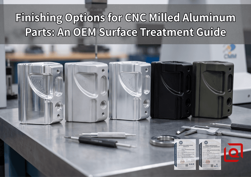
Fresh out of the machining vise, a contoured 5-axis finish looks immaculate. Those vivid diffraction patterns running along sculpted 6061-T6 stock confirm zero spindle runout, dialed-in CAM feeds, and an endmill slicing through aluminum without chatter.
Then that bare part hits the assembly bench—and real problems kick in.
Bare 6061 is soft, chemically active, and a magnet for scuffs. Drop an unprotected piece on a damp table overnight, or grab it with bare, sweaty palms, and chalky white corrosion patches pop up by morning. Drive a plain stainless bolt straight into a dry blind tap, and the threads will seize rock-solid long before that screw ever hits spec torque.
Machining defines the geometry, but the finishing line transforms that raw geometry into an operational product. Too often, design prints arrive on our desks with a hasty, generic callout like "Black Anodize" placed casually in the title block. Doing this without planning for material growth, electrical conductivity, or masking boundaries turns assembly into a gamble.
Below is an engineer’s field guide to post-processing CNC-milled aluminum parts—focusing on practical trade-offs, dimensional nuances, and production steps that bridge the gap between digital CAD models and reliable physical hardware.
Engineering Comparison: Common Finishes for Milled Aluminum
| Finish Type | Primary Specification | Typical Dimensional Shift | Finished Surface Feel | Primary Engineering Purpose |
| As-Machined | ISO 2768-m / ISO 1302 | Baseline nominal (Zero change) | Smooth with visible micro-toolpaths | Functional prototypes, internal brackets, quick fit-checks. |
| Bead Blasting | Media-specific (#8 to #12 glass) | Slight edge softening (Micro-erosion) | Velvet-like, soft satin texture | Removing cutter lines, eliminating glare, pre-anodize prep. |
| Type II Anodizing | MIL-A-8625 Type II | Modest outward growth (~0.008 mm/side) | Smooth, hard, uniform sheen | Electronics enclosures, cosmetic housings, standard brackets. |
| Type III Hardcoat | MIL-A-8625 Type III | Heavy buildup (~0.025 mm/side) | Matte, dense, highly scratch-resistant | High-friction sliders, hydraulic bodies, extreme wear surfaces. |
| Chem-Film (Alodine) | MIL-DTL-5541 Type II | Essentially zero change | Retains raw metallic feel | RF/EMI grounding faces, internal cavities, powder-coat primers. |
| Electroless Nickel | ASTM B733 / AMS 2404 | Uniform deposit (~0.015 mm/side) | Slick, hard metallic gloss | Deep blind bores, manifolds, harsh chemical environments. |
Step 0: The Baseline — Reading the As-Machined Surface
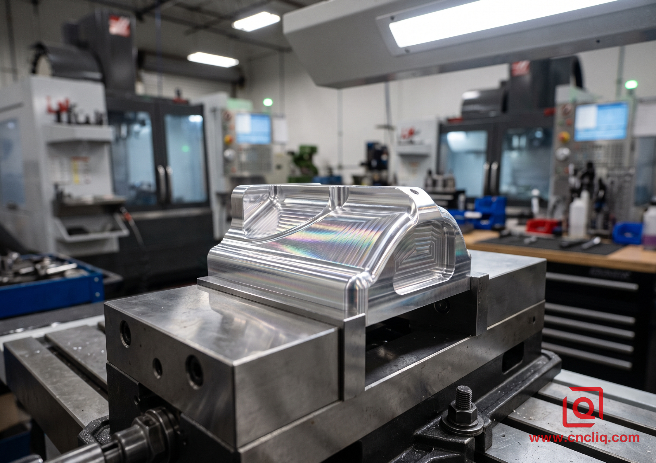
Every surface treatment interacts directly with the microscopic topology left behind by the cutting tool. You cannot simply cover up poor machining practices with a chemical dip.
       [ Single-Point Fly Cutter ]            [ Standard Ball Endmill ]
       ~~~~~~~~~~~~~~~~~~~~~~~~~~~            /\/\/\/\/\/\/\/\/\/\/\/\
       Flat, mirror-like lay                  Scalloped ridges & micro-cusps
       (Low friction, needs no blast)        (Requires blasting to blend lines)
When an aluminum housing exits the mill, its faces reflect the specific cutter path used.An 80 mm shell mill running light wiper passes creates a smooth, reflective face where tool engagement lines are barely perceptible to the fingertip. In contrast, deep interior pockets cleared with smaller endmills often display visible cutter scallops and subtle stepover marks.
Raw, as-machined parts work fine for hidden internal skeletons or test jigs that stay bone-dry. But skip the coating on copper- or zinc-heavy stock like 2024 and 7075, and they will corrode fast outdoors or around salt air. Even trusty 6061 takes a hit—leave traces of water-soluble coolant on it after pulling it off the table, and pitting starts setting in fast.
Bead Blasting: Creating the Uniform Satin Canvas
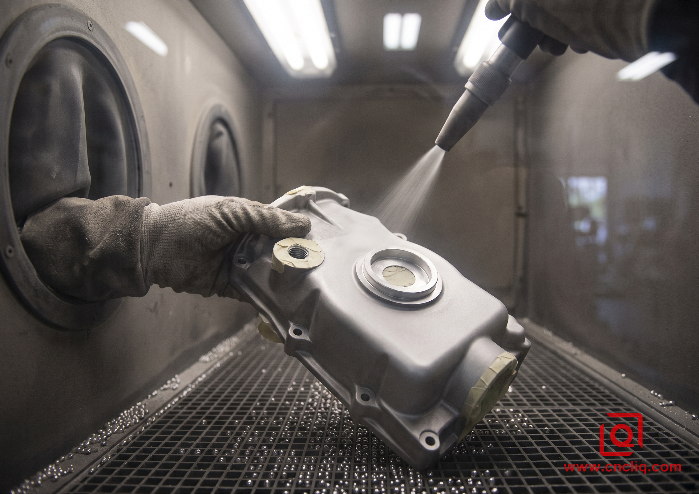
When you need an enclosure with a clean, diffuse appearance that hides subtle tool marks, bead blasting is the standard preparation step before chemical finishing.
The Physical Impact:
Compressed Air + Spherical Glass Beads ===> Peens surface & collapses cutter ridges
                                      ===> Leaves shallow micro-dimples (Matte look)
Spherical glass media will not bite into aluminum; think of the blast as millions of tiny peening hammers.Dry shop air drives the beads inside the cabinet, flattening feather burrs and blending stepped cutter paths across every face. The part comes out with a dull, uniform matte sheen that cuts down harsh overhead glare.
Shop Floor Practice:
Blasting takes off metal whether you want it to or not. Heavy-handed grit work washes out knife-edge geometry, rounds tiny chamfers, and jams fine media straight down into blind tapped holes. Got tight dowel bores or shallow pitch threads? Mask them off first, or at least keep the nozzle pointed away from those critical spots.
Type II Anodizing: Balancing Everyday Protection with Color
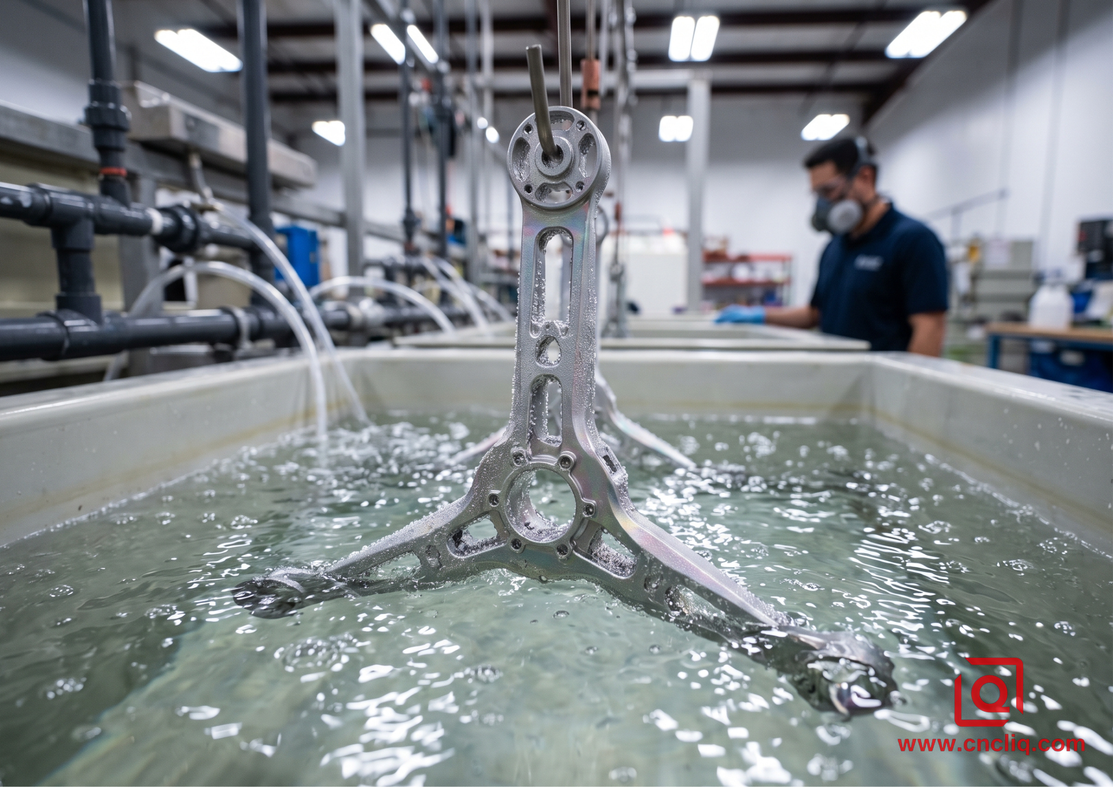
Sulfuric anodizing remains the default surface spec for CNC-cut gadgets, UAV arms, and test gear housings. Paint, powder coats, or plating just wrap around raw metal like a loose coat. Anodizing does not work that way. Run current through an acid tank, and the base aluminum itself turns directly into a tough, bonded skin of aluminum oxide.
The 50/50 Growth Dynamic:
+--------------------------+
| Outer Build: +50% of film | <--- Expands outward into space (Increases OD / Closes ID)
+==========================+ <--- Original Part Boundary
| Penetration: -50% of film| <--- Consumes the raw aluminum base
+--------------------------+
Because half of this ceramic-like film builds outward and half penetrates into the substrate,every anodized surface shifts slightly in space. If a finish specification produces an overall oxide layer of 0.016 mm:
-
External bosses and overall thicknesses grow by approximately 0.008 mm per side.
-
An internal reamed bore will shrink by roughly 0.008 mm on its radius, tightening the total diameter by 0.016 mm.
If an engineer designs a bore to accept a press-fit ball bearing with tight clearances and neglects to account for this layer, the bearing will bind during assembly. A knowledgeable CNC programmer compensates for this upfront by boring the hole slightly oversized during the finish pass, allowing the chemical tank to close the dimension back to true nominal.
Dyeing and the Hydration Seal
The newly formed oxide layer resembles an array of vertical, microscopic honeycomb pores. In Class 2 anodizing, these empty pores soak up organic dyes—deep blacks, clear silvers, rich blues, and golds.
Right after dyeing, the workpiece plunges into near-boiling DI water. That thermal shock hydrates the fresh oxide, puffing micro-pore walls shut so colorants stay trapped inside. Cut corners on this seal, and the open pores drink up coolant sludge or grubby fingerprints like a dry rag the second anyone touches it.
Type III Hardcoat Anodizing: Armor for Severe Wear
When an aluminum component needs to survive constant mechanical sliding, abrasive dust, or pressurized hydraulic fluids, standard Type II anodizing wears through too quickly. The job demands Type III Hardcoat.
Process Differences:
* Type II: Room temperature bath (~20°C), moderate current, decorative colors.
* Type III: Near-freezing bath (~4°C), intense current density, dense structural oxide.
Chilling the tank keeps hot acid from eating the fresh film away while heavy amperage forces oxidation deep down into the stock. What you get is glass-hard armor—scratch resistance rivaling carburized tool steel, without losing an ounce of aluminum’s weight edge.
Because hardcoat builds up much thicker than cosmetic anodizing, the outward growth on each face is noticeable. A typical 0.050 mm hardcoat layer pushes each external surface out by 0.025 mm. Sliding dovetails, dynamic piston shafts, and precision mounting shoulders will bind unless your CAD model leaves sufficient clearance for this thick skin.
Visual characteristics:
Natural, undyed hardcoat varies widely depending on the alloy underneath. On standard 6061, it settles into a handsome, deep charcoal or olive tone. On 7075, the zinc content lends it a bronze-green cast.If your project demands a consistent visual appearance across multiple mated components, machine them all from the same raw material lot.
Chemical Film (Alodine): Retaining Grounding and Tight Dimensions
Sometimes you need to protect aluminum from corrosion, but the part cannot tolerate any dimensional growth or loss of electrical conductivity. This is where chemical conversion coatings (commonly called Chem-Film or Alodine) excel.
 [ Anodic Oxide Film ] [ Chemical Conversion Film
              * Ceramic-like, non-conductive * Extremely thin,gel-like reaction
              * Noticeable dimensional growth       * Zero measurable dimensional shift
              * Ideal for friction and wear         * Maintains electrical ground paths
Skip the tanks and current of anodizing; chem-film builds its micro-thin shield just through a quick dunk.Coating buildup reads as absolute zero. That means you can wash it over RF waveguide flanges, micro-pitch threads, and tight reamed pin holes without trashing your slip fits down the line.
Because this conversion layer allows electrons to pass through freely, it is standard practice to specify chem-film inside electronic enclosures that require grounding continuity for circuit boards and internal shields.
Electroless Nickel Plating: Reaching Deep Internal Features
Anodizing relies heavily on line-of-sight electrical current.High currents tend to concentrate along sharp external edges, occasionally causing localized burning, while deep interior corners and the bottoms of narrow pockets receive very little current, resulting in a thin or non-existent protective layer.
Current Flow vs. Chemical Immersion:
Anodizing (Electric Field):   Heavy buildup on outer corners; weak inside deep cavities.Electroless Nickel (Liquid):  Flows everywhere wet; creates perfectly identical wall thicknesses.
Electroless nickel plating solves this problem through an autocatalytic chemical reaction. No electric current is passed through the tank. As long as the chemical bath can flow into a cavity and wet the metal, the nickel-phosphorus alloy deposits itself at a steady, uniform rate everywhere.
Deep hydraulic ports, intersecting internal channels, and recessed threads receive the exact same plating thickness as the exterior face, providing an even, durable, and corrosion-resistant metallic shield.
Strategic Masking: Protecting Critical Geometry
Complex custom parts rarely receive a single, uniform finish across every square millimeter. More often, you want a rugged hardcoat on the outer frame to resist scuffs, an unanodized, conductive grounding face on an interior boss, and raw, bare metal inside a precision dowel pin hole.
Achieving this requires deliberate masking before the part enters the chemical line.
 +----------------------------+
                      |   Type III Hardcoat Outer |
                      |  ========================= |
                      |  [ 6061-T6 Aluminum Body ] |
                      |                             |
                      |   ( ) Reamed Dowel Hole |
                      |   |   (Silicone Plug) |
                      |   |      [ MASKED ] |
                      +---+-------------------------+
Essential Masking Tools:
* Tapered Silicone Plugs: Hand-pressed into threaded blind holes and reamed dowel bores to seal out processing fluids.
* High-Temperature Tape: Neatly applied across flat mating pads to preserve bare aluminum for electrical grounding.
* Peelable Liquid Resist: Hand-painted onto irregular steps, curved boundaries, and intricate internal transitions.
Designing for Clean Breaks:
Capillary pull drags tank chemistry into microscopic cracks. Have someone tape off a boundary dead center on a flat, open face, and acid inevitably bleeds beneath the border, kicking back a ragged, bleeding paint-line.
Give them something to stick against: mill a step, cut an undercut relief, or drop an O-ring groove right on the split line. That ledge acts as a hard stop for the tape edge, leaving a dead-straight, razor-clean split.
Real-World Field Case: The Coastal LiDAR Scanner Body
One automation client had us cut a custom 6061-T6 sensor housing for spinning LiDAR gear on port dock cranes. The operating conditions were brutal: non-stop marine salt spray, baking UV rays, and brutal engine vibration rattling the assembly around the clock.
Design Dilemma:
* External Housing: Subjected to constant salt-mist corrosion and handling abrasion.
* Bearing Journals: Two bores requiring an H7 slide fit to seat precision spindle bearings.
* Internal Mounting Shelf: Needed clean metal-to-metal contact for heat dissipation and electrical grounding.
* Lens Face: Required an O-ring gland to seal against driving rain.
How the Manufacturing Flow Was Executed:
-
Machining Setup:
The main housing was machined on a 5-axis center. The dual bearing bores were intentionally machined 0.015 mm undersized during the roughing pass, then brought to a pre-calculated intermediate dimension on the final pass to leave precise clearance for the subsequent finishing steps.
-
Seal Groove Preparation:
The face-seal O-ring groove was cut using a dedicated form tool to produce a smooth, clean floor. Bead blasting was strictly forbidden inside the groove, preserving the smooth tool finish so the soft rubber seal would seat reliably without weeping.
-
Multi-Stage Masking and Chemistry:
-
First, the entire raw housing was dipped in clear chemical conversion film to give all interior cavities baseline corrosion resistance without changing any dimensions.
-
Next, custom-cut silicone plugs were inserted into all threaded holes, and precision die-cut tape discs were pressed firmly over the bearing bores and internal heat-sink pads.
-
The part was then racked and transferred into a chilled acid tank for Type III hardcoat anodizing, building a dense, wear-resistant, olive-charcoal outer skin across the exterior surfaces.
-
-
Stripping and Final Inspection:
-
After the parts were rinsed and dried, the technicians peeled the masking tape and pulled the silicone plugs.
-
The internal grounding shelf and bearing bores emerged completely clean, showing the faint iridescent tone of the conductive chem-film while retaining bare-metal conductivity.
-
Coordinate Measuring Machine (CMM) verification confirmed that the bearing bores remained well within their target H7 tolerance window, allowing the spindle bearings to slide into place smoothly during final assembly.
-
Practical Rules of Thumb for OEM Drawings
-
Declare the Base Alloy Clearly: Not all aluminums behave the same way in an acid tank. 6061 builds uniform, predictable finishes; 7075 naturally oxidizes into darker, greenish shades; and cast alloys can turn mottled or gray.
-
Define Post-Treatment Dimensions: Avoid misunderstandings by explicitly noting on the drawing: "Dimensions apply after all surface treatments and plating." This tells the machinist to adjust their offsets for film growth.
-
Avoid Anodizing Miniature Internal Threads: Unless you cut miniature internal threads (such as M3 or smaller) with special oversized taps, specify that they be plugged during anodizing. Hard oxide buildup inside fine threads frequently causes stainless screws to bind during assembly.
-
Break Sharp External Edges: Anodizing grows perpendicularly from the metal surface. On razor-sharp corners, the brittle oxide layer splits away, creating a fragile edge prone to chipping. Design all exterior edges with at least a small chamfer or radius.
-
Acknowledge Racking Contact Points: Anodizing requires electrical contact, which means a small spring clip or threaded titanium rod must touch the part. Designate an uncritical face, an interior wall, or an existing threaded hole where small racking contact marks will not affect function or appearance.
FAQs
Q1: Can bead blasting completely hide heavy tool marks or gouges from rough machining?
Blasting rounds off sharp steps and blends out minor cutter tracks, but it will not bail out bad machining. Deep gouges, chatter patterns, and uneven stepovers just turn into dished-out depressions under the media stream. They still catch the light and stick right out. Chasing a true matte finish starts at the spindle. Pull clean parts off the table first; round glass media is meant to cold-work uniform textures, not patch over rough milling marks.
Q2: Why do parts machined from different batches of the same aluminum alloy sometimes look mismatched after anodizing?
Anodizing grows straight out of the base metal instead of layering on top. That means the oxide layer mirrors whatever chemistry sits inside that specific billet. Silicon, copper, and iron fractions wobble across every foundry pour, while rolling temps and quench cycles nudge the internal grain around. Submerge parts from mixed heats in that identical bath, and the acid bites differently.You end up with mismatched sheen and jarring color splits right where pieces bolt together.
Q3: Is it possible to apply a bright cosmetic color to Type III hardcoat anodizing?
Hardcoat builds a thick, packed oxide layer down around the freezing mark, which naturally turns charcoal, dark bronze, or drab olive depending on the alloy. With the base layer that dark, taking light dyes like clear silver, rich red, or royal blue is out of the question. Pitch black is the only dye that takes on hardcoat with any consistency. If you want vivid corporate colors, you have to run ordinary Type II.
Q4: How does chemical conversion film work underneath powder coating or wet paint?
Bare aluminum oxidizes into a chalky crust that gives wet paint or powder coat no grip. Leave it bare, and the top layer flakes right off while rust creeps underneath over time. Dipping prepped parts into a chemical film bath drops a tight passive shield over the metal, blocking humidity and giving primer a toothy profile to grab onto. That thin barrier anchors the whole finish, so outdoor moisture will not bubble the paint even if stray scratches gouge down through the topcoat.
Q5: What happens if an engineer forgets to specify a racking location on an anodized cosmetic part?
Every aluminum part has to bite hard into a conductive titanium or aluminum fixture to take on heavy tank amperage. Current will not jump through air, so wherever the rack fingers grip the part stays completely raw and uncolored.Leave that call up to the plating vendor, and somebody might clamp right onto a front bezel or an outside chamfer—leaving two raw, silvery contact bite marks dead center where the customer looks first.
Summary
Finishing turns raw CNC metal into dependable hardware. Glass bead blasting knocks down steps, Type 2 anodizing packs tight-tolerance color with scuff resistance, Type 3 hardcoat drops on heavy-duty armor, and thin chem-film preserves ground paths. Every tank run forces distinct trade-offs across part growth, conductivity, and weatherproofing. Dialing in OEM components means planning early: accounting for plating thickness inside press-fit bores, cutting relief grooves for tape masks, and nixing dry metal-on-metal friction. Do that, and parts drop straight into the rig without binding or failing out in service.
Contact Information
Disclaimer
All technical articles, material specifications, machining recommendations, and surface treatment details published on this blog are for informational and reference purposes only. Please note that general blog insights do not replace signed technical agreements. Because custom parts vary by material heat numbers, machine calibrations, and specific tolerances, binding quality specs are governed solely by your approved CAD drawings, signed contracts, and formal quality plans.
All customer case studies featured on this blog have been thoroughly anonymized and sanitized. The performance metrics, manufacturing workflows, and imagery displayed serve solely to demonstrate our custom machining capabilities and do not represent a single universal standard for all orders.
Liqin Manufacturing Team
Built on 18 years of precision engineering experience, Ningbo Liqin Industry manufactures high-tolerance metal components for demanding global markets. We operate out of a 6,500 m² production hub equipped with over 150 machines, running 4-axis and 5-axis CNC machining, mill-turn machining, cold extrusion, and pressure die casting under one roof. This setup allows us to manage projects seamlessly, taking parts from initial CAD concepts directly to finalized shipments.
We handle quality control with zero compromise. We treat tight tolerances with the engineering discipline they require. Backed by ISO 9001, ISO 13485, and IATF 16949 certifications, our QA engineers run strict IPQC, FQC, and OQC checks on every single production batch. From CMM dimensional mapping and optical profiling to hardness and salt-spray testing, we validate your critical specs upfront—so you receive drop-in ready components with zero assembly headaches or costly line stoppages.On top of manufacturing, you can rely on us for two-hour response times on new RFQs, direct support for prototype sampling, and smooth export shipping across Europe, North America, Asia, and Oceania.
Welcome your inquiries and samples. Visit our website or contact us directly for a competitive quote!
