 English




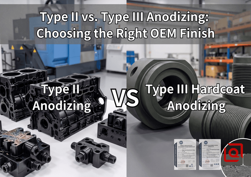
When specifying a custom 6061-T6 or 7075-T6 structural housing for downhole oil tools or subsea enclosures, raw aluminum won't hold up. Unpassivated, its natural oxide film measures a mere 2.5 to 5 nanometers thick—far too thin to survive high-shear abrasive wear or salt fog. Controlled sulfuric acid electrochemical oxidation solves this. But where drawing callouts frequently fail during RFQ releases is conflating MIL-A-8625 Type II sulfuric anodizing with Type III hardcoat. Treat these two processes as equivalent, and your custom OEM assemblies will end up with galled threads, dielectric flashovers, and premature salt-spray failure.
Quick Reference: Type II vs Type III Engineering Baseline
| Parameter | MIL-A-8625 Type II (Class 1/2) | MIL-A-8625 Type III (Class 1/2) |
| Standard Bath Temp | 18°C to 22°C (68°F to 72°F) | -2°C to 4°C (28°F to 39°F) |
| Current Density | 1.2 to 1.5 A/dm² (12-15 ASF) | 2.4 to 3.6 A/dm² (24-36 ASF) |
| Target Coating Thickness | 8 µm to 20 µm (0.0003 to 0.0008 in) | 25 µm to 50 µm+ (0.001 to 0.002+ in) |
| Microhardness (Vickers) | 200 HV to 300 HV | 400 HV to 520 HV (60-65 HRC equivalent) |
| Dielectric Breakdown | ~300 V to 500 V DC | >1500 V DC (at 50 µm thickness) |
| Dimensional Growth | 50% penetrating / 50% outward buildup | 50% penetrating / 50% outward buildup |
| Taber Abrasion Loss | >35 mg loss per 1000 cycles (CS-17 wheel) | <15 mg loss per 1000 cycles (CS-17, 1000g load) |
The Thermal and Electrochemical Reality: Why Bath Temperature Changes Everything
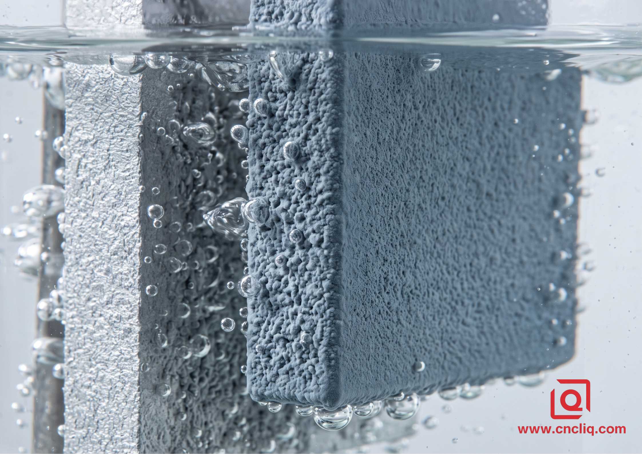
Type II and Type III rely on sulfuric acid baths, but they exist in completely different physical domains. Type II runs around room temp—usually 20°C with an acid concentration hovering between 160 and 200 grams per liter. The electric current drives oxide growth while the ambient electrolyte slightly redissolves the outer pore wall. You get a controlled, porous hexagonal cell structure ideally suited for organic dye absorption. If you want a jet-black anodized finish on a drone chassis, Type II Class 2 gives you vibrant color without blowing past tight dimensional boundaries.
Type III hardcoat is a completely different beast. Drop your chiller settings down to 0°C. Push the voltage up—sometimes past 60V as the resistive barrier layer thickens. What happens at 1.8°C with air agitation running at full tilt? Dissolution slows down almost to zero. You force oxygen ions into the aluminum lattice under aggressive current densities around 3.2 A/dm², building a dense, tightly packed tubular alumina structure.
Here’s a real workshop nightmare we debugged last winter: a client ran a batch of 7075-T6 hydraulic valve blocks through a hardcoat tank, but their chiller solenoid failed mid-cycle. The bath temperature crept from 2°C up to 11°C over a 45-minute span. The result? The solution began aggressively attacking the pore walls. Instead of achieving the required 450 HV hardness, the outer 15 microns turned into a chalky, friable powdery layer with a Taber wear loss of 42 mg per 1000 cycles. Throwing a 7000-series alloy into a warm bath under high current density burns the sharp corners right off the part due to localized current concentration. Maintain fluid circulation across the cathode plates, or throw the whole batch into the scrap hopper.
How Alloy Metallurgy Dictates Anodizing Outcomes
Never send an assembly drawing to an OEM anodizer without verifying your raw material heat number and silicon/copper content. Alloy chemistry dictates how oxide columns nucleate.
-
6061-T6 remains the standard benchmark for anodizing shop floors. Proper pre-treatment etches away its Mg₂Si precipitates cleanly, leaving a homogenous substrate. You get predictable, even dye pickup in Type II runs, whereas Type III builds a dense, olive-drab to slate-gray hardcoat.
-
7075-T6 contains high zinc (5.6-6.1%) and copper (1.2-2.0%). Copper is conductive and non-oxidizable under standard bath parameters. During hardcoating, copper intermetallics cause micro-voids and local current leakage. You need to drop your bath temperature to -1°C and step up voltage slowly to prevent boundary burning.
-
2024-T3 and cast A380 will eat you alive. High copper content in 2024 (topping 4.9%) caps hardcoat growth at ~25–30 µm before micro-cracks form. Meanwhile, cast alloys over 7% silicon block current path; bath acid scours raw aluminum around isolated silicon granules, leaving a blotchy, dark soot that lacks any real abrasion resistance.
Substrate Growth and Tolerance Stack-Ups: The Pre-Machining Math
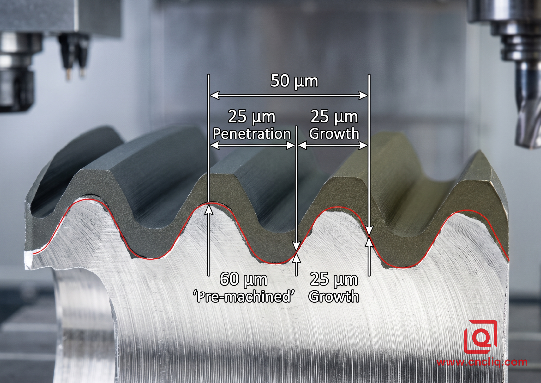
The number one mistake junior mechanical engineers make on 2D drawings is forgetting the "half-in, half-out" rule. Anodizing converts base metal into aluminum oxide (Al2O3).
Rule of thumb: 50% of the total coating thickness penetrates into the substrate, and 50% builds up outward on the surface.
If you specify a 50 µm (0.002 in) Type III hardcoat on a precision 20.000 mm (+0.005/-0.000) bore:
-
Outward growth per side = 25 µm (0.025 mm).
-
Bore internal diameter reduces by 50 µm (0.050 mm) total!
-
Your finished bore shrinks to 19.950 mm. Your bearing will not press in.
For external threads like M12x1.5, a 50 µm hardcoat increases the pitch diameter by 100 µm (4 times the single-side coating growth due to thread flank geometry). Unless you machine the thread undersized prior to plating, the mating nut will gall and seize instantly.
Step-by-Step Action Plan for OEM Procurement
-
Define Finish Callouts on Drawings: Do not write "Anodize Black." Write: "Anodize per MIL-A-8625, Type III, Class 2, Black, 50 µm ± 5 µm thickness. Mask internal threads M6x1.0 prior to processing. Pre-machining dimensions must account for 25 µm single-side growth."
-
Manage Jigging and Rack Marks: Every anodized component needs an electrical contact point. Current levels reaching 3.6 A/dm² will blow off flimsy wire clamps. Require the shop to use titanium spring racks or tapped blind holes on non-critical internal faces. Mark these allowable rack locations on your 2D print.
-
Mandate Post-Anodize Sealing Controls: For Type II outdoor housings, nickel acetate sealing or hot deionized water sealing (96°C to 100°C for 30 minutes) closes the porous cells to pass ISO 9227 neutral salt spray tests beyond 336 hours. That said, skipping the seal keeps Type III anodizing far harder—hitting 500 HV against a sealed 380 HV. For heavy corrosion, spec a dichromate seal. If sliding wear is the main bottleneck, drop the seal or add a PTFE dry-film lube.
-
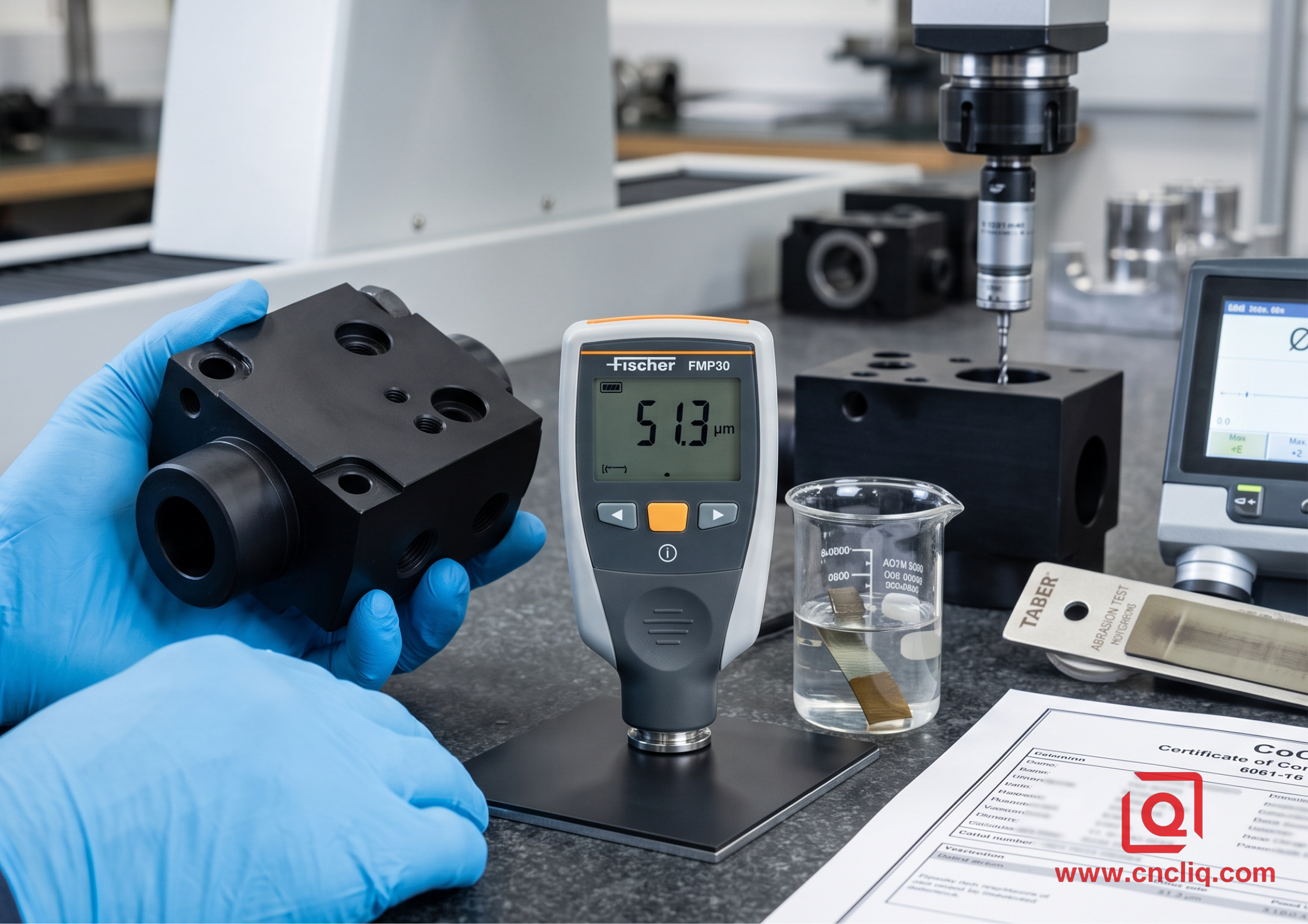
Verify QC Compliance: Require your OEM supplier to deliver a Certificate of Conformance (CoC) including:
-
Eddy current thickness test report per ASTM B244 (minimum 5 spot checks per geometry).
-
Acid dissolution test per ASTM B680 to verify sealing quality.
-
Taber abrasion test certificates per ASTM D4060 if specifying Type III for high-wear sliding sleeves.
-
FAQs
Q1: Can we machine or tap internal threads after applying a Type III Hardcoat?
A: Doable in theory, but it's a tooling eater that blows past tight tolerances. Sitting at 400–520 HV (around 60–65 HRC), Al2O3 wrecks tooling fast. Standard carbide taps and end mills will notch, micro-chip, or outright snap upon impact. If an internal thread or critical bearing bore requires post-anodize line-boring, you must either mask the feature with silicone plugs/liquid resist prior to immersion or leave a generous pre-machining grinding stock to pass the diamond-coated tooling through. The best practice for OEM assemblies is always to thread prior to anodizing, calculate the 4x single-side thread pitch growth on pitch diameter, and chase the threads with an over-sized or under-sized tap during the primary CNC setup.
Q2: Why did our black anodized 7075-T6 aluminum parts fade to a brownish/purple tint after UV exposure?
A: This fading (known as photo-degradation) usually stems from two root causes: using low-grade organic azo dyes during Type II Class 2 processing, or inadequate sealing parameters. Standard organic black dyes decompose when subjected to solar radiation or intense thermal cycling. For outdoor enclosure parts or high-temperature marine environments, specify inorganic metal-complex dyes or electrolytic coloring (two-step tin or cobalt coloring). Furthermore, verify that your supplier executes a hot nickel acetate seal at 96°C to 100°C for a minimum of 2.5 to 3 minutes per micron of coating depth. A poorly sealed porous cell allows atmospheric moisture and UV light to leach out dye molecules, triggering color drift.
Q3: What is the dielectric breakdown voltage of a 50 µm Type III Hardcoat, and can it act as an electrical insulator?
A: For an unsealed, fully dense 50 µm (~2 mil) Type III hardcoat, you’ll typically measure breakdown around 1500–2200 VDC. Clean alloys like 6061-T6 yield far better dielectric consistency than high-copper grades like 2024-T3. That said, never rely on anodizing alone as a primary high-voltage barrier in power electronics. Thermal expansion mismatch (aluminum at ~23 × 10⁻⁶/K vs. alumina at ~8 × 10⁻⁶/K) naturally induces micro-fissuring, and rack-mounting marks can easily create pinpoint leakage paths. If the isolation is safety-critical, 100% hi-pot or spark testing on the line isn't optional—it's mandatory.
Q4: How does surface roughness (Ra) change before and after Type II vs Type III Anodizing?
A: Anodizing always alters the surface topography of precision machined components. Type II anodizing (10 µm-15 µm thickness) typically causes a minor increase in surface roughness, adding roughly Ra 0.2 µm to Ra 0.4 µm to the pre-machined substrate. However, Type III hardcoating (50 µm thickness) drastically changes surface texture due to aggressive cellular growth and columnar cell enlargement; a smooth Ra 0.8 µm milled finish can easily degrade to Ra 1.6 µm or Ra 2.5 µm post-hardcoating. If your application involves dynamic hydraulic rod seals or high-speed sliding contacts, you must specify a pre-anodize polishing stage (Ra < 0.2 µm) or perform a post-anodize micro-lapping/diamond-honing operation to restore seal-friendly surface finishes.
Q5: If a batch of anodized OEM parts fails inspection, can the coating be stripped and re-anodized without scrapping the aluminum parts?
A: Yes, anodized layers can be chemically stripped using a hot chromic-phosphoric acid bath (which dissolves the oxide without attacking the raw aluminum substrate) or a caustic soda (NaOH) bath. However, there is a severe dimensional penalty. Caustic stripping etches the underlying base metal, removing an additional 5 µm to 15 µm of substrate material per cycle. If you strip a 50 µm hardcoat from a precision bore, the final internal diameter will permanently expand by 30 µm to 60 µm beyond the original pre-machining dimensions. Stripping and re-anodizing is viable for wide-tolerance structural brackets, but for tight-tolerance CNC parts with ±0.010 mm limits, chemical stripping almost certainly pushes the dimensions out of print and into the scrap bin.
Summary
Picking Type II over Type III anodizing isn't about optics—it's a core engineering decision driving part wear life, fit tolerances, and long-term field survivability. Type II offers solid corrosion protection and clean decorative tints for standard housings. Type III hardcoat, however, builds a thick, ceramic-grade jacket built for high friction, marine salt-spray, and strict dielectric requirements. Accounting for alloy composition, bath temperature, and anodize build-up directly in your CAD models and drawing callouts prevents line downtime, stops field returns, and guarantees batch-to-batch consistency.
Contact Information
Disclaimer
All technical articles, material specifications, machining recommendations, and surface treatment details published on this blog are for informational and reference purposes only. Please note that general blog insights do not replace signed technical agreements. Because custom parts vary by material heat numbers, machine calibrations, and specific tolerances, binding quality specs are governed solely by your approved CAD drawings, signed contracts, and formal quality plans.
All customer case studies featured on this blog have been thoroughly anonymized and sanitized. The performance metrics, manufacturing workflows, and imagery displayed serve solely to demonstrate our custom machining capabilities and do not represent a single universal standard for all orders.
Liqin Manufacturing Team
Built on 18 years of precision engineering experience, Ningbo Liqin Industry manufactures high-tolerance metal components for demanding global markets. We operate out of a 6,500 m² production hub equipped with over 150 machines, running 4-axis and 5-axis CNC machining, mill-turn machining, cold extrusion, and pressure die casting under one roof. This setup allows us to manage projects seamlessly, taking parts from initial CAD concepts directly to finalized shipments.
We handle quality control with zero compromise. We treat tight tolerances with the engineering discipline they require. Backed by ISO 9001, ISO 13485, and IATF 16949 certifications, our QA engineers run strict IPQC, FQC, and OQC checks on every single production batch. From CMM dimensional mapping and optical profiling to hardness and salt-spray testing, we validate your critical specs upfront—so you receive drop-in ready components with zero assembly headaches or costly line stoppages. On top of manufacturing, you can rely on us for two-hour response times on new RFQs, direct support for prototype sampling, and smooth export shipping across Europe, North America, Asia, and Oceania.
Welcome your inquiries and samples. Visit our website or contact us directly for a competitive quote!
