 English




Are you still trying to decide whether Type I chromic acid anodizing belongs on a fatigue-sensitive aerospace aluminum part, or whether a newer non-chromate process should replace it? A short finish note can hide several expensive questions. Will trapped electrolyte remain in a lap joint? Will a bearing bore still fit after processing? Does the coating need to accept primer? Who owns salt-spray testing, masking, lot traceability, and approval of an alternative finish? This guide answers those questions from the manufacturing floor, where the correct anodize is the one that matches the drawing, alloy, geometry, assembly, approved processor, and inspection plan.
Type I chromic acid anodizing is a thin anodic oxide treatment for aluminum. It combines corrosion protection, a useful paint base, low dimensional impact, and less fatigue penalty than thicker anodic coatings. It is not a wear coating and must not be substituted by name alone. Start every RFQ with the controlled drawing and current governing specification.
1. The Short Answer: When Type I Is a Strong Candidate
Choose Type I for discussion when the part is aluminum, corrosion protection is important, the geometry is fatigue-sensitive or dimensionally delicate, and the drawing or approved customer specification explicitly permits chromic acid anodizing. Typical candidates include thin aerospace brackets, hinge fittings, avionics frames, lightly loaded actuator supports, and machined parts that will receive an approved primer or paint system.
Do not choose it automatically for sliding wear, a hard bearing surface, a decorative black finish, or an electrically conductive mating face. Those needs point toward another finish or a masked area. Type III hard anodizing is normally the conversation for abrasion and galling. A conversion coating may suit a conductive paint base with negligible dimensional change. Type IC or Type IIB can be considered as non-chromate alternatives only when the design authority approves them.
The official MIL-PRF-8625 document record identifies six anodic coating types and two classes for non-architectural aluminum applications. It defines Type I as conventional chromic acid anodizing, Type IB as a low-voltage chromic process, Type IC as a non-chromic alternative, Type II as conventional sulfuric anodizing, Type IIB as thin sulfuric anodizing, and Type III as hard anodizing. Avoid the vague note “aircraft anodize.”
|
Selection question |
Type I practical answer |
RFQ implication |
|
Is the part fatigue-sensitive? |
Thin Type I is commonly considered where a thick brittle oxide would be undesirable |
Mark fatigue-critical zones and provide the approved specification |
|
Is severe sliding wear the main risk? |
Type I is not the normal wear solution |
Review Type III, inserts, or a local wear treatment |
|
Will the part be primed or painted? |
Type I can provide an effective base when the approved seal and paint system are coordinated |
State whether paint adhesion or maximum corrosion protection controls sealing |
|
Are tight bores, threads, or ground paths present? |
Dimensional change is small but still needs planning |
Identify finished dimensions, masking, plugs, and contact points |
|
Is a chromate-free finish mandatory? |
Conventional Type I uses a chromic acid bath |
Ask the design authority whether Type IC or Type IIB is approved |
|
Is the drawing a legacy aerospace drawing? |
Do not modernize the finish without written approval |
Quote to the drawing, then submit a controlled deviation if needed |
2. What the Process Actually Does to Aluminum
Anodizing is electrochemical conversion, not a layer of metallic chromium plated onto the component. The aluminum workpiece becomes the anode in an acid electrolyte. Electrical energy converts a controlled portion of the surface into aluminum oxide. That oxide is integral with the base metal and contains microscopic pores before sealing. A specified seal changes those pores and improves the barrier performance.
This distinction matters at drawing review. A plated layer can be discussed mainly as added material. An anodic coating consumes some aluminum while part of the oxide extends outward. For Type I, the film is thin enough that dimensional change is usually modest, yet modest is not the same as zero when a dowel bore, precision thread, bearing seat, or bond area is involved.
The current MIL-PRF-8625 framework controls Types I and IB primarily by unsealed coating mass rather than by a universal nominal thickness. Its minimum for Type I and IB is 200 mg/ft². The specification guidance gives a broad thickness range of 0.00002 to 0.0007 inch for Types I, IB, IC, and IIB, while the actual result varies with alloy and process. That broad range is a reason to avoid copying a thickness from a blog into a purchase order. If thickness or finished size is functionally important, put the requirement and measurement method on the controlled manufacturing documents.
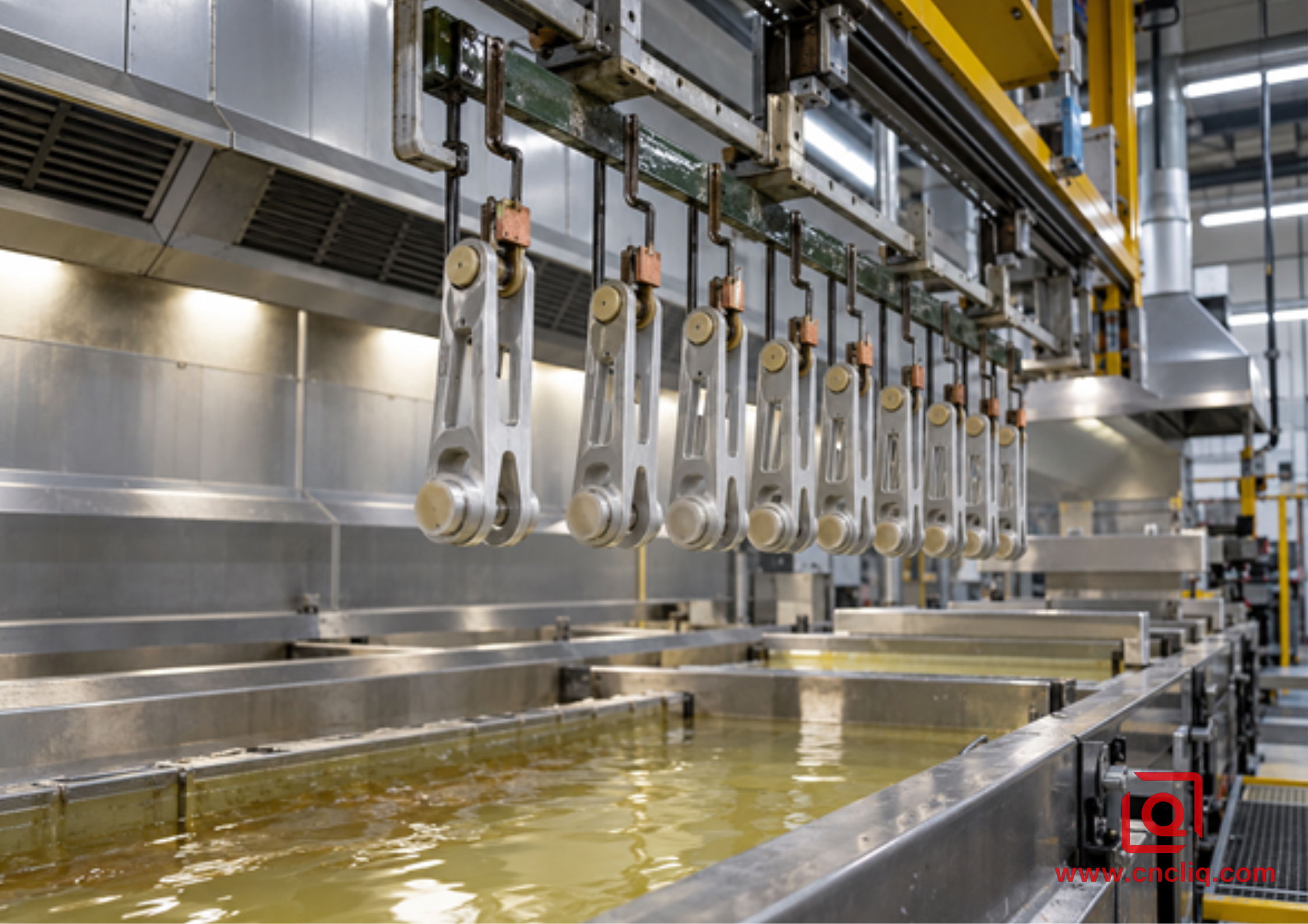
Aerospace aluminum clevises on a controlled anodizing process rack
Figure 1. Thin, masked clevis-style parts illustrate why rack contact, drainage, and protected bearing bores should be settled before processing.
2.1 Cleaning, racking, anodizing, and sealing
A reliable route starts before the tank. Oil, marking residue, embedded abrasive, and inconsistent native oxide can create local defects. The process sequence needs controlled cleaning and deoxidizing suitable for the alloy. The parts are then racked so electrical contact is stable and contact marks fall in approved locations. Geometry must drain freely. Blind cavities, rolled seams, and porous castings deserve special review because retained solution can attack a component after the visible surface looks acceptable.
During anodizing, voltage, time, solution condition, alloy chemistry, and rack conductivity interact. The buyer specifies required performance and the approved standard; the qualified processor controls the operating window.
Unless the drawing says otherwise, MIL-PRF-8625 requires Types I, IB, IC, II, and IIB to be sealed. The approved sealing route matters because corrosion behavior, paint adhesion, electrical behavior, and downstream bonding needs can conflict. A finish intended as a paint base should not be treated as interchangeable with a fully sealed stand-alone corrosion barrier without checking the applicable process specification.
2.2 Why Type I fits many aerospace geometries
Aircraft aluminum parts often combine thin ribs, high local stress, reamed holes, rivet interfaces, and protective organic coatings. Type I addresses that combination better than a thick wear-focused oxide. Its low coating mass adds little weight, changes dimensions less than common Type II or Type III coatings, and provides corrosion protection where bare high-strength aluminum would be vulnerable.
The benefit is not that Type I makes aluminum stronger. It does not. Its value is that the coating is thin enough to protect the surface while limiting the fatigue debit associated with thicker anodic films. MIL-PRF-8625 specifically notes the use of Types I or IB on fatigue-critical components because of their thinness. That wording supports a selection discussion; it does not replace structural substantiation by the design authority.
3. Type I Versus Type IC, Type II, Type III, and Conversion Coating
The wrong comparison asks, “Which coating is best?” The useful comparison asks, “Which failure mode must this surface prevent?”
|
Finish family |
Primary reason to consider it |
Dimensional effect |
Important limitation |
|
Type I chromic acid anodize |
Corrosion protection, paint base, fatigue-sensitive aluminum, legacy aerospace approval |
Low relative to thicker anodize |
Uses a Cr(VI)-containing process bath and requires controlled special processing |
|
Type IC non-chromic anodize |
Approved alternative where Type I-like corrosion, paint, and fatigue performance is needed |
Low |
Not automatically interchangeable; design approval is required |
|
Type IIB thin sulfuric anodize |
Thin non-chromate alternative in approved applications |
Low |
Electrolyte-entrapment behavior may differ from Type I |
|
Type II sulfuric anodize |
General corrosion protection and decorative color |
Moderate |
Greater dimensional and fatigue impact than a thin Type I coating |
|
Type III hard anodize |
Wear resistance, abrasion, and some dielectric applications |
Highest among these anodize types |
Can reduce fatigue performance and close precision features |
|
MIL-DTL-5541 conversion coating |
Paint base, corrosion resistance, and electrical-contact strategies with negligible buildup |
Very low |
Less abrasion resistance than anodizing |
For a broader sulfuric-anodize comparison, Liqin’s Type II versus Type III anodizing guide explains why a finish chosen for color should not be confused with one chosen for wear. The powder coating versus anodizing guide is useful when an assembly needs a thicker colored barrier rather than an integral oxide.
Type IC deserves special attention on new programs. MIL-PRF-8625 defines it as a non-chromic alternative for the corrosion resistance, paint adhesion, and fatigue-resistance roles associated with Types I and IB. However, the same specification cautions that Type IC and Type IIB may not be suitable replacements when electrolyte entrapment is the primary concern. Environmental preference does not erase geometry.
4. Corrosion Performance: What the 336-Hour Test Means
MIL-PRF-8625 calls for a 5 percent salt-spray test in accordance with ASTM B117, with specific specimen orientation and 336 hours of exposure for the covered corrosion-resistance test. The acceptance criteria are more precise than “no rust.” Aluminum does not rust like carbon steel, and visual discoloration is not automatically a pit. The specification limits isolated pits and excludes defined edge, marking, and contact areas from the evaluated surface.
This test is a controlled quality-conformance tool. It is not a direct forecast that an aircraft part will last exactly 336 hours, 336 days, or any fixed service interval. Field performance also depends on alloy, joint design, drainage, seal quality, primer, topcoat, galvanic couples, scratches, maintenance, and the real atmospheric environment.
A strong purchase order names the coating specification, type, class, seal or approved process specification, required testing, sampling plan, and documentation. If the part will be painted, the organic coating stack and preparation window must also be identified. If salt-spray panels rather than production parts will be tested, the plan should state how the panels represent the production load.
4.1 Why surface condition still matters
Anodizing follows the existing surface. It does not fill tool marks, porosity, embedded media, or edge damage. Alloy chemistry also affects appearance: 2024, 7075, clad sheet, cast aluminum, and 6000-series alloys need not emerge with the same shade. Define whether roughness and dimensions apply before or after finish. If visual uniformity is a true acceptance criterion, approve representative coupons or a limit sample instead of relying on an adjective such as “perfect silver.”
5. DFM Rules Before the First Chip Is Cut
The cheapest finishing problem is the one removed during drawing review. Liqin’s guide to aluminum alloy selection and surface finishing provides the wider material context, while the rules below focus on Type I aerospace work.
5.1 Separate finished dimensions from pre-anodize dimensions
State whether a dimension applies before or after anodizing. The distinction is essential on press fits, bearing seats, reamed holes, dowel locations, thread pitch diameters, seal lands, and thin flexures. Type I usually causes far less buildup than hardcoat, so copying a “50/50 growth rule” from a Type III job can create a bad compensation. Use the approved processor’s demonstrated data for the alloy, pretreatment, geometry, and specification.
5.2 Place rack contacts deliberately
Every anodized part needs electrical contact. A contact mark on a hidden non-functional boss may be acceptable; the same mark on a seal land or visible surface may reject the part. Mark permissible contact zones on the drawing or process sketch. Give the processor more than one viable location when the geometry allows it.
5.3 Design drainage and prevent entrapment
Blind intersecting holes, tight lap joints, rolled edges, porous castings, and capped tubes can retain electrolyte. Add drain paths where design permits, separate assemblies before processing, or define special rinsing and bake requirements through the approved specification. The custom anodized aluminum manifold shows how intersecting passages and threaded ports complicate cleaning and masking, although its drawing-specific finish must not be assumed to be Type I.
5.4 Control edges, holes, and masking
Break sharp edges consistently. Extremely sharp corners can produce a fragile oxide and are more easily damaged in handling. Identify surfaces that must remain electrically conductive, areas used for adhesive bonding, threaded inserts installed after finish, and bores that cannot accept even small dimensional movement. Mask only for a functional reason; unnecessary masking adds handling, leakage risk, and cost.
5.5 Keep dissimilar-metal assembly out of the tank
Steel inserts, stainless pins, copper components, and mixed-metal assemblies can complicate pretreatment and create galvanic or chemical risks. When practical, machine and anodize the aluminum component first, inspect it, then install the approved insert. If an insert must be present during finishing, the qualified processor and design authority need to review it before quotation.
6. A Shop-Floor Manufacturing and Quality Plan
Type I anodizing is only one operation in the route. The outcome depends on how machining, deburring, cleaning, special processing, and final inspection connect.
1. Contract review: Confirm the current drawing revision, material and temper, Type I callout, class, seal, applicable customer specification, masking, contact locations, test requirements, and approved processor status.
2. Material control: Maintain material certificates and heat or lot traceability. Segregate alloys and tempers because different chemistries can respond differently in pretreatment and anodizing.
3. CNC process planning: Select datums that survive the full route. Use stable fixturing for thin walls and finish critical holes with the post-anodize requirement in mind. Liqin’s article on multi-axis machining of complex aluminum geometries shows why reducing re-clamping helps preserve position on aerospace-style parts.
4. Deburring and cleaning review: Remove burrs without rolling material into holes or changing controlled edges. Prohibit silicone, uncontrolled marker, and abrasive contamination that the finisher has not approved.
5. First-article measurement: Record critical raw dimensions so the team can distinguish machining variation from finishing variation. Keep photographs of designated rack and masking zones.
6. Special processing: Send a traveler that identifies every controlled requirement. Verify that the processor’s scope and customer approvals match the job, not merely the generic process name.
7. Final inspection: Check dimensions that apply after finish, coating appearance, masked areas, contact marks, threads, and cleanliness. Review certificates against the purchase order and lot identity.
8. Performance evidence: When required, review coating-mass, corrosion, paint-adhesion, or other process-control records. Do not treat a generic certificate as evidence for an unlisted test.
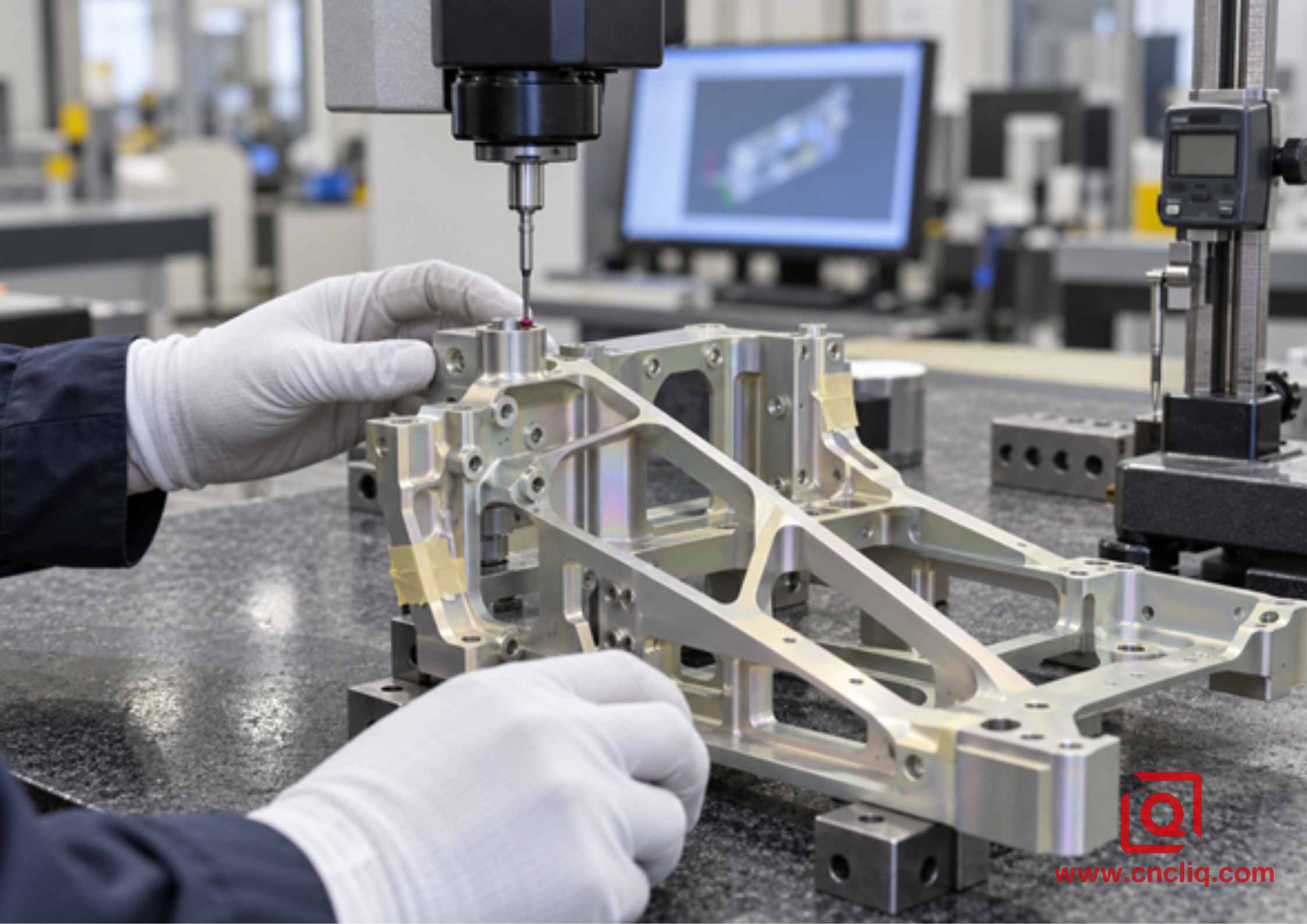
CMM inspection of a thin-rib Type I anodized aerospace frame
Figure 2. Post-finish inspection should concentrate on functional datums, protected interfaces, and features whose acceptance applies after anodizing.
6.1 What to put in a useful RFQ package
A useful RFQ contains a native 3D model, a controlled 2D drawing, annual and release quantities, material and temper, finished-dimension rules, finish specification and revision, class, seal, masking map, rack-contact zones, inspection level, certificate needs, and any customer-approved special-process list.
If the drawing only says “Type I anodize,” ask who owns the remaining choices before production. An apparently small omission can decide whether the part receives dye, which seal is used, how a paint system bonds, and whether a functional surface remains conductive. Send the assembly context as well. A finisher cannot infer that a bare pad is an electrical ground or that a bore accepts a flight-critical spherical bearing.
For a fast manufacturing review, include STEP and PDF files plus your target quantity and delivery window in a direct RFQ to Liqin. The engineering response should identify open finish questions before price and lead time are frozen.
7. Anonymous Aerospace Case: 7075-T651 Actuator Support
The following anonymized composite case is a realistic custom-machining example, sanitized to explain the method rather than disclose a customer program.
An aerospace equipment integrator needed a small batch of Y-shaped actuator supports machined from 7075-T651 plate. Each part carried a spherical bearing, two dowel-controlled mounting points, and deep lightening pockets. The legacy drawing called for MIL-PRF-8625 Type I, Class 1, followed by an approved primer on selected faces. Yet it did not say whether the bearing bore applied before or after anodizing. A blind intersection could retain solution, and the only obvious rack point sat beside a bonding pad.
The team clarified that the bearing bore and dowel holes would be accepted after finish, protected the bearing seat under an approved masking plan, and opened the cross-hole into a drainable geometry after design approval. A temporary machining tab became the permitted rack contact. Critical features were measured before and after the first finishing lot so a demonstrated allowance, not a borrowed universal rule, could guide production.
The supports were rough-machined with balanced stock, released from high clamp pressure, re-probed, and finished in one multi-axis setup. The approved processor received a marked masking and contact sketch. Final inspection covered true position, bearing fit, contact marks, finish continuity, certificates, and specified process evidence.
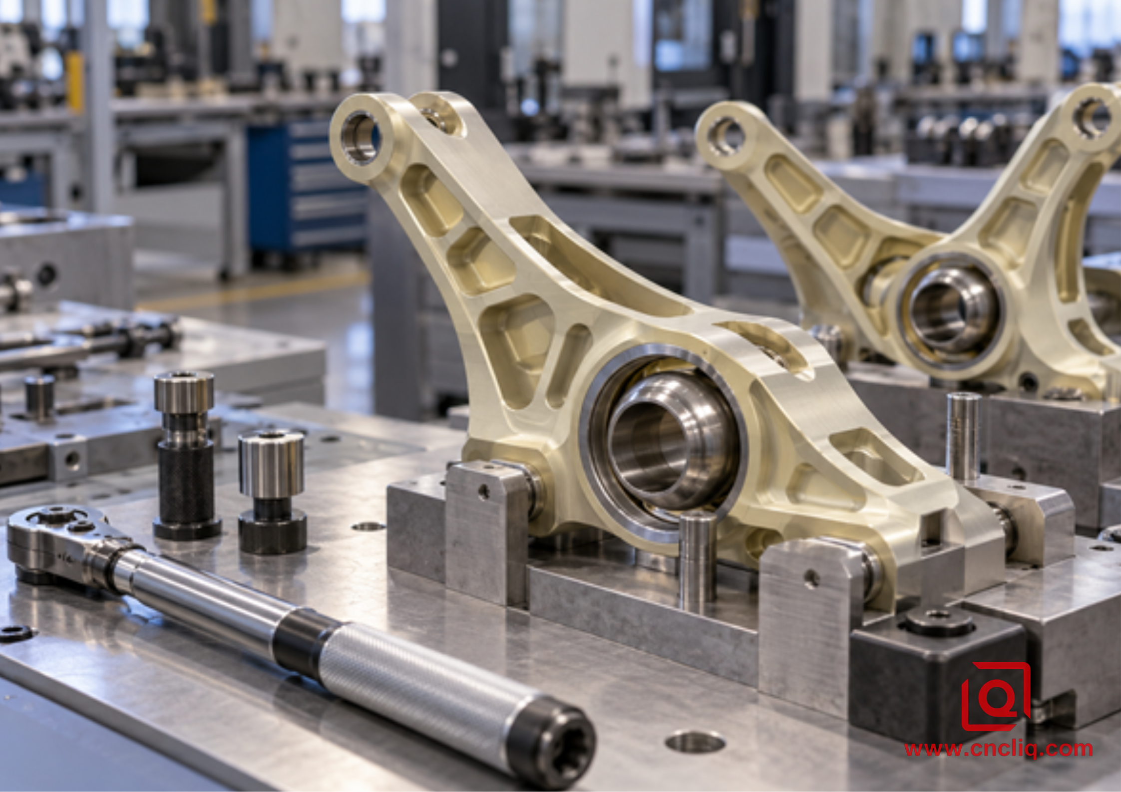
Finished Type I anodized actuator supports at a bearing-fit assembly fixture
Figure 3. A functional fit check complements dimensional inspection where a protected bearing seat, anodized structure, and hardware meet.
Defining these interfaces before release reduced masking ambiguity and made the quote more accurate. More importantly, the first article answered the dimensional question before production rather than after a rejected assembly.
8. Inspection and Documentation That Build Buyer Confidence
Aerospace sourcing teams buy a controlled result with traceability, not a color. Match the evidence to part risk. A typical package may include material certificates tied to the traveler, a First Article Inspection or dimensional report, a Certificate of Conformance naming the coating type, class, specification revision, processor and lot, required process-control test evidence, masking and rack-contact acceptance, and written disposition of any deviation. Packaging must prevent metal-to-metal rubbing, trapped moisture, and damage to thin ribs. Do not request every test by habit; special coupons, 100 percent inspection, unique masking, and custom packaging add cost. Request what the design and quality plan need, then state it clearly enough to quote.
9. Environmental and Worker-Safety Reality
Chromic acid contains hexavalent chromium. OSHA’s electroplating and anodizing guidance explains that workers can be exposed to Cr(VI) mist during chromic-acid processes and describes engineering controls, work practices, personal protective equipment, and respiratory protection considerations. The U.S. EPA description of chromium anodizing identifies the process as one used mainly for aircraft parts and other structures subject to stress and corrosive conditions.
For buyers, this has two consequences. First, Type I must be sourced through a properly controlled and legally compliant special-process operation. Second, new programs should evaluate approved non-chromate options instead of carrying a legacy finish forward without review. Neither point authorizes an informal substitution. Aerospace drawings, customer specifications, regulatory requirements, and approved supplier lists still govern.
Ask prospective suppliers how they control subcontracted special processing, verify certifications, preserve lot traceability, and manage nonconforming output. A machine shop that sends parts out for anodizing still owns the manufacturing interface promised to the customer.
FAQs
1. Is Type I chromic acid anodizing the same as chrome plating?
No. Chrome plating deposits metallic chromium onto a substrate, while Type I anodizing electrochemically converts the aluminum surface into an integral aluminum oxide film in a chromic acid electrolyte. The part is the anode, and the resulting finish is thin, corrosion-resistant, and often used as a paint base. Calling it chrome plating on an RFQ can lead to the wrong supplier, the wrong process, and a serious compliance error.
2. How thick is MIL-PRF-8625 Type I anodizing?
MIL-PRF-8625 controls Type I and IB by a minimum unsealed coating mass of 200 mg/ft² and provides broad thickness guidance rather than one mandatory universal thickness. The published range for Types I, IB, IC, and IIB is 0.00002 to 0.0007 inch, but actual thickness depends on alloy and process. If finished size depends on the film, specify the dimensional requirement and validate it with the approved processor.
3. Can Type IC replace Type I on an existing aerospace drawing?
Only with the required design and customer approval. Type IC is defined as a non-chromic alternative for applications needing corrosion resistance, paint adhesion, and fatigue resistance, but it is not automatically equivalent in every geometry. MIL-PRF-8625 notes that non-chromate alternatives may not suit cases where electrolyte entrapment is the main concern, so a documented engineering change or deviation is essential.
4. Does Type I anodizing pass 336 hours of salt spray?
The MIL-PRF-8625 corrosion-resistance test uses 5 percent salt spray in accordance with ASTM B117 for 336 hours and applies defined pit limits and evaluation rules. Passing that controlled test demonstrates conformance to the specified requirement; it does not convert directly into a service-life promise. Real aircraft performance also depends on alloy, sealing, primer, topcoat, drainage, scratches, galvanic couples, and maintenance.
5. What should I send for a Type I anodized aerospace-part quotation?
Send the STEP model, controlled 2D drawing, material and temper, MIL-PRF-8625 type and class, any customer process specification, finished-dimension rules, masking and rack-contact map, annual and release quantities, inspection level, certificate needs, approved processor requirements, destination, and delivery target. If a finish detail is unresolved, identify it openly so engineering can price a clarification or first-article trial instead of burying an assumption in production.
Summary
Type I chromic acid anodizing remains a practical corrosion-protection and paint-base option for many fatigue-sensitive aerospace aluminum parts because it delivers a thin integral oxide with limited dimensional impact. Successful sourcing depends on more than naming the process: lock the current specification, alloy, class, seal, finished dimensions, masking, drainage, rack contacts, test plan, approved processor, and traceability before release. For new programs, evaluate approved Type IC or Type IIB alternatives, but never substitute without design authority. Send Liqin your drawings, quantities, and finishing requirements for a manufacturability review and a quotation built around the complete machining-to-finish route.
Contact Information
Company: Ningbo Liqin Industry Co., Ltd.Daily customer maintenance & after-sales support:service@shturl. zhuwanying@cncliq.com
New inquiry, quotation & order discussion:business@shturl. zhouli@chinaliqin.com
Hotline: +86 18757148656
Disclaimer
All technical articles, material specifications, machining recommendations, and surface treatment details published on this blog are for informational and reference purposes only. Please note that general blog insights do not replace signed technical agreements. Because custom parts vary by material heat numbers, machine calibrations, and specific tolerances, binding quality specs are governed solely by your approved CAD drawings, signed contracts, and formal quality plans.
All customer case studies featured on this blog have been thoroughly anonymized and sanitized. The performance metrics, manufacturing workflows, and imagery displayed serve solely to demonstrate our custom machining capabilities and do not represent a single universal standard for all orders.
Liqin Manufacturing Team
Built on 18 years of precision engineering experience, Ningbo Liqin Industry manufactures high-tolerance metal components for demanding global markets. We operate out of a 6,500 m² production hub equipped with over 150 machines, running 4-axis and 5-axis CNC machining, mill-turn machining, cold extrusion, and pressure die casting under one roof. This setup allows us to manage projects seamlessly, taking parts from initial CAD concepts directly to finalized shipments.
We handle quality control with zero compromise. We treat tight tolerances with the engineering discipline they require. Backed by ISO 9001, ISO 13485, and IATF 16949 certifications, our QA engineers run strict IPQC, FQC, and OQC checks on every single production batch. From CMM dimensional mapping and optical profiling to hardness and salt-spray testing, we validate your critical specs upfront—so you receive drop-in ready components with zero assembly headaches or costly line stoppages. On top of manufacturing, you can rely on us for two-hour response times on new RFQs, direct support for prototype sampling, and smooth export shipping across Europe, North America, Asia, and Oceania.
Welcome your inquiries and samples. Visit our website or contact us directly for a competitive quote!
