 English




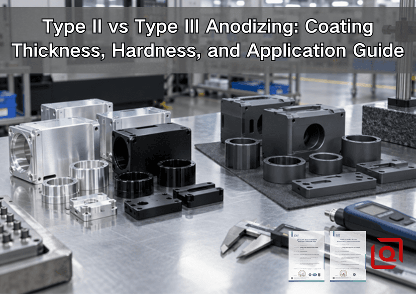
Are you still unsure whether a drawing should call for Type II anodizing or Type III hardcoat? The wrong choice can create a good-looking part that wears out too early, or a durable coating that closes a bearing bore and stops assembly. This guide explains the decision from a shop-floor point of view. We will follow the part from drawing to inspection and pause where jobs usually go wrong: at the thickness note, a masked bore, a color sample, or an RFQ that leaves the finisher guessing.
On most jobs, the fork in the road is easy to see. Type II serves the color-and-corrosion brief. Type III belongs on a surface that must keep working while it rubs or wears. The final choice is still part-specific. A 10 µm black coating on an enclosure and a 50 µm hardcoat inside a hydraulic bore solve different problems, even though both begin with sulfuric-acid anodizing.
This article focuses on decisions that affect custom CNC machined aluminum parts. For a wider view of bead blasting, conversion coatings, powder coating, and their tolerance effects, use Liqin’s aluminum OEM surface finishing guide as the companion pillar page.
Type II vs Type III anodizing at a glance
|
Engineering point |
Type II sulfuric anodizing |
Type III hard anodizing |
|
Primary purpose |
Corrosion protection, color, appearance |
Wear, abrasion, and durable functional surfaces |
|
Common shop target |
5–25 µm |
25–75 µm |
|
Broader MIL-PRF-8625F range |
1.8–25.4 µm |
12.7–114.3 µm |
|
Typical microhardness |
About 200–400 HV; process and alloy dependent |
About 400–600 HV; process and alloy dependent |
|
Color behavior |
Clear or widely dyeable |
Natural gray, bronze, charcoal, or black; bright color control is limited |
|
Dimensional effect |
Usually modest, but relevant to tight fits and threads |
Often significant; allowance or masking is normally required |
|
Wear resistance |
Suitable for light handling and limited rubbing |
Preferred for repeated sliding, abrasive contact, and bearing surfaces |
|
Relative process cost |
Lower |
Higher because of colder bath control, higher current density, longer time, and tighter inspection |
|
Typical parts |
Enclosures, brackets, trim, color-coded hardware |
Valve blocks, piston sleeves, guide rails, tooling, high-duty mechanisms |
These are comparison values, not universal purchase limits. MIL-PRF-8625F defines the 2 types; ISO 7599 and ISO 10074 cover protective/decorative and hard anodizing. The approved drawing and quality plan control the job.
What anodizing actually changes
Anodizing is not paint. Inside the bath, the outer skin of the aluminum itself is turned into oxide. Part of the oxide penetrates the original surface and part grows outward. Before sealing, its pores can accept dyes or other approved treatments.
Cleaning, desmutting, racking, current distribution, bath control, rinsing, dyeing, and sealing all affect the result. Type III normally uses a colder bath and higher current density to build its thicker, denser wear layer.
Type alone is incomplete. One small callout makes a big difference: Class 1 is non-dyed; Class 2 adds dye. Then finish the note properly. Put the alloy, thickness, color, seal, final dimensions, mask map, rack marks, tests, and acceptance limits on the drawing.
Coating thickness: the number that changes the design
The broad window in MIL-PRF-8625F runs from about 1.8–25.4 µm for Type II and 12.7–114.3 µm for Type III. On production travelers, the band is usually tighter—often 5–25 µm for Type II and 25–75 µm for Type III. The correct value depends on service, alloy, geometry, class, and the qualified process; more thickness is not automatically better.
A decorative housing may need only Type II for color and corrosion, while a gritty sliding guide may justify controlled Type III. Do not specify maximum thickness without a functional reason.
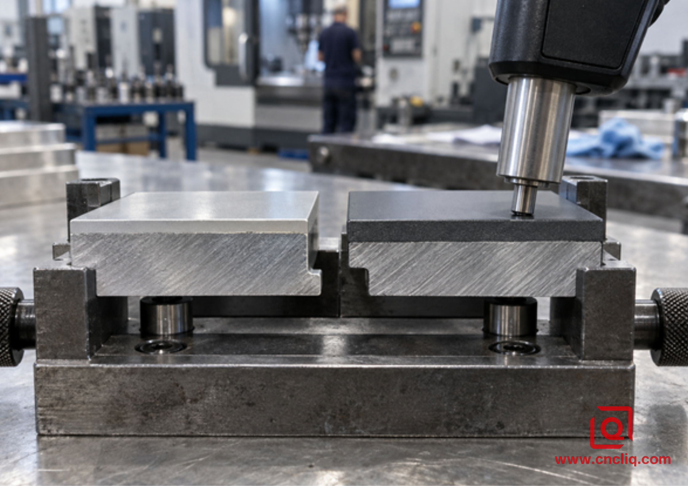
Coating thickness is verified on accessible, representative surfaces using a calibrated method.
The 50/50 growth rule—and where it can mislead
A common estimating rule says roughly half of the anodic layer penetrates the original aluminum surface and half builds outward. It is useful for early tolerance planning, but it is not a substitute for a qualified finisher’s measured growth factor. That split moves with the alloy, bath, target thickness, local geometry, current density, and the metal removed during pre-treatment. For a bearing seat or valve bore, measured capability and a first article beat any rule of thumb.
Take a 20.000 mm bore and a 50 µm hardcoat. With 25 µm building inward from each wall, the arithmetic points to 19.950 mm after coating—a 0.050 mm loss in diameter. That is enough to destroy many bearing or slip fits. The practical choices are to open the bore before coating, mask it, or finish it afterward if the design and coating system permit. State whether the drawing dimension applies before or after anodizing.
|
Feature |
Coating risk |
Typical engineering response |
What the drawing should say |
|
Precision bore |
Diameter closes |
Pre-machine allowance or mask |
Finished size and whether it is post-anodize |
|
External journal |
Diameter grows |
Machine undersize or mask |
Coating thickness and final fit |
|
Internal thread |
Pitch diameter tightens; brittle oxide may chip |
Mask or compensate with approved thread strategy |
Mask depth, thread class, gauge after finish |
|
Grounding pad |
Anodic layer is electrically insulating |
Mask the contact area |
Location and maximum masked boundary |
|
Sharp edge |
Current concentrates and coating may burn or become fragile |
Add a practical radius or chamfer |
Edge break before finish |
For more detail on alloy movement, machining allowances, and the sequence from billet to finished part, see Liqin’s aluminum OEM machining and surface treatment workflow. The same rule applies to quoting: a 3D model alone cannot communicate which interfaces may receive coating. A marked 2D drawing is still the clearest manufacturing contract.
Hardness and wear: related, but not identical
For a working comparison, many Type II films fall near 200–400 HV; a controlled Type III hardcoat is commonly reported near 400–600 HV. Treat these as comparison ranges, not guaranteed values or casual Rockwell C equivalents. For a hardness CTQ, specify test method, load, location, coupon, and acceptance range.
Hardness tells only part of the wear story. The headline number can hide a weak setup. Too little film, poor substrate support, an edge crack, trapped grit, or a bad mating pair can undo the apparent hardness. Before calling hardcoat a bearing surface, check speed and pressure, then the lubricant, debris, and working temperature. Sealing closes pores and helps corrosion resistance. The trade-off is real: an approved unsealed hardcoat may retain better abrasion behavior in a wear-led design. The application requirement must decide the trade-off.
Use Type II for light contact, indoor brackets, housings, and color-coded parts. Pay for Type III when repeated rubbing, loaded sliding, abrasive particles, or tool contact justifies it.
Corrosion, sealing, and color expectations
A type callout alone does not earn a corrosion pass. The result still carries the mark of the alloy, surface defects, film thickness, rinse and seal, and the environment outside the tank. A Type II or Type III note does not promise a particular ASTM B117 duration. Write the hours, specimen orientation, evaluation method, and allowable corrosion into the quality plan.
Type II accepts many dyes. Type III tends toward gray, bronze, olive, charcoal, or black, with shade affected by alloy and thickness. Approve a physical range sample, not a screen color; for assemblies, one heat lot and finishing batch improve consistency.
Alloy choice changes the anodized result
Base-metal chemistry changes the finish. 6061-T6/T651 is a forgiving all-round choice that usually gives consistent Type II color and dependable Type III hardcoat. Liqin’s 6061 aluminum machining guide covers the cutting and fixturing controls required before finishing.
Move to 7075-T6/T651 for strength and the finish becomes less forgiving; its zinc and copper change both shade and oxide growth. The same Type III recipe that looks charcoal on 6061 can lean brown or olive on 7075. High-copper 2024 can be more difficult still, especially where uniform appearance and maximum corrosion performance are expected. Cast alloys with higher silicon can become gray or mottled after anodizing. Do not approve finish solely from an alloy name; qualify a representative sample made from the intended material form and heat lot.
|
Material |
Type II suitability |
Type III considerations |
Practical purchasing note |
|
6061-T6/T651 |
Very good for clear and dyed finishes |
Common hardcoat substrate |
Strong default for balanced machining and finish consistency |
|
7075-T6/T651 |
Good, with darker or less uniform color possible |
Good for wear; natural shade varies |
Approve a range sample and keep mating parts in one lot |
|
2024-T3/T351 |
Possible, but copper makes appearance and corrosion control more demanding |
Requires a qualified process and careful validation |
Discuss with the finisher before locking the drawing |
|
Cast Al-Si alloys |
Color can turn gray or mottled |
Hardcoat response depends on silicon, porosity, and casting quality |
Use production-representative castings for finish approval |
For a fuller comparison of 6061, 7075, and 5052 in custom production, see the aluminum alloy selection guide. That article helps decide the substrate; this guide decides the anodic system.
How to choose Type II or Type III in 5 questions
1. Will the coated surface experience repeated sliding, abrasive dust, loaded contact, or frequent tool impact? If yes, start with Type III. If the part is mainly handled, displayed, or protected inside an assembly, Type II may be sufficient.
2. Is a bright, controlled color part of the product design? If yes, Type II is usually the better route. Type III can be black or naturally dark, but its thicker oxide and alloy-dependent shade make bright cosmetic matching difficult.
3. Are there bearing bores, dowel holes, threads, sealing faces, electrical contacts, or tight mating envelopes? If yes, review every surface for allowance or masking before selecting the thickness. Type III creates the larger dimensional risk.
4. Is the service environment primarily corrosive, primarily abrasive, or both? A sealed Type II finish may satisfy corrosion-led indoor or outdoor duty. A hardcoat may be justified for wear, but sealing and compatibility with the actual fluid or cleaner still require review.
5. Can the requirement be inspected objectively? Replace phrases such as “heavy anodize,” “military grade,” or “black hard finish” with a standard, type, class, thickness range, post-finish dimensions, test methods, and an approved appearance sample.
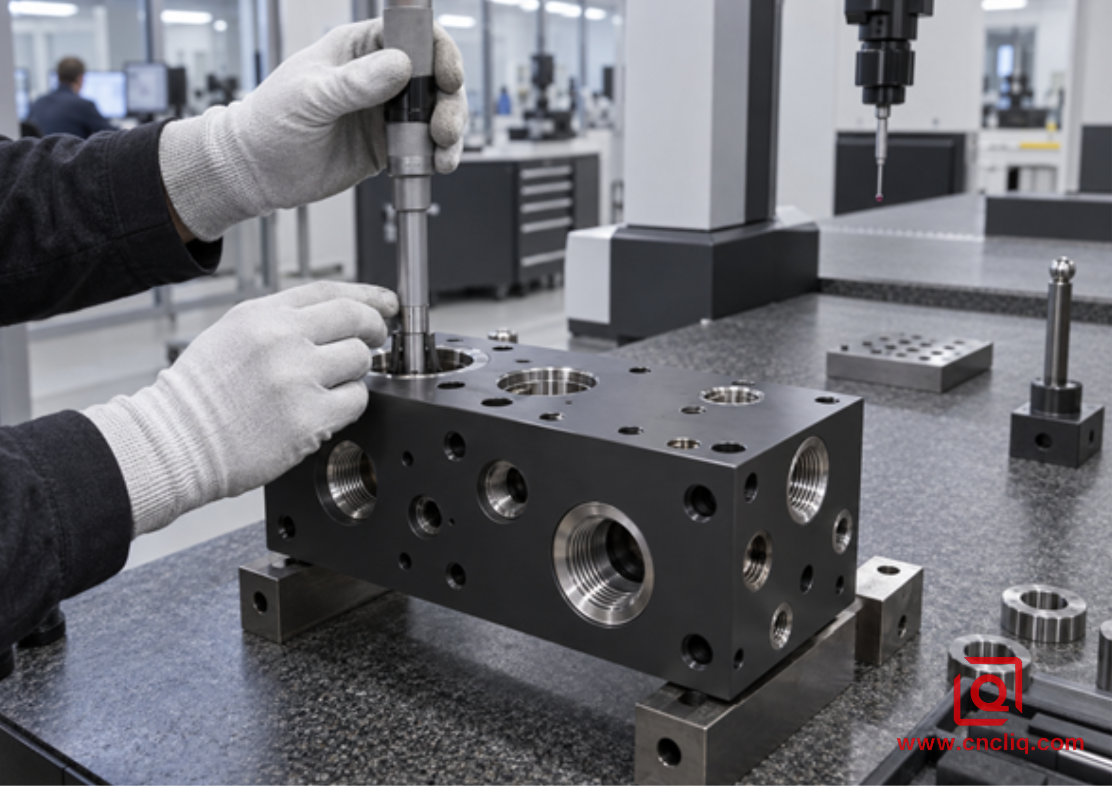
A Type III hydraulic manifold requires post-finish verification of bores, ports, threads, and masked sealing interfaces.
Application guide from the production floor
Electronics and instrument housings usually favor Type II. Their priorities are clean appearance, corrosion protection, electrical insulation, color, and low dimensional impact. Mask grounding pads and connector interfaces. A thin wall can also distort during aggressive pre-treatment or blasting, so appearance preparation must be matched to the geometry. Liqin’s custom aluminum light housing is a relevant product example because enclosure programs combine machining or casting, thermal management, finish appearance, and inspection.
Hydraulic and pneumatic components often justify Type III on wear or fluid-contact surfaces, but not automatically across every feature. Valve-spool lands, sliding guides, and exposed working faces may benefit from hardcoat; precision threads, O-ring sealing lands, and assembly datums may need masking. Liqin’s precision aluminum manifold block shows the kind of multi-port geometry where coating growth, cleanliness, leak testing, and bore control must be planned together.
Robotics and tooling parts need a contact map: a cosmetic cover may use Type II while its guide block uses Type III. Identify load, rubbing, lubrication, and service faces before applying a blanket hardcoat callout.
On an aerospace or medical job, stop at the controlled documents first. The released drawing, validation protocol, and regulatory quality plan outrank a general guide. If a finish touches fatigue, cleanliness, particle control, biocompatibility, grounding, or sterilization, route the change through formal engineering approval.
What to put on the RFQ and drawing
A complete anodizing RFQ lets the machining supplier and finishing source price the same job. Send the 3D model for geometry, but make the 2D drawing control finishing and inspection. Include the following:
Aluminum alloy, temper, material form, and any heat-lot restriction.
Governing standard, anodizing type, class, nominal thickness, and allowed thickness range.
Color requirement, gloss or texture expectation, and approved physical sample when appearance is critical.
Dimensions and tolerances that apply after anodizing, plus any pre-finish reference dimensions.
Masking boundaries for bores, threads, sealing faces, grounding pads, identification areas, and rack-contact zones.
Sealing or post-treatment requirement, including whether abrasion performance or corrosion resistance leads the decision.
Inspection plan: coating thickness method and locations, dimensional checks, appearance sampling, corrosion or abrasion testing, and documentation.
Order quantity, annual demand, first-article quantity, packaging separation, cleanliness, and delivery schedule.
If inputs are unsettled, request DFM review. Liqin’s guide to finishing options for CNC milled aluminum parts compares anodizing with conversion coating, plating, paint, and powder coating. A clear RFQ prevents suppliers from pricing different interpretations.
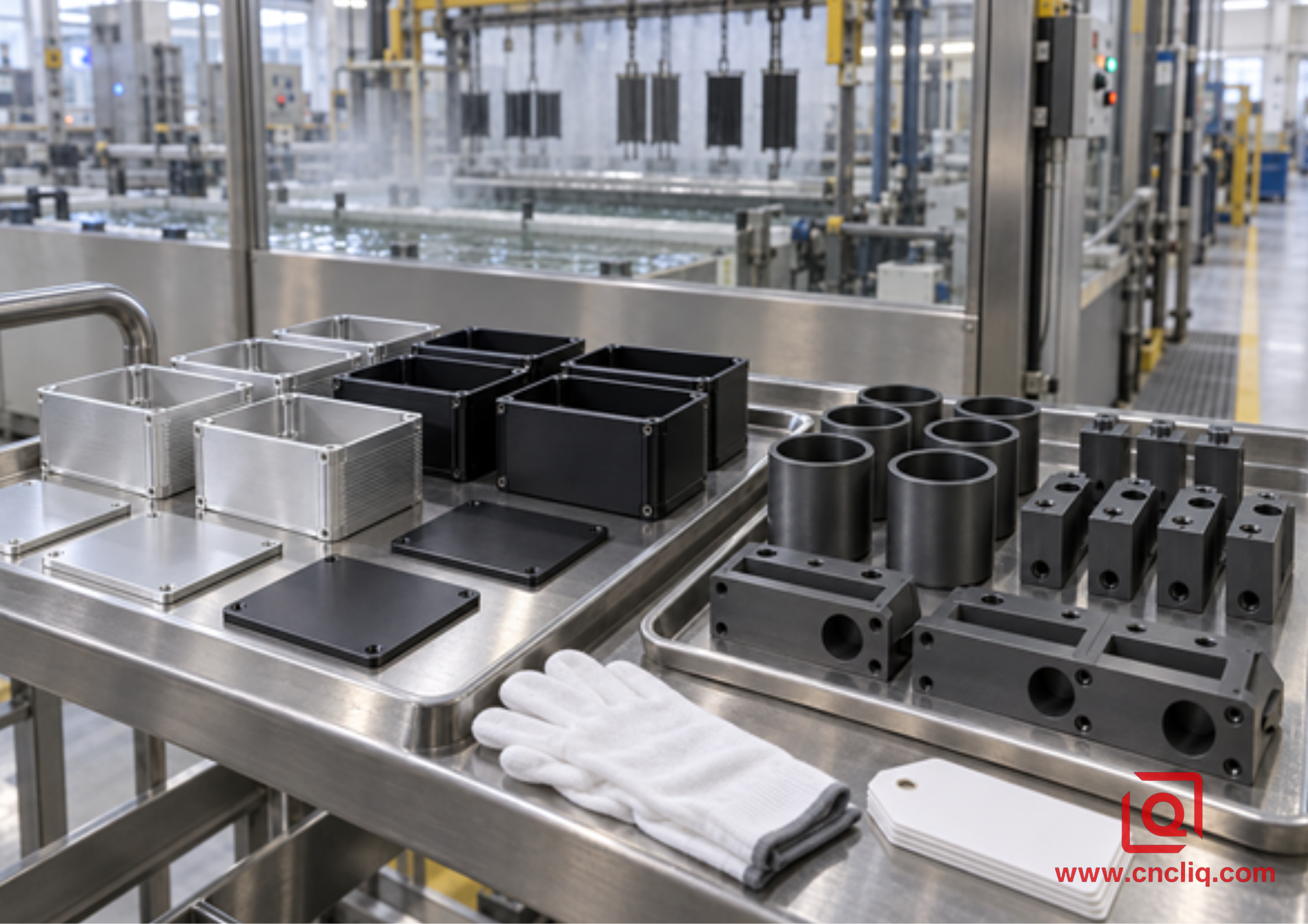
Batch planning separates cosmetic Type II housings from functional Type III components and keeps inspection criteria clear.
How to verify the finished coating
Good anodizing is verified, not assumed from color. For thickness checks, ASTM B244 is the familiar eddy-current route on aluminum, and it does not damage the part. Use suitable calibration standards and defined, accessible locations; edge, corner, thread, and recess readings may not represent the working surface. State the sampling and reportable zones.
Check fit-critical dimensions after finishing. Use CMM for locations and profiles, and suitable bore, air, thread, or functional gauges for individual features. Match the method to the tolerance and surface.
For appearance, define viewing distance, light, orientation, and an acceptance sample. Natural hardcoat shade variation is not automatically a defect, while burns, powder, exposed areas, staining, pitting, or unapproved mismatch require review. Name the corrosion or abrasion standard and pass/fail criteria.
Anonymous customer case: stopping a manifold bore from closing
This anonymized composite illustrates a realistic workflow, not a universal result. An automation buyer requested a black 6061-T6 manifold and wrote “hard anodize all over.” The part had 12 ports, 2 spool bores, an O-ring face, and a grounding pad; the 20.000 mm bore had a 0.018 mm tolerance band.
Review found 3 conflicts: an estimated 0.050 mm bore closure exceeded the tolerance, the O-ring face risked dimensional change, and the grounding pad would become insulating. Only the 2 spool bores truly needed wear resistance.
The body therefore received black Type II, while the 2 wear bores used controlled Type III with first-article allowance. The O-ring land, grounding pad, and selected threads were masked. Machining through final gauging became one process plan.
First-article evidence included thickness readings, finished bore measurements, thread gauges, range-sample inspection, and approved leak testing. The verified routing and rack orientation became the production baseline. Mixed finishing is not always required, but wear, tolerance, and electrical maps must agree before release.
Cost and lead-time factors buyers can control
Type III normally costs more because it needs colder bath control, more time and energy, and closer inspection. Deep recesses, mixed masking, difficult racking, cosmetic faces, and prototype quantities add further setup and handling cost.
Reduce cost by removing ambiguity: standardize alloy and finish where service allows, mask only functional zones, use realistic cosmetic criteria, share annual demand, approve a color range sample, and reserve tight post-anodize tolerances for true interfaces.
Ready for a quote?
Send Liqin your STEP model, controlled drawing, alloy, quantity, service environment, wear points, color, thickness, final dimensions, and mask map. We can review Type II, Type III, selective hardcoat, or another finish. For a comparable quote, identify the 3 features that cannot move and the 3 surfaces doing the hardest work. Contact us directly to discuss the RFQ.
FAQ
1. Does Type III automatically beat Type II?
No. No. Its thicker, more wear-resistant film solves a tougher contact problem; it can also add needless cost and close a careful fit. Put it where sliding, grit, or repeated contact gives the hard layer a job to do. For housings, brackets, trim, and color-coded hardware, Type II is usually the cleaner value because appearance and corrosion protection lead the brief.
2. How much does anodizing change a bore or shaft diameter?
Only the outward portion of the oxide changes the envelope, and the exact penetration-to-build ratio depends on the qualified process. For early planning, engineers often estimate about 50 percent outward growth per surface. Using that estimate, 50 µm of coating moves a complete shaft or bore diameter by roughly 0.050 mm. Confirm the real allowance with the finisher and first-article data.
3. Can Type III hardcoat be black and still keep its wear resistance?
Black Type III is common, but the final shade depends on alloy, coating thickness, dye, and sealing. A dyed or sealed condition may perform differently from an unsealed hardcoat in abrasion service, so color should not be added as an afterthought. Keep these choices together on one controlled note: Class 1 or 2, the seal or post-treatment, a physical range sample, and the wear requirement.
4. Which alloy is the calmer choice for finish consistency?
Start with 6061 when strength permits. Its chemistry and cutting behavior give both Type II and Type III a comparatively steady foundation. 7075 still anodizes well, though it often turns darker or olive; copper-rich 2024 asks more of the qualified process. Cast alloys may show gray or mottled appearance. Always qualify the actual alloy, temper, material form, and heat lot used for production.
5. What lets a supplier quote anodizing without padding for uncertainty?
Send the alloy and temper, CAD, controlled drawing, finish standard, type and class, thickness band, color, seal, final dimensions, mask and rack zones, inspection plan, quantity, and service conditions. If one field is open, mark it open and explain what the surface must do. That lets the supplier recommend a controlled option instead of hiding uncertainty in the price.
Summary
The practical split is this: Type II looks after color and everyday corrosion exposure; Type III takes the rubbing and abrasive work. Review alloy, thickness, dimensional growth, sealing, masking, inspection, and real contact conditions. A complete drawing and RFQ prevent fit, grounding, color, and quotation problems.
Contact Information
Company: Ningbo Liqin Industry Co., Ltd.
Daily customer maintenance & after-sales support:service@shturl. zhuwanying@cncliq.com
New inquiry, quotation & order discussion:business@shturl. zhouli@chinaliqin.com
Hotline: +86 18757148656
Disclaimer
All technical articles, material specifications, machining recommendations, and surface treatment details published on this blog are for informational and reference purposes only. Please note that general blog insights do not replace signed technical agreements. Because custom parts vary by material heat numbers, machine calibrations, and specific tolerances, binding quality specs are governed solely by your approved CAD drawings, signed contracts, and formal quality plans.
All customer case studies featured on this blog have been thoroughly anonymized and sanitized. The performance metrics, manufacturing workflows, and imagery displayed serve solely to demonstrate our custom machining capabilities and do not represent a single universal standard for all orders.
Liqin Manufacturing Team
Built on 18 years of precision engineering experience, Ningbo Liqin Industry manufactures high-tolerance metal components for demanding global markets. We operate out of a 6,500 m² production hub equipped with over 150 machines, running 4-axis and 5-axis CNC machining, mill-turn machining, cold extrusion, and pressure die casting under one roof. This setup allows us to manage projects seamlessly, taking parts from initial CAD concepts directly to finalized shipments.
We handle quality control with zero compromise. We treat tight tolerances with the engineering discipline they require. Backed by ISO 9001, ISO 13485, and IATF 16949 certifications, our QA engineers run strict IPQC, FQC, and OQC checks on every single production batch. From CMM dimensional mapping and optical profiling to hardness and salt-spray testing, we validate your critical specs upfront—so you receive drop-in ready components with zero assembly headaches or costly line stoppages. On top of manufacturing, you can rely on us for two-hour response times on new RFQs, direct support for prototype sampling, and smooth export shipping across Europe, North America, Asia, and Oceania.
Welcome your inquiries and samples. Visit our website or contact us directly for a competitive quote!
