 English




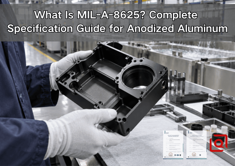
Are you still unsure whether your drawing needs Type II or Type III anodizing, what Class 1 and Class 2 actually mean, or why a perfectly machined bore becomes too tight after finishing? On the shop floor, the issue is rarely the basic anodizing chemistry. Trouble starts when the drawing leaves decisions open. We will begin with the document number, then follow the part through type selection, masking, coating growth, inspection, and final assembly.
Start with the name in the title block. MIL-A-8625 is the familiar legacy designation. The active document is MIL-PRF-8625F with Amendment 2, dated November 23, 2020. Check the DLA ASSIST entry and you will see its status marked active. The scope covers 6 anodic-coating types and 2 classes for non-architectural aluminum and aluminum-alloy parts. Engineers still say “MIL-A-8625” because the old designation remains on legacy drawings, supplier websites, and search queries. For a new order, however, the purchase document should identify the required revision or state that the latest revision applies. In other words, a print that says only “black anodize” still leaves too many choices to the processor.
Start Here: What Does the Specification Control?
At its core, the document sets performance requirements for an oxide grown electrolytically from an aluminum surface. It classifies coatings by process family and by whether the coating is dyed. It also sets requirements for workmanship, coating mass or thickness, corrosion resistance, lightfastness where applicable, paint adhesion when required, abrasion resistance for Type III, sampling, process control, and test methods.
This is a performance document, not a one-recipe process sheet. A 6061 bracket and a high-silicon casting do not behave the same way in a tank. The drawing therefore defines the result; the approved processor chooses and controls the chemistry, current, temperature, pretreatment, racking, dye cycle, and seal needed to reach it.
|
Item |
What it means for the buyer |
What must be decided |
|
Type |
The anodizing process family and intended performance |
Type I, IB, IC, II, IIB, or III |
|
Class |
Whether the anodic coating is dyed |
Class 1 is non-dyed; Class 2 is dyed |
|
Color |
A visual requirement, not a substitute for class |
State the required color and any approved range |
|
Thickness or coating mass |
Controls protection, wear behavior, and dimensional change |
State the target and tolerance where function requires it |
|
Sealing |
Changes corrosion, dye retention, wear, and friction behavior |
State sealing requirements, especially for Type III |
|
Masking and contact points |
Preserves threads, bores, electrical bonds, and cosmetic faces |
Mark exact keep-out zones and permitted rack locations |
|
Acceptance tests |
Defines objective evidence of conformance |
Identify certificates, reports, sampling, and special tests |
For a broader comparison with conversion coating and powder coating, see Liqin’s aluminum OEM surface finishing guide. This article stays focused on interpreting the military anodizing specification rather than repeating that finish-selection overview.
Why Do Drawings Use Both MIL-A-8625 and MIL-PRF-8625?
The two names come from the document history, not from two competing finishes. MIL-A-8625F was redesignated MIL-PRF-8625F; Amendment 2 superseded MIL-A-8625F with Amendment 1. Old prints still carry the earlier prefix. New sourcing work should be checked against the active record before the purchase order is released. The DLA ASSIST record for MIL-PRF-8625 is the controlling place to verify status and revision before release.
Do not silently rewrite a customer’s legacy drawing. Send a technical query and keep the answer with the job record. Ask 3 direct questions: must the old qualification basis remain, may the latest revision be used, and does a customer process specification sit above it? On aerospace and defense work, an approved-processor list or first-article plan may matter just as much as the military document.
How the 6 Anodizing Types Behave on Real Parts
Type I: The Conventional Chromic Route
Type I uses a chromic-acid bath. Its thin oxide is useful where corrosion protection, paint bonding, and fatigue-sensitive geometry matter more than a heavy wear layer. There is a catch: the chemistry contains hexavalent chromium. Review the customer restriction, environmental controls, and worker-safety route before quoting. A non-chromate process may look attractive, but it is not an automatic substitute.
Type IB: Chromic Anodizing at Lower Voltage
Type IB stays in the chromic family, although the specified process runs at 22 ± 2 V. That separate label is meaningful. When a print says Type IB, the traveler, processor approval, and certificate should not quietly say Type I.
Type IC: Non-Chromic Alternative to Type I and IB
Type IC covers non-chromic anodizing intended as an alternative to Type I and IB. Boric-sulfuric anodizing is a familiar example, but “Type IC” is not permission to use any environmentally friendly bath. The chosen process still has to satisfy the contract, the performance requirements, and any program-specific approval.
Type II: Conventional Sulfuric Acid Anodizing
Type II is conventional sulfuric acid anodizing. It is widely chosen for machined housings, brackets, panels, and other parts that need corrosion protection, electrical insulation, or a dyed cosmetic finish without the heavy build of hardcoat. The current specification sets an unsealed coating-mass minimum of 1000 mg/ft² for Type II; the purchase document or drawing should state thickness when thickness is functionally important.
Type II is often the sensible starting point for a colored CNC component, but alloy, temper, surface finish, and material lot affect the final appearance. “Class 2 black” controls the fact that the coating is dyed black; it does not guarantee a universal gloss or a perfect color match between 6061, 7075, and high-silicon cast aluminum.
Type IIB: Thin Sulfuric Acid Anodizing
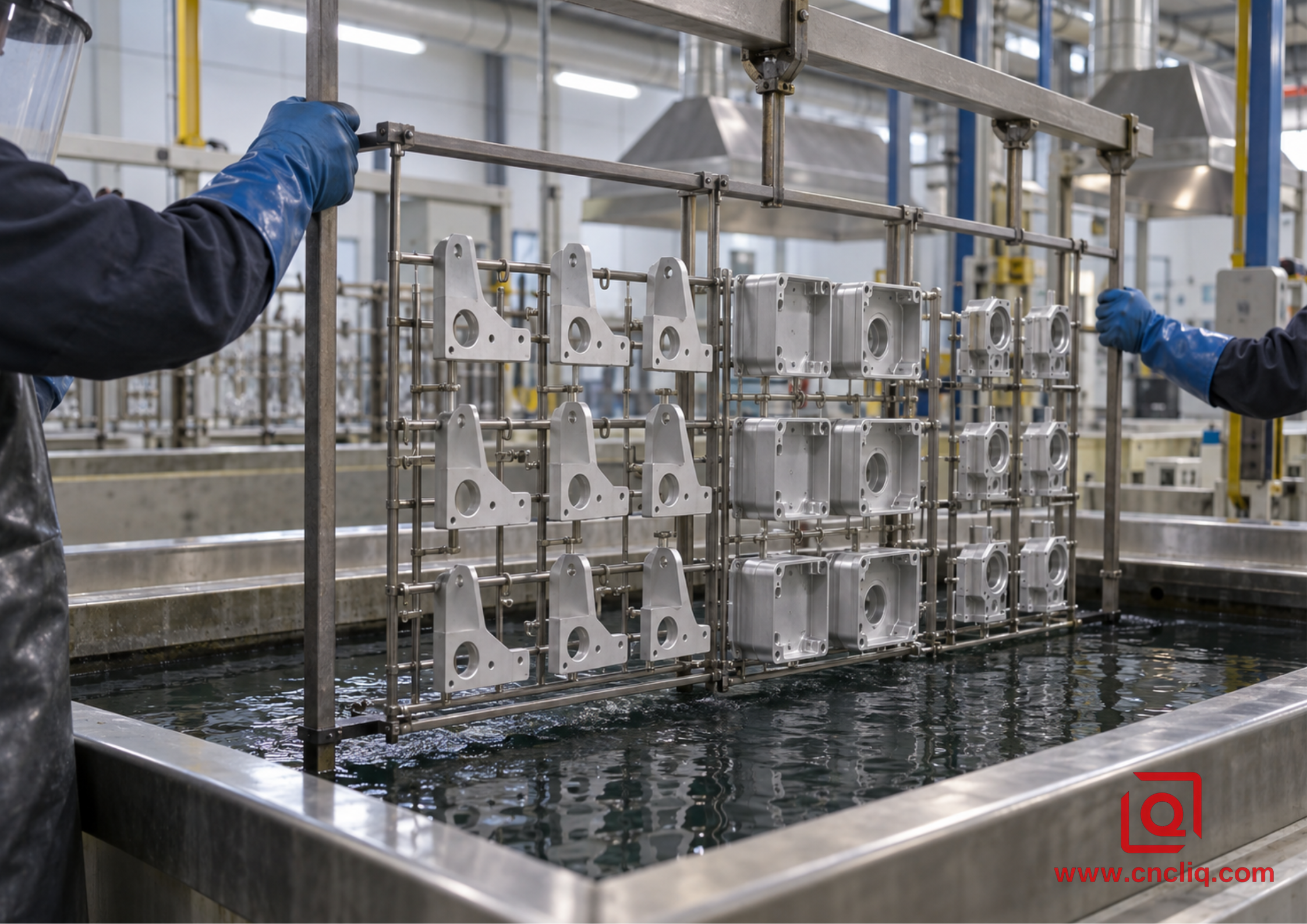
Type IIB is a thin sulfuric acid anodize intended as a non-chromate alternative to Type I and IB. The current standard lists an unsealed coating-mass range of 200 to 1000 mg/ft². It can help where corrosion protection and paint adhesion are needed with less dimensional impact than a conventional decorative sulfuric coating. That does not make dimensions automatic: etching, desmutting, coating growth, alloy response, and measurement method still need to be included in the tolerance plan.
Type III: Hard Anodic Coating
Type III is hard anodizing for wear-resistant service. It is the usual choice for sliding components, hydraulic or pneumatic hardware, guides, valve bodies, and other surfaces that need a dense oxide layer. The coating thickness must be specified by the purchaser. Under MIL-PRF-8625F, thickness variation is generally limited to ±20% for coatings up to 0.002 in, while coatings over 0.002 in have a stated variation limit of ±0.0004 in. If coating mass is accepted instead of thickness, unsealed Type III has a minimum of 4320 mg/ft² for each 0.001 in of coating.
Hardcoat is not automatically the “best” anodize. More thickness can close bores, tighten threads, round sharp visual transitions, make color control harder, and change fatigue performance. Sealing can improve corrosion behavior but may reduce abrasion performance, so the specification does not treat every Type III part as automatically sealed. If wear, corrosion, or dye retention drives the design, say which outcome has priority.
For deeper calculations on growth and tolerance planning, use the related Type III hardcoat anodizing DFM guide. It complements this specification guide with dimensional design detail.
Class 1 vs. Class 2: A Simple Distinction With Big Consequences
Under MIL-PRF-8625, Class 1 means non-dyed and Class 2 means dyed. “Clear anodize” is normally specified as Class 1, but clear does not mean optically colorless. The natural oxide and the alloying elements can produce silver, gray, bronze, or olive shifts. Type III Class 1 is commonly gray to dark gray and may vary across alloys and material lots.
Class 2 requires the color to be stated. A useful drawing note names the color and points to an approved physical sample, color range, or measurable criterion when appearance is critical. Dye name alone is weak acceptance language. A color shift may come from the alloy lot, the blast or etch, oxide thickness, the seal, or even the inspection light—not simply from the dye tank.
For assemblies with multiple visible parts, control these variables early:
• Use the same aluminum alloy and temper.
• Machine visible parts to a consistent surface roughness and toolpath strategy.
• Process matching parts in the same qualified load where practical.
• Define which faces are cosmetic and which contact marks are acceptable.
• Approve a boundary sample instead of relying only on a screen image or a color word.
What Performance Does the Specification Actually Verify?
MIL-PRF-8625 is more rigorous than a finish name because it links the coating to testable requirements. The exact inspection plan depends on type, class, purchase documents, and whether production parts or representative panels are suitable.
Coating Weight and Thickness
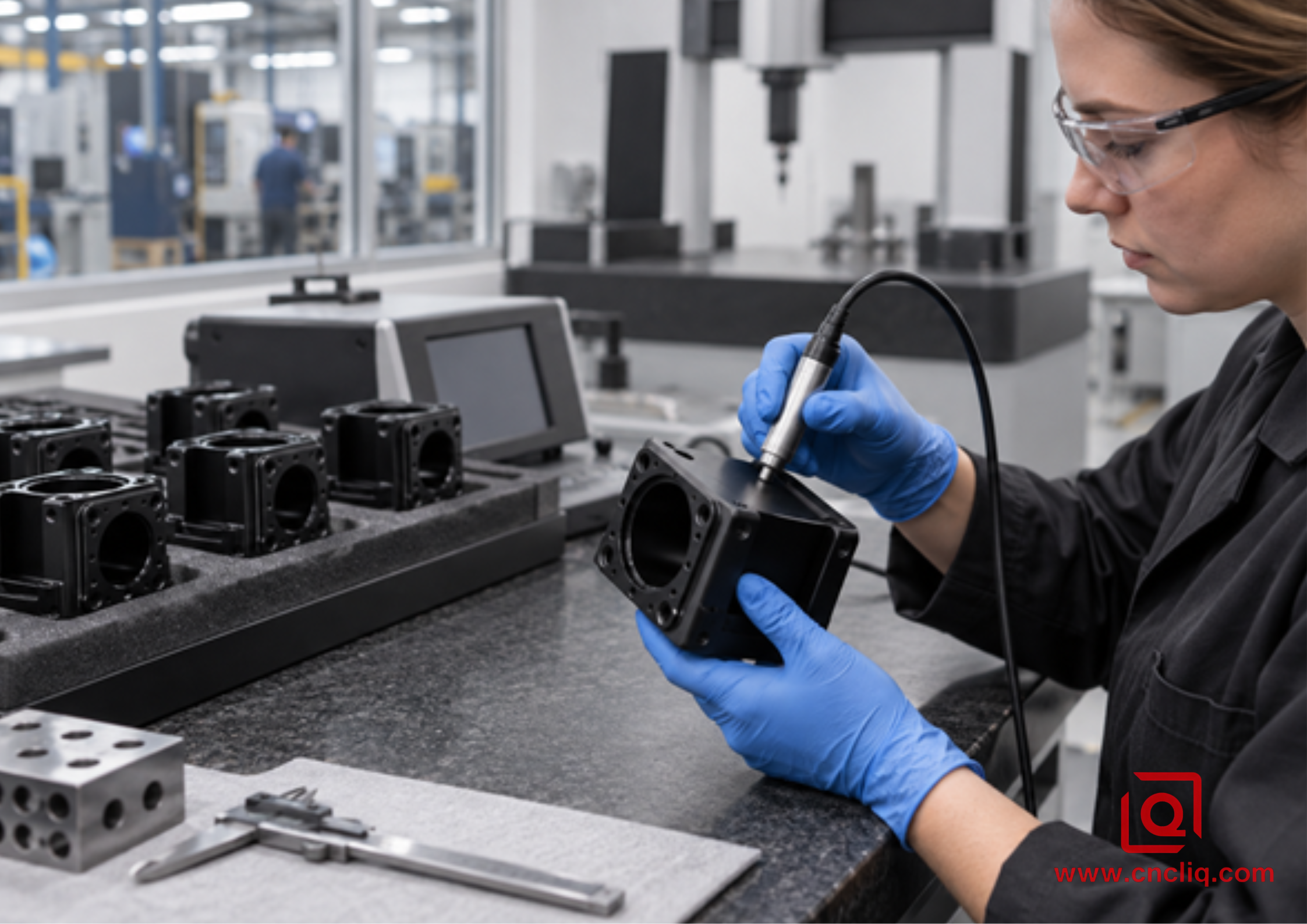
Types I, IB, IC, II, and IIB are controlled by unsealed coating mass in the base requirements. Type III is normally controlled by thickness, with coating mass available at the procuring activity’s option. Thickness can be checked with a suitable eddy-current method when geometry and calibration allow; cross-section methods may be required for correlation or dispute resolution. On a small bore, sharp edge, blind pocket, or contact area, probe access and electrical-current distribution can make the local reading different from an easy, flat witness panel.
Corrosion Resistance
The standard’s corrosion test uses 5% salt spray in accordance with ASTM B117, with the significant surface inclined 6° from vertical for 336 hours. Acceptance is based on isolated pits: across 150 in² from at least 5 specimens, no more than 15 isolated pits are allowed, and no individual pit may exceed 0.031 in; a 30 in² area is limited to 5 isolated pits under the stated exclusions. Type III corrosion testing applies when the coating is sealed and the procuring activity specifies it.
Lightfastness and Paint Adhesion
For dyed Class 2 coatings, lightfastness may be evaluated using the referenced ultraviolet exposure methods and color difference measurement. The current document describes 200 hours of continuous light exposure without water spray. Where anodize is a paint base, wet-tape adhesion testing can be required. If either property matters, place it in the purchase requirements rather than assuming the supplier will infer it from the color.
Type III Abrasion Resistance
For the abrasion check, the lab follows ASTM D4060: CS-17 wheels, a 1000 g load, 70 rpm, and 10000 cycles. Those test settings belong in the report review; “very hard” does not. The wear index is determined from mass loss. This is much more useful than a vague promise that a part is “scratchproof.” Even a compliant hardcoat can be damaged by edge impact, abrasive contamination, poor counterface design, or an unsuitable lubricant.
How Anodizing Changes CNC Part Dimensions
Anodizing converts the aluminum surface rather than simply laying a separate film on top. Part of the oxide grows into the substrate and part grows outward. A common early-estimating rule for sulfuric anodizing is roughly half penetration and half outward growth, but it is not a universal acceptance formula. Treat the half-in, half-out idea as a sizing estimate. The real result still follows the alloy, etch, bath, coating type, current path, and part geometry.
Take a 10.000 mm bore as a quick check. With a 0.020 mm oxide and an estimated 0.010 mm outward build on each wall, the opening may finish near 9.980 mm. That is enough to stop a close dowel, bearing, or valve spool from assembling. The correct response is not to hope the anodizer “holds the bore.” Decide whether to pre-compensate, mask, plug, post-machine, or relax the fit based on function.
Threads require the same discipline. Coating on both flanks consumes clearance, while masking leaves bare aluminum that may need another protection strategy. Blind holes can trap solution if drainage and rinsing are poor. Sharp corners can carry thin or brittle oxide and are more vulnerable to chipping. A small radius or controlled edge break usually gives a more stable finish than a knife edge.
Liqin’s guide to high-precision aluminum machining and anodizing allowances covers the machining side of this handoff. If the material is not settled, compare 6061, 7075, and 5052 in Liqin’s aluminum machining guide. The choice changes both the cutter strategy and what comes out of the anodizing tank.
A Drawing Callout That a Supplier Can Actually Use
A strong callout removes choices that affect fit, appearance, and validation. A practical format is:
ANODIZE PER MIL-PRF-8625F, TYPE II, CLASS 2, BLACK; 0.010–0.018 mm COATING THICKNESS; SEAL; MASK ALL M6 THREADS, Ø8 H7 BORES, AND IDENTIFIED GROUNDING PADS; RACKING CONTACT PERMITTED ONLY ON SURFACE A; FINAL DIMENSIONS APPLY AFTER FINISH UNLESS OTHERWISE MARKED.
That is an example, not a universal prescription. Change the type, revision, thickness, seal, color, mask, rack location, and dimensional basis to match the design. If a legacy contract requires MIL-A-8625F, do not change it without approval.
Before issuing the drawing, answer 8 questions:
1. Which revision controls the order?
2. Which type and class are required?
3. What alloy and temper will be supplied?
4. Is thickness, coating mass, or both functionally controlled?
5. Are dimensions before or after anodizing?
6. Which surfaces must be masked, plugged, conductive, or cosmetic?
7. Is Type III sealed, unsealed, dyed, lubricated, or otherwise post-treated?
8. Which certificates, inspection reports, and test results must ship with the batch?
If your print contains close fits or multiple secondary processes, send the STEP model and 2D drawing together. A CNC machining supplier with integrated DFM review can flag finish conflicts before material is cut.
Shop-Floor Controls That Prevent Expensive Rejections
Start With Incoming Material Traceability
The finisher cannot make mixed alloys look identical. Material certification, alloy, temper, and lot traceability matter when mechanical performance or color consistency is controlled. Cast surfaces, welds, filler metal, copper-rich areas, and repaired defects can respond differently in the same bath.
Stabilize the Pre-Anodize Surface
Anodizing follows the surface underneath it. Deep cutter marks, hand-polished patches, bead-blast overlap, embedded media, and uneven etching can remain visible after dyeing. Define the required surface roughness or approved visual sample before anodizing, not after the first batch is rejected. Liqin’s machinist’s guide to aluminum surface finishes shows how pretreatment and machining texture interact.
Design Masking and Racking Into the Part
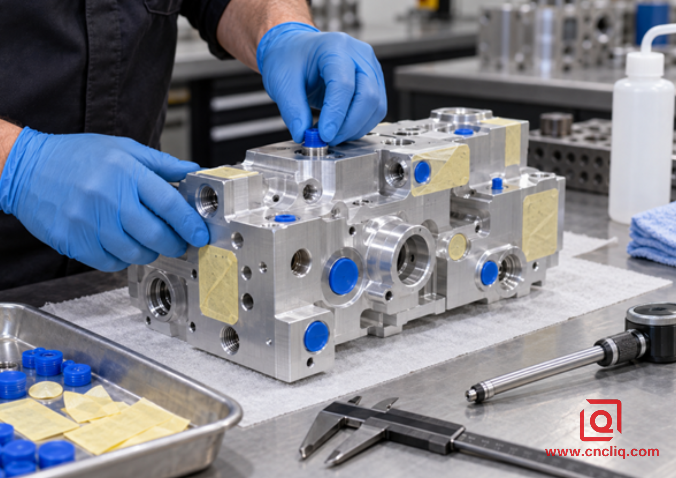
Every anodized part needs electrical contact. That contact leaves a local uncoated mark. Put it on a hidden, nonfunctional, approved location. Threads and bores can be protected with plugs; flat grounding areas often need die-cut masking. Complex internal passages require drainage, rinsing, and air-release planning. Mark these zones in the CAD and drawing so the masking operator does not have to interpret a screenshot.
Inspect the Finished Requirement, Not Just a Flat Coupon
A witness panel helps prove process control, but the production part still carries functional risk. Check critical post-finish bores, thread gauges, sealing faces, electrical bond areas, color boundaries, burns, powdery residue, contact marks, and coating damage. Use calibrated methods appropriate to the feature. Record nonconforming locations rather than reporting one convenient thickness value from the broadest face.
Anonymous Composite Case: Hard-Anodized Aluminum Manifold
The following is an anonymized composite example created to show a realistic workflow; it does not identify a single customer or promise the same result for every order.
An industrial automation buyer needed a custom 6061-T6 pneumatic manifold with crossed passages, M6 ports, an 8 mm locating bore, and an exposed sliding face. The original note read only “black hard anodize.” That wording left the processor to guess the governing revision, class, thickness, sealing condition, masking boundaries, and whether the locating bore was a finished dimension.
During DFM review, the team separated the functions. The exterior and sliding face required Type III Class 2 black at a purchaser-approved thickness. The locating bore had to remain within its assembly fit after finishing. Valve-seat faces and selected threads could not tolerate coating buildup. One hidden boss was assigned as the rack-contact location. The revised drawing marked all masks and stated that critical dimensions applied after anodizing.
The process route became: certified 6061-T6 stock, rough machining, stress stabilization where required by the part plan, finish machining with controlled allowance, complete deburring, aqueous cleaning, masking and plugging, hard anodizing, dyeing and the specified post-treatment, demasking, channel cleaning, coating-thickness verification on accessible production surfaces, thread and bore gauging, CMM inspection of critical datums, and final visual review under agreed lighting.
For a product example that uses closely related geometry and finish decisions, see Liqin’s custom CNC-machined anodized aluminum manifold. The lesson is simple: a coating callout must be connected to the part’s fit, fluid path, electrical needs, and inspection plan. “Hard anodize black” alone cannot do that job.
How to Choose Type II or Type III for an RFQ
|
Decision factor |
Type II is often suitable when… |
Type III is often suitable when… |
|
Primary goal |
Corrosion protection, color, general handling resistance |
Wear, abrasion, sliding contact, heavy service |
|
Typical part |
Housing, bracket, panel, cosmetic CNC component |
Valve body, guide, rail, piston-related hardware |
|
Appearance |
Broader dye-color options and easier cosmetic control |
Usually darker, more thickness-dependent appearance |
|
Dimensional risk |
Moderate, still important on fits and threads |
Higher because the specified layer is commonly thicker |
|
Sealing decision |
Commonly sealed for corrosion and dye retention |
Must be chosen around wear and corrosion priorities |
|
Cost driver |
Color matching, masking, low quantity, cosmetic rejection |
Thickness, bath time, cooling, masking, testing, grinding or honing after finish |
Do not select by price alone. The low quote is not always the low-cost route. Type II can wear through in the wrong contact pair; Type III can turn a simple cosmetic cover into a tolerance problem. A useful quote needs the production picture: annual demand, release quantity, part size, alloy, finish callout, masks, visual limit, test paperwork, and packing method.
What to Send With the RFQ
Put these items in the first inquiry, not in a follow-up after pricing:
• 3D CAD model and controlled 2D drawing revision.
• Aluminum alloy, temper, material form, and certification requirement.
• Exact specification designation and revision.
• Anodizing type, class, color, thickness, and sealing condition.
• Before-finish and after-finish dimensional requirements.
• Masking map, conductive areas, plugged threads, and allowed rack marks.
• Cosmetic zones, surface finish, color sample, and viewing criteria.
• Required FAI, CMM report, coating certificate, thickness map, salt-spray evidence, or other test reports.
• Prototype quantity, production quantity, target delivery, and packaging restrictions.
If you are choosing between 3-axis, 5-axis, and mill-turn production before anodizing, the custom aluminum OEM process-selection guide helps match geometry to the manufacturing route. When the machinist and finisher review the same drawing early, fewer dimensions need to be negotiated after parts are already cut.
FAQ
1. Why is MIL-A-8625 still printed on current parts?
Thousands of controlled legacy drawings still use MIL-A-8625, so the name has not disappeared from factories. DLA ASSIST, however, lists MIL-PRF-8625F Amendment 2, dated November 23, 2020, as active. Check the record on new work. On a legacy program, get written approval before changing the note or its qualification basis.
2. Does Class 1 mean clear and Class 2 mean black?
No. The class tells you whether dye is used: Class 1 is non-dyed and Class 2 is dyed. Black is merely one Class 2 choice. A Class 1 part may still appear silver, gray, bronze, or olive, so a cosmetic limit needs more than the class number.
3. Can the drawing omit anodize thickness?
Do not leave it open when fit or wear depends on the oxide. The purchaser must state Type III thickness, and the Aluminum Anodizers Council advises putting Type II thickness on the drawing or purchase document. Choose the value around the job; copying one house number onto every part creates avoidable fit problems.
4. Should Type III hardcoat be sealed?
Not automatically. Sealing can improve corrosion performance and dye retention, but it may reduce abrasion performance. State the required condition based on the service environment, wear pair, lubricant, color, and acceptance tests; if the drawing is silent, resolve it during contract review.
5. What information gives the fastest reliable anodizing quote?
Provide the alloy and temper, STEP model, controlled 2D drawing, specification revision, type, class, color, thickness, sealing, masks, cosmetic requirements, critical post-finish dimensions, test documentation, batch size, and annual demand. That package lets the manufacturer quote machining allowance, racking, inspection, and finishing as one controlled route instead of adding risk after machining.
Summary
The shop may still call it MIL-A-8625, while the active document is MIL-PRF-8625F Amendment 2. A reliable order identifies the correct type and class, states thickness and sealing where required, controls masking and rack marks, defines whether dimensions apply before or after finishing, and names the evidence needed for acceptance. Treat anodizing as part of the dimensional and functional design—not as a color added after machining—and your aluminum parts are far more likely to arrive ready for assembly.
Contact Information
Company: Ningbo Liqin Industry Co., Ltd.
Daily customer maintenance & after-sales support:service@shturl. zhuwanying@cncliq.com
New inquiry, quotation & order discussion:business@shturl. zhouli@chinaliqin.com
Hotline: +86 18757148656
Disclaimer
All technical articles, material specifications, machining recommendations, and surface treatment details published on this blog are for informational and reference purposes only. Please note that general blog insights do not replace signed technical agreements. Because custom parts vary by material heat numbers, machine calibrations, and specific tolerances, binding quality specs are governed solely by your approved CAD drawings, signed contracts, and formal quality plans.
All customer case studies featured on this blog have been thoroughly anonymized and sanitized. The performance metrics, manufacturing workflows, and imagery displayed serve solely to demonstrate our custom machining capabilities and do not represent a single universal standard for all orders.
Liqin Manufacturing Team
Built on 18 years of precision engineering experience, Ningbo Liqin Industry manufactures high-tolerance metal components for demanding global markets. We operate out of a 6,500 m² production hub equipped with over 150 machines, running 4-axis and 5-axis CNC machining, mill-turn machining, cold extrusion, and pressure die casting under one roof. This setup allows us to manage projects seamlessly, taking parts from initial CAD concepts directly to finalized shipments.
We handle quality control with zero compromise. We treat tight tolerances with the engineering discipline they require. Backed by ISO 9001, ISO 13485, and IATF 16949 certifications, our QA engineers run strict IPQC, FQC, and OQC checks on every single production batch. From CMM dimensional mapping and optical profiling to hardness and salt-spray testing, we validate your critical specs upfront—so you receive drop-in ready components with zero assembly headaches or costly line stoppages. On top of manufacturing, you can rely on us for two-hour response times on new RFQs, direct support for prototype sampling, and smooth export shipping across Europe, North America, Asia, and Oceania.
Welcome your inquiries and samples. Visit our website or contact us directly for a competitive quote!
