 English




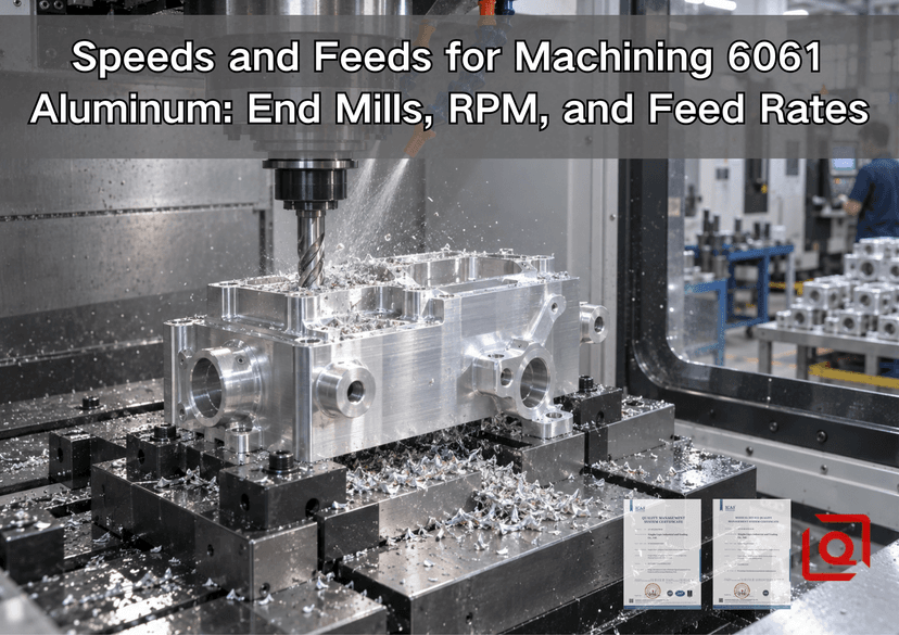
Are you wrestling with aluminum welded onto a cutter, an unexplained squeal, snapped end mills, or a finish that looks different every time 6061 returns to the vise? Keep reading. We will work from a cautious first setting to a proven shop number, and we will show the arithmetic along the way. This is written for the person at the machine and the engineer buying the part; both need a stable process, not a heroic figure lifted from a chart.
6061 is friendly to machine, but it is not automatic. A high spindle speed paired with a timid feed can make the tool rub. A sensible feed with poor chip evacuation can pack a slot in seconds. Long tool stickout, weak workholding, a full-width cut, or a short toolpath that never reaches the commanded feed can turn a sound parameter set into scrap. That is why every number below is a starting point tied to stated assumptions. Your cutter manufacturer's data and a controlled first-cut trial should take priority.
Quick Answer: A Practical Starting Window for 6061
For a rigid vertical machining center, a sharp carbide end mill made for aluminum, secure workholding, and effective air blast, mist, or flood coolant, a conservative general starting window is:
|
Parameter |
Practical starting point |
What it controls |
|
Cutting speed, Vc |
200–500 m/min |
Edge speed and heat generation |
|
Carbide baseline when the setup is unknown |
300 m/min |
A useful calculation point, not a guaranteed optimum |
|
Chip load, fz |
0.03–0.10 mm/tooth |
Chip thickness, cutting action, and edge load |
|
Flute count |
2 for tight slots; 3 for general profiling |
Chip space versus productivity |
|
Radial engagement, ae |
10%–30% of cutter diameter for initial side milling |
Tool load and chip thickness |
|
Full-slot feed adjustment |
Begin at 50%–70% of a proven side-milling feed |
Extra load and restricted chip escape |
|
Finish allowance |
0.20–0.50 mm per side when geometry allows |
Stable finishing load and dimensional correction |
Do not copy this table straight into production. Small cutters, thin walls, extended-reach tools, desktop routers, low-torque spindles, and full slotting need lower loads. A tool supplier's value for the exact catalog number is more valuable than a broad material range. RobbJack, for example, publishes diameter-specific data for its own 2-flute 6061 tools, while Harvey Performance shows how two cutters of the same diameter can require different chip loads because their geometries differ.
Why 6061 Still Produces Bad Cuts
Walk through almost any general CNC shop and 6061-T6 or T651 will turn up in a housing, fixture plate, bracket, or fluid block. Its popularity is no mystery. The alloy is reasonably strong, light, readily available, corrosion tolerant, and usually pleasant to cut and anodize. Still choosing the stock? Our comparison of 6061, 7075, and 5052 for custom CNC milling sets those trade-offs against the job the part must actually do.
The usual failure is not simply “too much RPM.” It is a mismatch between speed, chip load, engagement, chip clearance, and rigidity. Aluminum can adhere to a hot cutting edge and create built-up edge. The effective geometry then changes: the edge stops shearing cleanly, cutting force rises, the wall finish smears, and the tool may chip or snap. In a deep pocket, recutting hot chips makes the cycle less stable even when the programmed RPM and feed are reasonable.
There is another practical issue. The programmed feed is not always the feed achieved at the cutting edge. Short line segments, sharp corners, small arcs, and conservative machine acceleration can keep the axis below the commanded rate. RPM stays high while actual chip load falls. The tool rubs exactly where the geometry becomes most critical. Looking only at the CAM summary can therefore hide the real cause.
The 3 Formulas That Matter
The standard milling relationships are simple. Sandvik Coromant publishes the metric definitions below, and Kennametal presents the same relationship in inch units.
Spindle speed:
RPM = (Vc × 1000) ÷ (π × D)
Table feed:
Feed rate (mm/min) = RPM × z × fz
Metal removal rate:
MRR (cm³/min) = ap × ae × feed rate ÷ 1000
Where Vc is cutting speed in m/min, D is effective cutter diameter in mm, z is the number of effective flutes, fz is feed per tooth in mm, ap is axial depth of cut in mm, and ae is radial engagement in mm. In inch units, RPM = (SFM × 3.82) ÷ tool diameter, and IPM = RPM × flute count × IPT.
The order matters. Choose a defensible cutting speed for the exact tool and operation. Convert it to RPM. Check the machine's spindle limit. Then calculate feed from chip load. When the spindle tops out below the calculated speed, accept the RPM you truly have, then run the feed calculation again. Otherwise the chip load has changed even though nobody intended to change it.
Worked Example: 10 mm, 3-Flute Carbide End Mill
Here is a first pass I would be comfortable supervising at the machine: a rigid setup, a short 10 mm aluminum cutter with 3 flutes, 30% radial engagement, 300 m/min surface speed, and 0.06 mm per tooth.
RPM = (300 × 1000) ÷ (π × 10) = 9,549 RPM
Feed = 9,549 × 3 × 0.06 = 1,719 mm/min
If axial depth is 5 mm and radial engagement is 3 mm:
MRR = 5 × 3 × 1,719 ÷ 1000 = 25.8 cm³/min
That answer gets us to the machine door; it does not release the job. I would still look at the holder, the length hanging out, the way the fixture sits, available power near 9,549 RPM, nozzle aim, pocket depth, wall support, and every place the path briefly becomes a full-width cut. Begin under supervision, watch the chip and listen. Change one thing, then look again.
Metric Starting Candidates by End-Mill Diameter
For the table below I held surface speed at 300 m/min, chose a 3-flute carbide tool, and changed chip load with diameter. Think of each row as a ticket for a supervised side-milling trial on a capable machine. None is permission to press cycle start on an unattended batch.
|
Cutter diameter |
Chip load |
Calculated RPM |
Calculated feed |
First checks before increasing load |
|
3 mm |
0.02 mm/tooth |
31,831 RPM |
1,910 mm/min |
Spindle limit, runout, fragile edge, chip evacuation |
|
6 mm |
0.04 mm/tooth |
15,915 RPM |
1,910 mm/min |
Stickout, corner deceleration, pocket depth |
|
8 mm |
0.05 mm/tooth |
11,937 RPM |
1,791 mm/min |
Holder rigidity, radial engagement, coolant aim |
|
10 mm |
0.06 mm/tooth |
9,549 RPM |
1,719 mm/min |
Spindle load, wall stiffness, entry method |
|
12 mm |
0.07 mm/tooth |
7,958 RPM |
1,671 mm/min |
Torque, fixture support, toolpath consistency |
If a 3 mm tool is used on a 12,000 RPM spindle, do not keep 1,910 mm/min. Preserve 0.02 mm/tooth by recalculating: 12,000 × 3 × 0.02 = 720 mm/min. This is the habit that prevents a speed-limit adjustment from silently changing the cutting action.
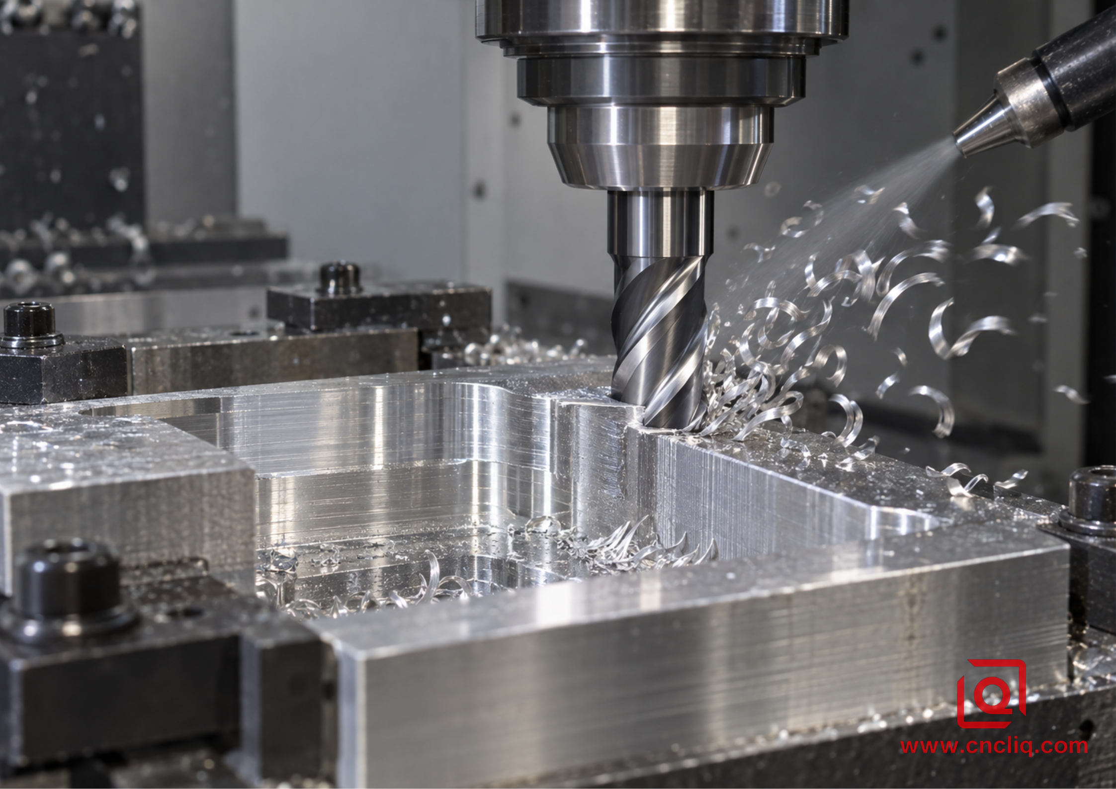
A polished end mill cutting a 6061 aluminum pocket
Choosing the Right End Mill
2 Flutes or 3 Flutes?
Two flutes leave a great deal of room for the chip. I reach for that shape first in a full slot, a deep pocket, a small spindle, or any setup where the air barely reaches the bottom. Three flutes trade away some space and gain another working edge. On a stiff production mill, that is often the useful middle ground for profiles and adaptive roughing; a general-purpose 4-flute tool is not automatically an upgrade.
More flutes do not automatically mean faster production. Feed rises with flute count only if each flute can form and evacuate its chip. When chips pack between the tool and wall, the extra edge becomes a liability. Choose flute count from the engagement and evacuation path, not from the maximum feed shown in CAM.
Geometry, Edge Preparation, and Coating
Look for a sharp positive rake, polished flutes, and geometry designed for nonferrous materials. Uncoated polished carbide is widely used because a keen edge and smooth flute help resist aluminum adhesion. Some purpose-built coatings for nonferrous machining can also work well, but do not assume that a coating successful in steel belongs in aluminum. Follow the tool maker's application data for the exact series.
Runout becomes painfully visible as the tool and chip get smaller. Picture 0.01 mm total indicated runout beside a programmed 0.02 mm chip: one edge may be doing most of the work while its neighbors merely polish. Clean the taper and collet, shorten the reach to what the feature needs, and retire a damaged holder before trying to program around it.
Tool Diameter and Reach
Use the largest diameter that can reach the feature with adequate corner clearance. A larger tool is normally stiffer and offers more flute volume. But do not select a long-reach cutter merely because it can machine every feature. Separate roughing, rest machining, and detail tools often produce a faster and more reliable process. Complex access may justify multi-axis CNC milling, which can shorten effective reach and reduce refixturing.
Adjust Parameters for the Actual Operation
Side Milling and Adaptive Roughing
Low radial engagement gives chips room to leave and keeps tool load more consistent. It can support a deeper axial cut, but radial chip thinning becomes relevant when engagement is small. The programmed feed per tooth may need correction to maintain the desired maximum chip thickness. Use the CAM system's verified chip-thinning model or the cutter manufacturer's calculator rather than guessing.
Smooth helical entries and constant-engagement paths are preferable to sudden full-width plunges. Avoid pausing in the cut. If a pocket has narrow regions where engagement rises, apply local feed control or use rest machining so the tool does not encounter an unexpected material wedge.
Full Slotting
Slotting surrounds the cutter with material on both sides. Load rises, chips have less escape space, and coolant access becomes harder. Begin at 50%–70% of a proven side-milling feed, keep axial depth conservative, and favor 2 flutes where clearance is tight. Do not solve packed chips by reducing feed alone; that can create thinner, hotter chips. Improve evacuation or reduce engagement first.
Finishing Walls and Floors
A finish pass should remove a consistent allowance. Leaving almost nothing can make the edge rub across areas where the roughing pass already flexed away. Leaving too much repeats the roughing load and deflection. A 0.20–0.50 mm radial allowance is a practical planning range for many medium-sized parts, but the drawing, tool diameter, wall thickness, and required finish control the final value.
For a critical wall, use a dedicated sharp finishing tool when tool life, tolerance, or appearance justifies it. Keep the toolpath direction consistent, avoid stopping on the cosmetic face, and inspect dimensions after the part reaches a stable temperature. Our guide to aluminum CNC milling tolerances and design choices explains how wall thickness, radii, and datum strategy affect manufacturability.
Thin Walls and Long Parts
Do not “fix” wall deflection with RPM alone. Reduce radial cutting force, alternate sides where practical, leave uniform stock, and support the part close to the cut. Roughing can release residual stress in plate, so a staged process—rough, unclamp or stabilize where appropriate, then finish—may hold geometry better than one aggressive setup. The correct plan depends on material condition, stock removal balance, and the drawing's datum structure.
Chip Evacuation and Lubrication
In 6061 milling, chip evacuation is part of the cutting parameter. Air blast keeps chips moving. Mist adds limited lubrication. Flood coolant can both lubricate and transport heat and chips, provided the nozzles reach the cutting zone. Deep pockets may need through-tool delivery or carefully aimed auxiliary nozzles.
Good chips are separate, bright, and leave the cut. The spindle sound is steady, the load repeats, and no aluminum is welded to the edge. Powdery chips often point to rubbing or extremely light engagement. Long chips wrapping the holder show poor chip control. Dark, smeared material or a sudden load increase suggests heat, adhesion, or recutting. Stop and inspect before a marginal cut becomes a broken tool or a damaged part.
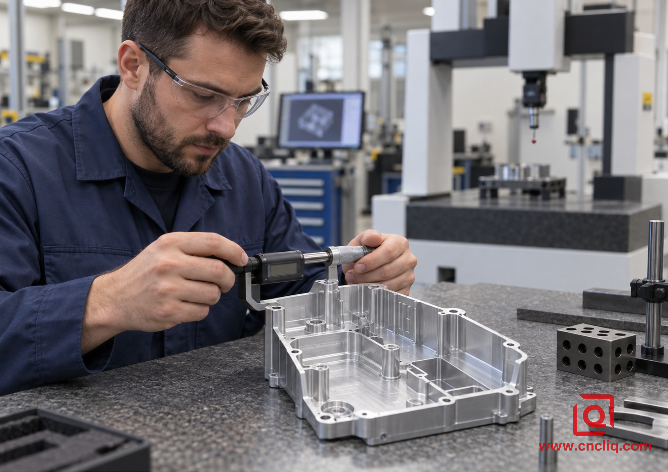
Machinist inspecting a freshly milled aluminum housing
Troubleshooting From the Cut, Not From Guesswork
|
Symptom |
Likely causes |
First action |
|
Aluminum welded to the edge |
Rubbing, poor lubrication, recut chips, unsuitable edge geometry |
Clear chips, inspect the tool, verify chip load, restore lubrication |
|
Squeal or chatter |
Excess stickout, weak fixture, high engagement, unstable speed zone |
Shorten the setup, reduce engagement, check holder and fixture |
|
Powdery chips |
Feed too low for RPM, corner slowdown, dull edge |
Verify actual feed, increase chip load carefully, replace a worn tool |
|
Heavy burr at exit |
Dull tool, poor path direction, unsupported edge |
Use a sharp tool, revise exit, add support or a controlled edge break |
|
Good roughing but poor finish |
Deflection, inconsistent allowance, built-up edge, thermal drift |
Use a uniform finish pass and inspect tool condition and part temperature |
|
Broken tool in a pocket |
Packed chips, sudden engagement, runout, excess reach |
Improve evacuation, smooth the path, inspect runout, shorten the tool |
|
Size changes across a batch |
Tool wear, temperature, datum movement, clamping variation |
Trend measurements, verify workholding, compensate only after cause review |
Change one main variable at a time. Record the accepted tool, holder, stickout, material condition, RPM, feed, ap, ae, coolant method, spindle load, inspection result, and tool life. That setup sheet becomes more valuable than another generic online chart.
Anonymous Customer Case: 6061 Hydraulic Manifold Block
An anonymized industrial customer needed a compact 6061-T6 manifold with intersecting ports, O-ring counterbores, mounting faces, and a cosmetic anodized exterior. The initial concern was not maximum metal removal. It was holding the sealing geometry and port relationships consistently while preventing chips from remaining in deep cross-holes.
The engineering review separated the process into stable stages. The team established broad datum faces first, used a 3-flute aluminum end mill for open roughing, switched to a 2-flute tool where narrow channels restricted chip flow, and reserved stock for sealing-face finishing. Deep regions received directed flushing and an intermediate cleaning check. Critical bores and face relationships were inspected before the cosmetic finish, while threaded and sealing features were protected in the finishing plan.
During the first controlled trial, the process was not released from calculated RPM alone. The team checked actual spindle load, corner behavior, chip form, tool runout, and feature temperature. Feed was adjusted to preserve chip thickness at the available spindle speed, while local engagement controls reduced load at internal transitions. The final setup sheet captured the approved tool assemblies and inspection sequence for repeat batches.
This is the same manufacturing logic used for a custom CNC-machined and anodized hydraulic manifold: parameter selection, workholding, cleaning, dimensional verification, and surface treatment must support one another. If your RFQ includes sealed passages, thin walls, cosmetic faces, or critical position tolerances, send the drawing and annual quantity. Those details change the machining plan and the quotation.
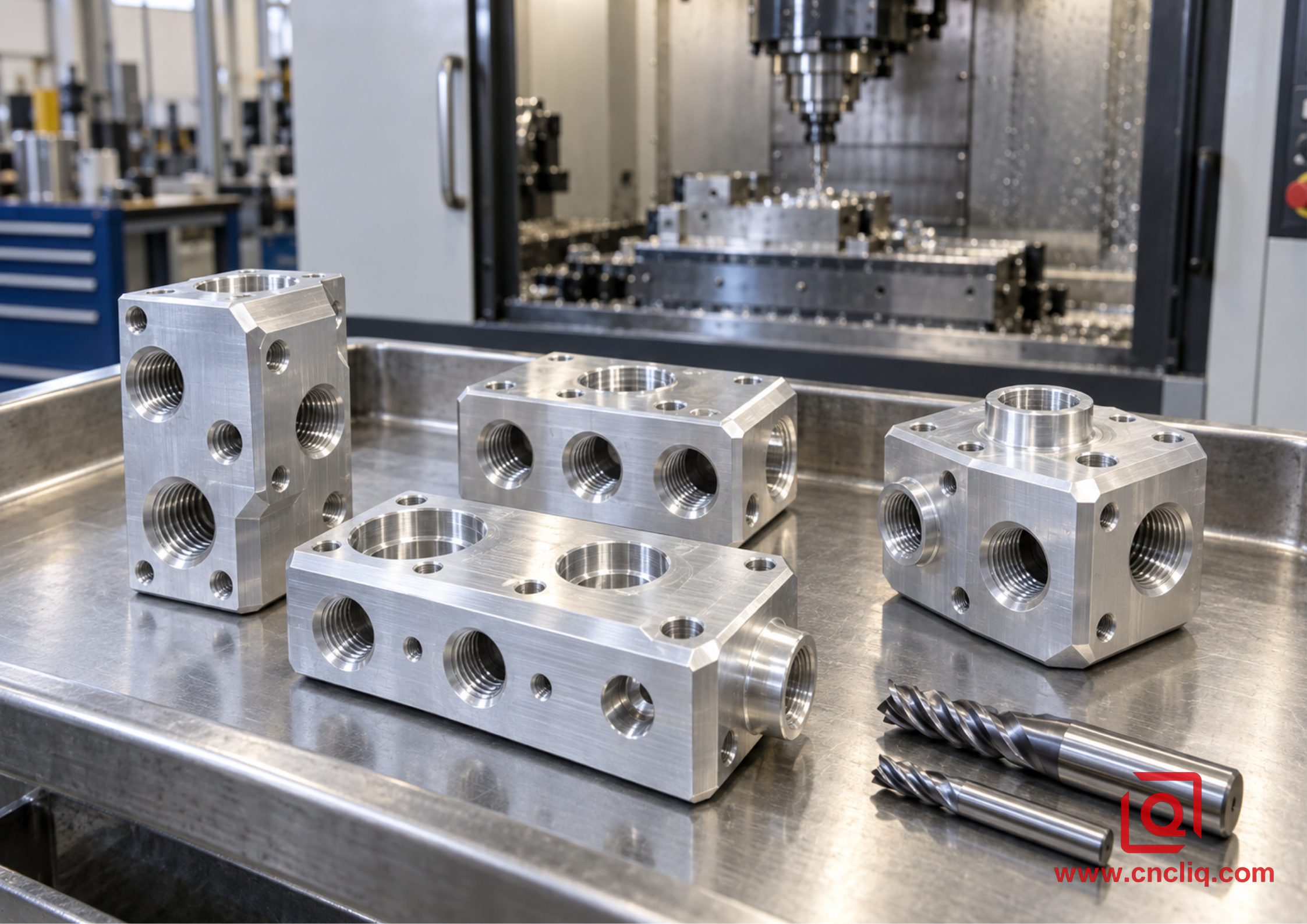
Completed 6061 aluminum manifold blocks and end mills
A Shop-Floor Validation Checklist
1. Confirm alloy, temper, product form, stock condition, and governing drawing revision.
2. Select the exact tool for aluminum and obtain its manufacturer's speed, chip-load, and engagement guidance.
3. Verify holder condition, runout, tool stickout, flute length, and feature access.
4. Calculate RPM from cutting speed, cap it to the machine limit, then recalculate feed from chip load.
5. Review ap, ae, entries, corners, slots, thin walls, and regions where engagement changes.
6. Confirm workholding support, datum repeatability, chip escape, and coolant or air direction.
7. Run a controlled first cut and watch actual feed behavior, spindle load, sound, chips, burrs, and tool edge.
8. Inspect critical dimensions and surface condition with suitable calibrated equipment.
9. Change one variable at a time, document the accepted window, and require approval before production release.
At Liqin, dimensional verification can include CMM, optical projection, height measurement, surface profiling, and roughness measurement according to the part and control plan. See our quality assurance and inspection capabilities for the equipment and quality-system context. A parameter sheet is useful only when the measurement plan proves that the resulting part meets the approved drawing.
What to Include in a 6061 CNC machining RFQ
For a faster and more useful quotation, provide 3D CAD plus a controlled 2D drawing. Identify 6061 temper and stock form, critical dimensions, GD&T datums, surface roughness, edge-break requirements, threads, sealing faces, cosmetic zones, anodizing or other finishing, inspection documentation, annual volume, batch size, packaging, and delivery destination. If a dimension is critical to assembly, mark it instead of relying on a general title-block tolerance.
This information lets the supplier choose a realistic tool path, fixture strategy, inspection sequence, and process window. It also helps separate prototype pricing from repeat-production economics. For parts that require multiple orientations, our overview of 3-axis versus 5-axis precision machining explains why fewer setups can improve access and datum control.
Need a review of a 6061 housing, bracket, manifold, fixture, or other custom component? Upload the drawing through our contact page. Tell us the target quantity, critical features, and required finish so the engineering team can respond with a process-aware quotation instead of a generic price.
FAQ
What RPM should I use for a 1/4-inch end mill in 6061 aluminum?
RPM depends on the exact cutter and target surface speed. At 800 SFM, the calculation is (800 × 3.82) ÷ 0.25 = 12,224 RPM. That is a reasonable calculation example for carbide, but the tool manufacturer's recommendation, machine limit, radial engagement, stickout, coolant, and workholding should decide the trial value. After choosing RPM, calculate feed from the recommended chip load instead of guessing IPM separately.
Is a 2-flute or 3-flute end mill better for 6061?
A 2-flute tool offers more chip space and is often safer for full slots, deep pockets, and limited evacuation. A 3-flute aluminum-specific end mill is often more productive for profiling and adaptive roughing on a rigid machine because it adds an effective cutting edge while retaining useful flute volume. The better choice depends on engagement, reach, spindle capability, and chip clearance—not flute count alone.
Should I use coolant when milling 6061 aluminum?
Use a chip-control method appropriate to the operation. Directed air can work for open cuts, mist adds lubrication, and flood coolant is common when it reaches the cutting zone and carries chips away. Deep pockets and slots need particular attention because coolant volume outside the pocket does not guarantee evacuation at the edge. Always comply with machine, fluid, ventilation, and workplace safety requirements.
Why does aluminum weld to my end mill?
Built-up edge usually develops when heat, pressure, and poor chip removal allow aluminum to adhere to the cutter. Common contributors include too little feed for the selected RPM, a dull or unsuitable edge, chip recutting, poor lubrication, excessive engagement, and long stickout. Stop the cut, clean or replace the tool, correct evacuation, verify actual chip load, and restart with one controlled change rather than simply reducing every parameter.
What information does a CNC supplier need to quote 6061 parts accurately?
Send 3D CAD, a revision-controlled 2D drawing, alloy and temper, critical tolerances and GD&T, surface finish, threads, sealing and cosmetic requirements, post-treatment, quantity, inspection documentation, and delivery needs. Note assembly-critical features and mating parts. A complete RFQ helps the supplier plan workholding, tool access, inspection, finishing allowance, and repeat-production controls, which reduces clarification time and quotation risk.
Summary
Reliable 6061 aluminum milling comes from balancing cutting speed, chip load, flute count, engagement, rigidity, and chip evacuation. Calculate RPM from surface speed, calculate feed from chip load, then correct both for the real machine and toolpath. Use sharp aluminum-specific tooling, keep the setup short and rigid, validate with chips, load, sound, and inspection, and document the approved window. For a process-aware quotation, send Liqin your CAD files, drawing, quantity, material condition, critical tolerances, and finish requirements.
Contact Information
Company: Ningbo Liqin Industry Co., Ltd.
Daily customer maintenance & after-sales support:service@shturl. zhuwanying@cncliq.com
New inquiry, quotation & order discussion:business@shturl. zhouli@chinaliqin.com
Hotline: +86 18757148656
Disclaimer
All technical articles, material specifications, machining recommendations, and surface treatment details published on this blog are for informational and reference purposes only. Please note that general blog insights do not replace signed technical agreements. Because custom parts vary by material heat numbers, machine calibrations, and specific tolerances, binding quality specs are governed solely by your approved CAD drawings, signed contracts, and formal quality plans.
All customer case studies featured on this blog have been thoroughly anonymized and sanitized. The performance metrics, manufacturing workflows, and imagery displayed serve solely to demonstrate our custom machining capabilities and do not represent a single universal standard for all orders.
Liqin Manufacturing Team
Built on 18 years of precision engineering experience, Ningbo Liqin Industry manufactures high-tolerance metal components for demanding global markets. We operate out of a 6,500 m² production hub equipped with over 150 machines, running 4-axis and 5-axis CNC machining, mill-turn machining, cold extrusion, and pressure die casting under one roof. This setup allows us to manage projects seamlessly, taking parts from initial CAD concepts directly to finalized shipments.
We handle quality control with zero compromise. We treat tight tolerances with the engineering discipline they require. Backed by ISO 9001, ISO 13485, and IATF 16949 certifications, our QA engineers run strict IPQC, FQC, and OQC checks on every single production batch. From CMM dimensional mapping and optical profiling to hardness and salt-spray testing, we validate your critical specs upfront—so you receive drop-in ready components with zero assembly headaches or costly line stoppages. On top of manufacturing, you can rely on us for two-hour response times on new RFQs, direct support for prototype sampling, and smooth export shipping across Europe, North America, Asia, and Oceania.
Welcome your inquiries and samples. Visit our website or contact us directly for a competitive quote!
