 English




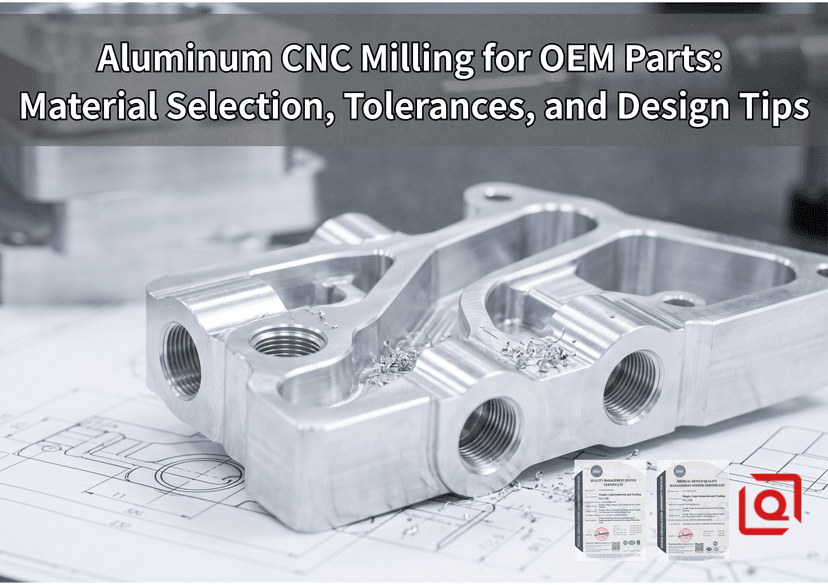
Designing aluminum components for high-volume CNC milling is an ongoing compromise between theoretical engineering intent and physical cutting dynamics. CAD models don't live in a vacuum; every cut contends with cutter load, thermal buildup, and residual internal stress. The moment stock lands on a 3-axis or 5-axis vertical machining center (VMC), tight callouts on your print quickly dictate tool push-off, surface ripple, actual machine run-time, and bin-bound fallout.
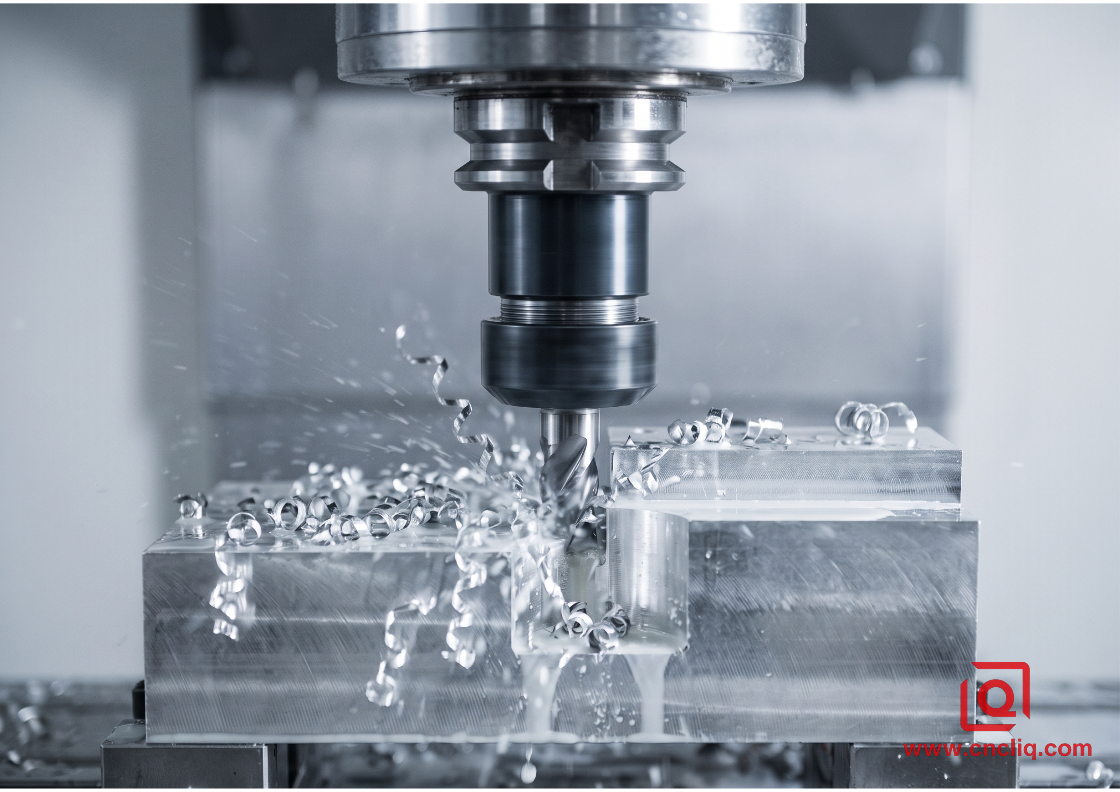
Running consistent, budget-friendly OEM batches comes down to locking down raw stock specs, practical geometric dimensioning and tolerancing (GD&T), and clean manufacturing habits well before posting out the first G-code toolpath.
1. Material Selection: Matching Alloys to Functional Loads
Picking raw bar stock goes way beyond pulling yield figures off a reference chart. Real run-behavior hinges on machinability ratings, chip break-up, and finishing routes like Type II sulfuric or Type III hardcoat anodizing.
- 6061-T6: The standard baseline alloy. Magnesium and silicon additions provide solid rust protection, weld-friendliness, and predictable cutter response. Pushed hard on roughing passes with an uncoated carbide end mill at high surface footage (SFM), 6061 throws tight, curled chips that never pack the flutes. A go-to pick for housings, base plates, and mounting hardware.
- 7075-T6: Heavy-hitting zinc-based grade. Yield strength climbs past 503 MPa—beating mild steel at roughly 1/3 the weight. It machines crisp dry or under light mist, producing sharp edges and slick finishes without smearing. The catch: weaker environmental protection and poor tolerance for brake bending or arc welding. Non-negotiable for flight brackets, high-load arm linkages, and rigid tooling blocks.
- 2024-T351: Copper-loaded formulation built for high cyclical fatigue resistance and fracture durability. Chips break off into tiny needles, so screw conveyors haul them away without snagging on long setups. That copper trade-off invites intergranular attack, making a chem film pass (MIL-DTL-5541 Class 1A) or hard coat non-negotiable.
- 5052-H32: Soft yield threshold, effortless bendability, and top-tier saltwater survival. The snag is extreme gumminess under the cutter. Material loves welding onto tool margins (BUE), so keep flute pockets polished, hook up aggressive rake angles, and run the flood lines wide open.
| Alloy & Temper | Tensile Strength (MPa) | Yield Strength (MPa) | Hardness (HB) | Machinability Index (Base: 2011=100) | Primary Target Applications |
| 6061-T6 | 310 | 276 | 95 | 80 | Brackets, automation frames, enclosures |
| 7075-T651 | 572 | 503 | 150 | 70 | Aerospace mounts, structural load arms |
| 2024-T351 | 469 | 324 | 120 | 75 | Fatigue-critical shafts, hydraulic blocks |
| 5052-H32 | 228 | 193 | 60 | 55 | Marine housings, fluid containment bodies |
2. Tolerances: Balancing Precision Against Machining Physics
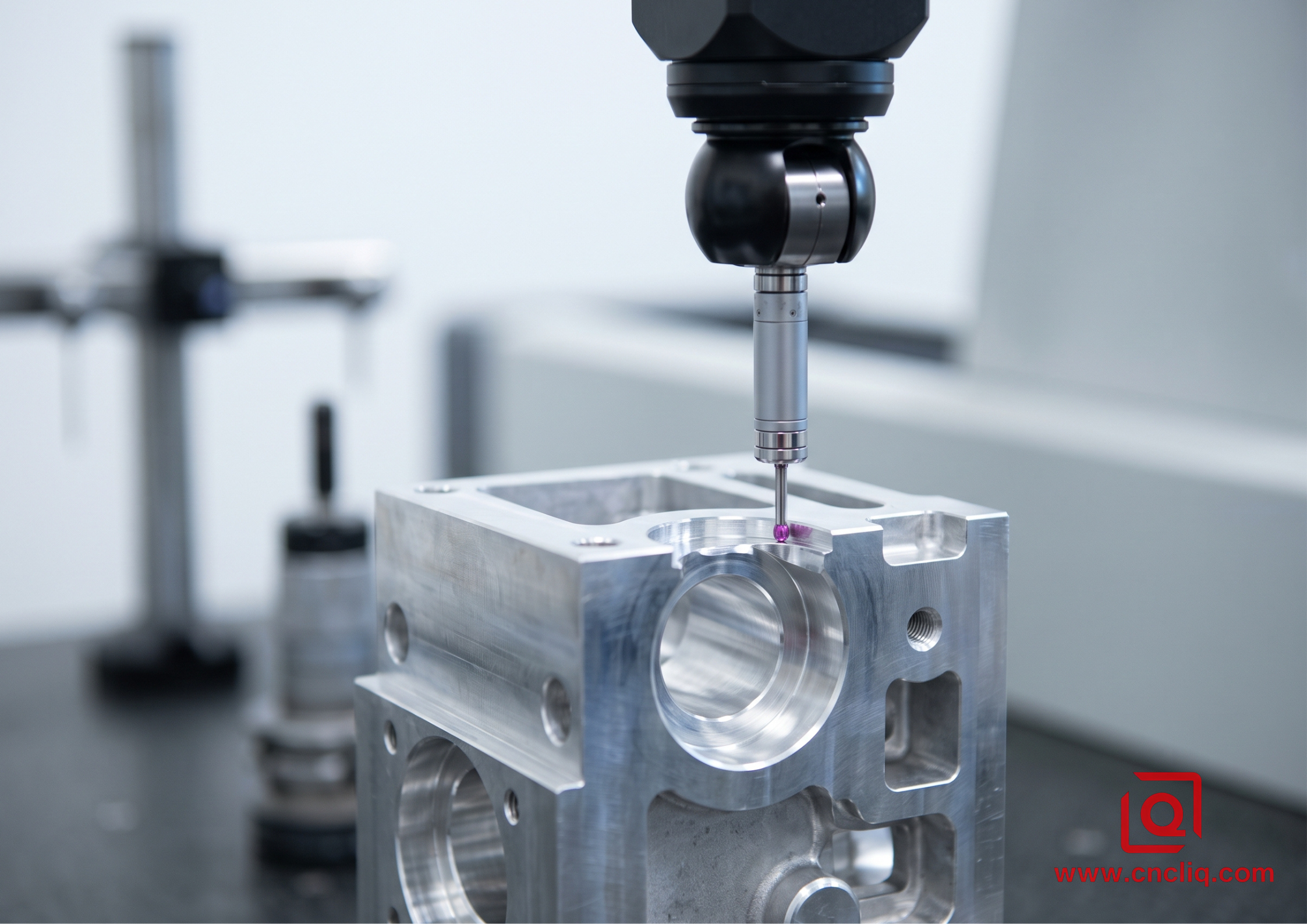
Defaulting to ISO 2768-m (medium) keeps unit economics predictable for common structural components. The trouble begins when designers drop blanket title-block tolerances of ±0.01 mm across non-critical mounting profiles.
Standard Milling Tolerance:      ±0.05 mm to ±0.1 mm  (ISO 2768-m)
Precision Bore Tolerance:        ±0.012 mm to ±0.025 mm (ISO 286-2 JS7/H7)
High-Precision Jig Boring:       ±0.005 mm (Requires controlled shop temp)
Aluminum hates heat traps, expanding at a wild 23 to 24 × 10⁻⁶ / K. Push a 200 mm part through a brutal deck-mill cut and gain merely 5°C; you just packed 0.023 mm of fake growth onto that stock. Drop a stylus into a fresh, cooking pocket, and QA's coordinate measuring machine (CMM) instantly red-tags the piece. Let the metal shed that heat down to an equalized 20°C ambient baseline, and those runaway digits slide cleanly back into print tolerance.
Never try to chase tight bearing bores with an off-the-shelf end mill. Hog it out on a rough pass, leave 0.15 mm a side, let the piece cool down and settle, then clean it up using a solid-carbide reamer or an adjustable micro-boring head dialed to a lighter feed.
3. Design for Manufacturability (DFM) Rules for Milling
Radii, Pockets, and Cavities
Every internal vertical corner needs a radius. End mills are round tools. When pocketing, a sharp 90° corner requires secondary Wire EDM or broaching, inflating unit costs exponentially.
-
Corner Radii Oversizing: If an internal corner requires an R3 mm fillet, don't model an exact R3.0 mm. Use R3.5 mm or R4 mm. An exact 3 mm radius forces a 6 mm cutter into a 90° vector stop, causing tool engagement to spike from 25% to 75% instantly. The cutter chatters, leaves resonant gouges on the wall, and deflects. An oversized radius allows the toolpath to dynamically roll through the corner without decelerating.
-
Depth-to-Width Ratio: Cap pocket depth at 4× tool diameter. Milling deeper than 5× induces harmonic resonance along the tool shank, demanding specialized extended-reach necked cutters, conservative depths of cut (DOC), and slower feed rates.
Wall Thickness and Rib Support
Thin walls behave like tuning forks under tool pressure. High-speed spindle rotation sends vibration waves directly through unsupported uprights, destroying dimensional accuracy and surface finish.
-
Unsupported Walls: Keep a minimum wall thickness of 1.2 mm to 1.5 mm for depths up to 25 mm.
-
Tall Partitions: For walls extending beyond 40 mm high, step the thickness up to at least 2.5 mm, or taper the cross-section by 1° to 2° down to a reinforced root fillet.
-
Clamping Distortion: Avoid positioning thin walls under primary vice contact zones. VMC hydraulic vises can crush or flex a 1.0 mm rib during fixture clamping; the part cuts straight, but upon jaw release, springback bends the feature out of perpendicularity.
Thread Tapping and Thread Milling
-
Hole Depth: Drill tap drill holes deeper than the specified thread length by at least 2× to 3× pitch. Blind holes with zero clearance bottom out the tap, shattering high-speed steel (HSS) tools and scrapping parts.
-
Thread Engagement: Cap active thread engagement length between 1.5× and 2× nominal bolt diameter. Threading an M6 bolt 20 mm deep into 6061-T6 yields zero mechanical retention gain while escalating tap binding hazards.
4. OEM Field Case: Multi-Port Pneumatic Valve Manifold
Background and Requirements
An industrial robotics client approached us to produce an integrated aluminum valve block housing high-speed pneumatic solenoids. The component featured six deep-pocket valve seats, internal intersecting cross-flow fluid channels, and twenty-four threaded ports.
-
Material: Aluminum 6061-T651 billet.
-
Critical Functional Dimensions: Valve spool bores required Ø16.000 mm (+0.015 / -0.000 mm, ISO H7 fit).
-
Surface Roughness: Ra 0.4 µm on the sealing land faces.
-
Geometric Limits: Face planarity within 0.02 mm across the entire 220 mm base to prevent leakage under 0.8 MPa operational line pressure.
Bottlenecks and Shop Observations
The original client CAD file came in with R1.0 mm internal pocket corners at a depth of 32 mm, alongside 0.8 mm thick internal partition walls separating adjacent pressure chambers.
During initial prototype toolpath runs on our DMG MORI 5-axis vertical machining center:
-
The 2 mm micro-end mill running at 14,000 RPM drifted under lateral cutting loads, causing wall deflection and severe chatter bands.
-
Residual stress within the drawn 6061-T6 bar stock released after face-milling the main pockets, bowing the component 0.05 mm across the mounting plane—far outside the 0.02 mm target.
Process Adjustments and Resolution
-
Stress Relieving Step: Switched the raw stock specification to 6061-T651 (stress-relieved by stretching). We ran an aggressive bulk hogging pass, leaving 1.0 mm stock all around, then un-clamped the fixture to allow internal material stresses to balance out before reclamping with light hydraulic pressure (1.2 MPa) for the final skim passes.
-
Radius and Wall Revision: We negotiated with the client's engineering lead to adjust corner fillets from R1.0 mm to R2.5 mm and expanded internal partition walls from 0.8 mm to 1.6 mm. This let our programmers deploy a rigid 4 mm corner-rounding end mill, boosting chip removal rates by 280%.
-
Precision Boring: Instead of circular interpolation milling for the valve spool bores, we rough-bored to Ø15.7 mm, followed by a dedicated fine-boring head running a single-point cBN insert at 3,200 RPM and a 0.04 mm/rev feed rate.
The resulting run achieved the target bore size at Ø16.008 mm, surface finish hit Ra 0.32 µm, and total flatness held steady at 0.012 mm across all production units.
5. Surface Finishing: Calculating Anodize Allowances
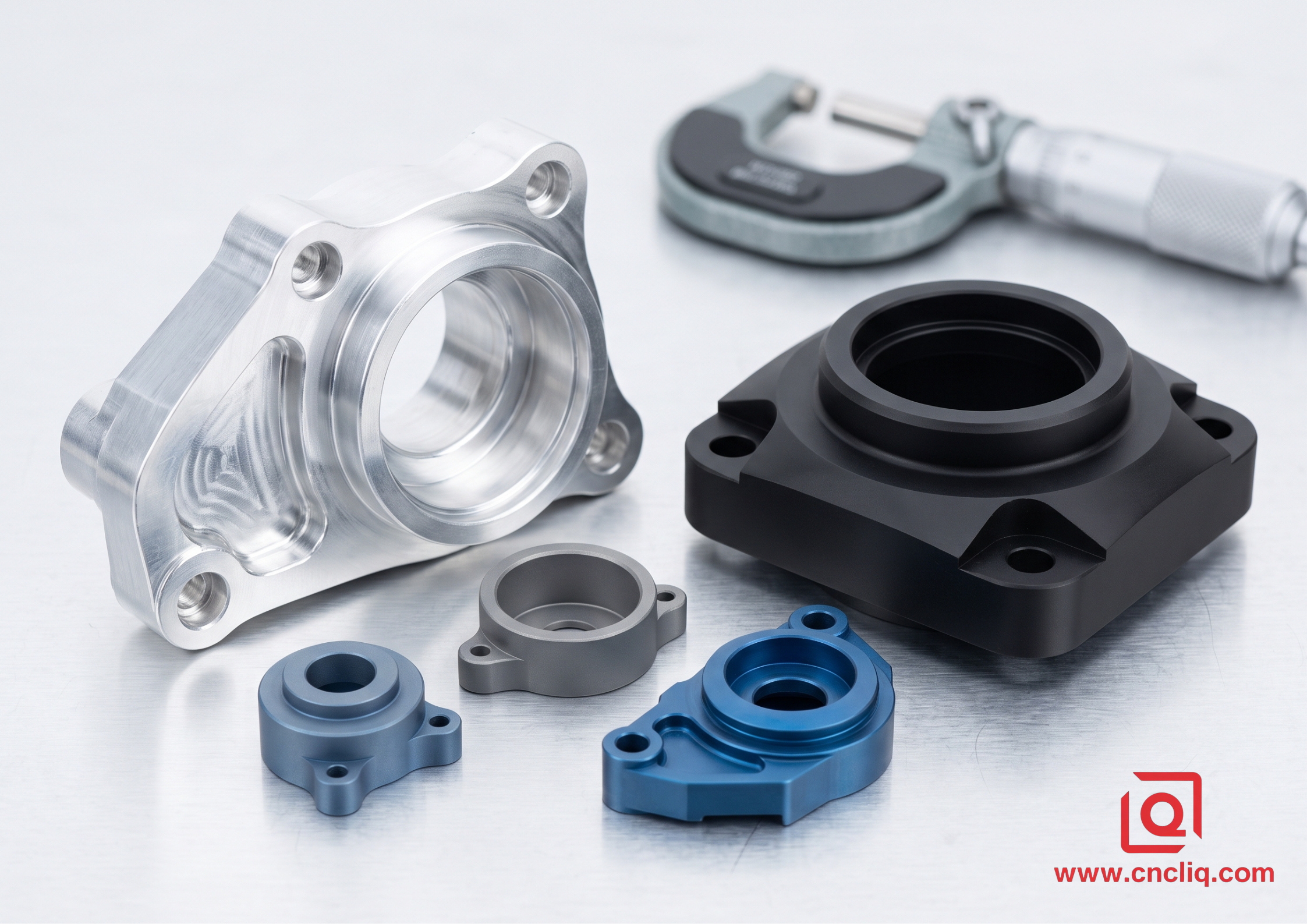
Never hand off a print for anodizing without accounting for dimensional dimensional offsets.
-
Type II Anodizing (Sulfuric Acid Bath, ISO 7599): Builds roughly 10 µm to 25 µm total coating thickness. Around 50% of the film penetrates the raw aluminum matrix, while 50% builds up outward. Diameters grow by roughly half the total thickness per side.
-
Type III Hardcoat (MIL-A-8625 Type III): Yields 35 µm to 50 µm thickness for maximum wear resistance. A 50 µm hardcoat builds outward by 25 µm per surface, shrinking a precision bore diameter by 0.05 mm.
Rule for Prints: Always specify whether callouts apply before or after surface treatment (e.g., "Dimensions apply after anodizing"). When tight bearing diameters or ground guide pins are in play, specify internal plug masking or apply an explicit machining pre-plate tolerance offset.
FAQs
Q1: How do you stop large, unbalanced pocket millings from curling up like a potato chip?
A: Tackling part potato-chipping boils down to three straightforward rules. Start with pre-stretched, stress-relieved plate stock (like 6061-T651 per AMS 4027 or 7075-T651). Never combine roughing with final passes: hog out bulk meat symmetrically off both sides, parking a 0.8 mm to 1.2 mm clean-up skin. Back off the hydraulic vise jaws entirely to let the core breathe, then snug it back down under featherlight, even clamp load (or switch over to a vacuum plate) for final high-speed cleanup skim passes.
Q2: Do 2D print dimensions mean raw cut metal or fully plated parts?
A: General machining convention dictates that every print callout governs the finished article, post-coating, unless a note explicitly states otherwise. A basic Type II anodize deposits roughly 5–12 µm a side, while Type III hardcoat packs on 25–35 µm per face (collapsing hole diameters by as much as 0.05–0.07 mm). Your print has to flag whether critical pin bores need pre-coat machining stock backed out, or simply require physical silicone plugs during tank dips.
Q3: When is paying the premium for 7075-T6 over 6061-T6 actually justified on OEM runs?
A: Step up to 7075-T6 only when pure shear thresholds, heavy yield demands (>500 MPa), and cyclical fatigue limits blow past raw billet expenses—think flight lugs, racecar upright knuckles, or thick-walled valve manifolds. When the job leans toward lean piece prices, real-world weather survival, deep thin-rib machining, or bright-dip cosmetic color lines, 6061-T6 holds down the everyday baseline.
Q4: What CAD modeling blunder blows out CNC run times fastest on aluminum housings?
A: Squaring out interior standing pockets or locking fillets to exact cutter diameters (such as dropping an exact R3.0 mm corner into a 30 mm pocket depth). That corner traps programmers into skinny, long-reach mills running overhangs past 5:1, which starts violent chatter unless you pull feeds back by 70%. Bumping that corner out by just 15% to 20% (up to R3.5 mm or R4.0 mm) frees up trochoidal toolpaths to whip through the turns without slamming on the brakes.
Q5: How do you dodge torn threads and snapped taps down in small aluminum blind holes (like M2 to M4)?
A: Soft grades like 6061-T6 tend to cough up long, bird-nested ribbons under standard cutting taps, packing tight pockets until the tool snaps clean off. We swap those out for cold-forming roll taps across the M2 to M6 range. Form taps cold-flow the parent alloy rather than shearing off swarf, sidestepping packed-chip jamming while forging thread flanks up to 20% stronger. Step up to tough 7075-T6 or tight-tolerance dowel hole groups, and we move straight to single-point helical thread milling with high-pressure through-spindle air or coolant blast. That blast clears every loose chip out of deep holes, ensuring no operator spends his shift EDM-burning a busted tap out of a finished casting.
Summary
Dialing in OEM aluminum components on a mill means locking down the alloy, sane tolerance stacks, and practical machining guidelines well before posting any code. Pairing the right grade—say, stress-relieved 6061-T651 to keep deep cavities flat, or 7075-T6 for heavy-load lugs—straight to part mechanics heads off bowed stock, cutter squeal, and pulled threads. Calling out sensible limits via ISO 2768-m, factoring in thermal growth, and leaving generous internal fillets alongside rigid wall sections cuts run-times down while slashing part fallout. Nailing the small stuff early, from plating buildups to roll-forming blind threads, keeps your batch moving cleanly from CAD solid to stable, budget-friendly finished parts.
Contact Information
Disclaimer
All technical articles, material specifications, machining recommendations, and surface treatment details published on this blog are for informational and reference purposes only. Please note that general blog insights do not replace signed technical agreements. Because custom parts vary by material heat numbers, machine calibrations, and specific tolerances, binding quality specs are governed solely by your approved CAD drawings, signed contracts, and formal quality plans.
All customer case studies featured on this blog have been thoroughly anonymized and sanitized. The performance metrics, manufacturing workflows, and imagery displayed serve solely to demonstrate our custom machining capabilities and do not represent a single universal standard for all orders.
Liqin Manufacturing Team
Built on 18 years of precision engineering experience, Ningbo Liqin Industry manufactures high-tolerance metal components for demanding global markets. We operate out of a 6,500 m² production hub equipped with over 150 machines, running 4-axis and 5-axis CNC machining, mill-turn machining, cold extrusion, and pressure die casting under one roof. This setup allows us to manage projects seamlessly, taking parts from initial CAD concepts directly to finalized shipments.
We handle quality control with zero compromise. We treat tight tolerances with the engineering discipline they require. Backed by ISO 9001, ISO 13485, and IATF 16949 certifications, our QA engineers run strict IPQC, FQC, and OQC checks on every single production batch. From CMM dimensional mapping and optical profiling to hardness and salt-spray testing, we validate your critical specs upfront—so you receive drop-in ready components with zero assembly headaches or costly line stoppages. On top of manufacturing, you can rely on us for two-hour response times on new RFQs, direct support for prototype sampling, and smooth export shipping across Europe, North America, Asia, and Oceania.
Welcome your inquiries and samples. Visit our website or contact us directly for a competitive quote!
