 English




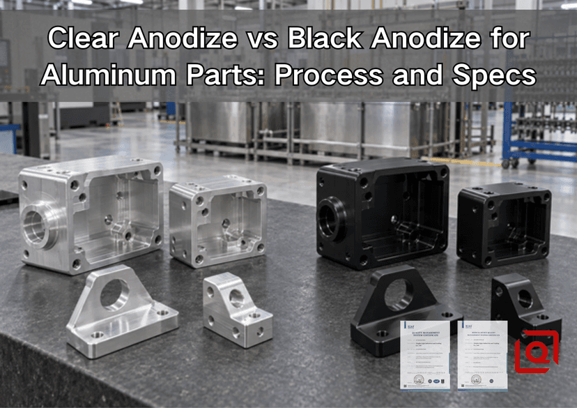
Are you still deciding between clear anodize and black anodize for a precision aluminum part—and worried that a simple color choice could become a tolerance, color-match, or assembly problem? This guide explains what changes in the tank, what belongs on the drawing, and what a buyer should approve before production. It comes from a shop-floor point of view, where a note such as “anodize black” is not a complete specification. It is only the start of the conversation.
For most CNC aluminum components, the quick answer is simple. Clear and black Type II anodize use the same basic sulfuric-acid oxide-forming stage. Clear anodize is sealed without dye and normally keeps a silver-to-gray metallic appearance. Black anodize adds a dye bath before sealing, producing a dark, lower-reflectance surface. Their base protection can be comparable when alloy, oxide thickness, sealing, and acceptance requirements are equal. Choose by function, appearance, environment, dimensional risk, and inspection—not by color alone.
Practical rule: choose clear for a natural metal appearance and no dye-related color target. Choose black when glare control, visual identity, optical stray-light control, or a uniform dark exterior matters. Choose Type III hardcoat—not simply “black”—when abrasion and wear are the main engineering drivers.
What Clear and Black Anodizing Actually Mean
Anodizing does not lay a skin of paint over the metal. Instead, the part serves as the anode while current drives a controlled reaction that turns its surface into porous aluminum oxide. Some of that oxide occupies metal that was already there; the rest rises above the old surface. That detail matters at every close fit.
Under MIL-PRF-8625 terminology, Class 1 is non-dyed and Class 2 is dyed. In this context, “clear” simply says that no dye was used. It says nothing about a guaranteed silver shade. Likewise, “black” names the dye. A buyer still has to call out the Type, film thickness, gloss, seal, and performance checks. NASA/JSC’s PRC-5006 Rev. D process specification likewise identifies Class 1 as non-dyed and Class 2 as dyed, requires the Class 2 color in the drawing note, and emphasizes surface preparation and planned rack-contact locations.
|
Decision point |
Clear anodize |
Black anodize |
|
Typical Type II callout |
MIL-PRF-8625, Type II, Class 1 |
MIL-PRF-8625, Type II, Class 2, black |
|
Dye step |
No dye; seal after rinsing |
Black dye enters open pores before sealing |
|
Appearance |
Silver, satin gray, or alloy-dependent natural tone |
Black from satin to semi-gloss, controlled by pretreatment and sample |
|
Main buying reason |
Natural look, protection, easy damage visibility |
Low reflectance, product identity, dark cosmetic finish |
|
Typical Type II shop range |
Often 5–25 µm; drawing must state the required value or range |
Often 8–25 µm; dye and sealing must be controlled |
|
Electrical behavior |
Oxide is insulating |
Oxide remains insulating; dye does not restore conductivity |
|
Main risk |
Unexpected gray, yellow, or bronze tone |
Shade mismatch, bronze cast, fading, or poor seal |
Those thickness figures are common commercial ranges, not universal defaults. The current purchase specification and approved drawing control the job. The Aluminum Anodizers Council’s anodic-finish guidance also treats alloy, surface condition, film thickness, and coloring route as parts of a finish designation rather than reducing anodize to a color word.
The Process: One Shared Route, One Important Extra Step
A stable anodized finish begins before the anodizing tank. The final oxide follows the existing texture. It will not level cutter marks, blend a weld, or hide a hand-polished patch.
1. Review: verify alloy, temper, lot, cosmetic faces, threads, close fits, electrical contacts, and drainage.
2. Clean: wash away coolant, fingerprints, polishing paste, and the fine dirt that settles on a part between operations. A faint coolant film that looks harmless at the bench may show up later as a stain or a pale patch in the dye.
3. Create texture: bead blast, brush, polish, or retain the machined finish exactly as the drawing requires.
4. Etch and deoxidize: control the satin effect and remove alloy-rich smut.
5. Rack: provide reliable electrical contact. The contact leaves a small uncoated witness, so its location must be acceptable.
6. Anodize: run the tank to its qualified window for current density, chemistry, temperature, and time; chasing one number while the others drift is a poor bargain.
7. Color: Class 1 parts skip dye. Class 2 black parts enter a controlled dye bath while pores remain open.
8. Seal: close the pores using the approved route to improve stain and corrosion resistance.
9. Inspect: verify thickness, final dimensions, color, seal, masking, contact marks, cleanliness, and required reports.
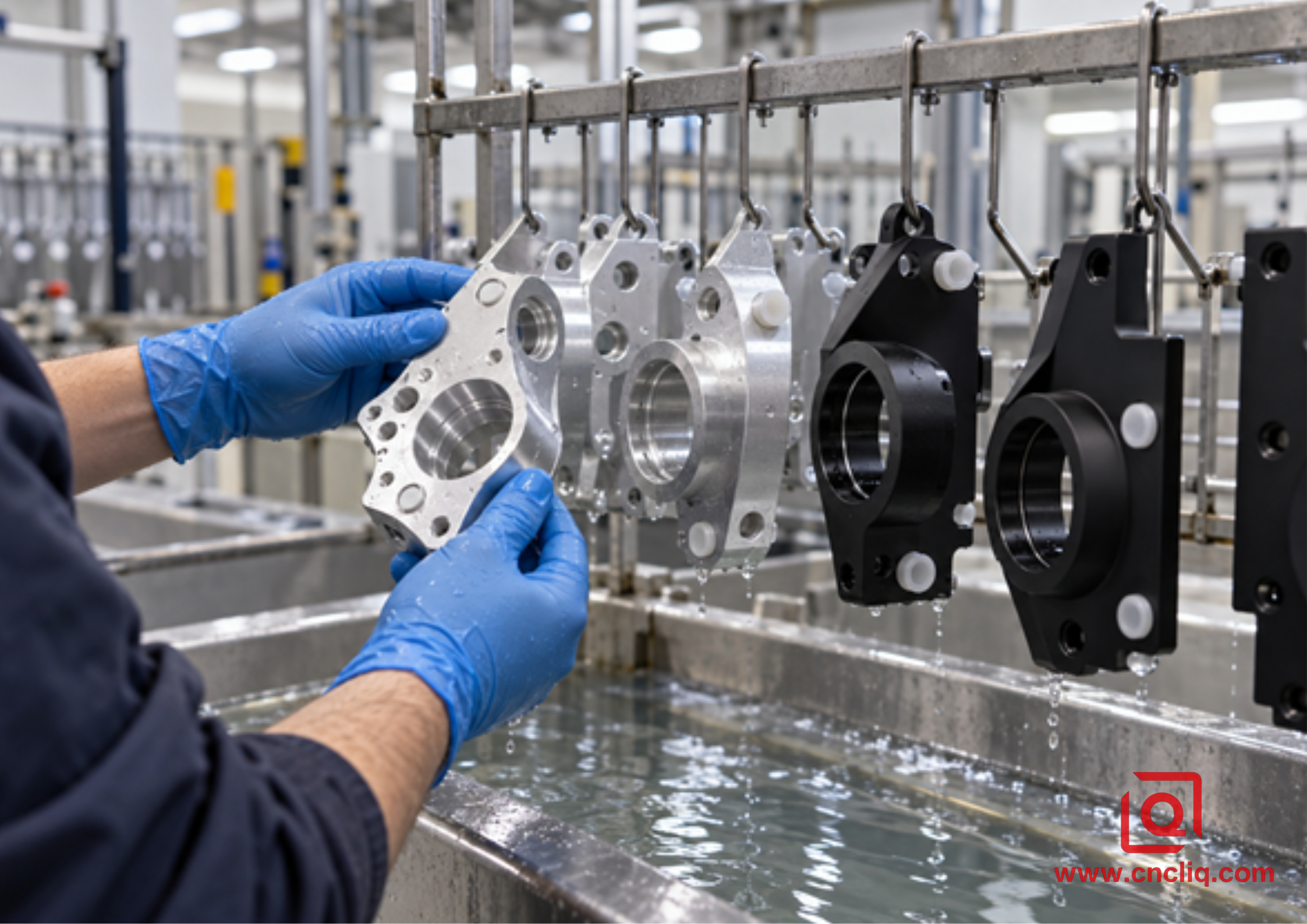
Racking, masking, rinsing, dyeing, and sealing all affect the delivered part; color is only one process variable.
Type II or Type III Comes Before Clear or Black
A frequent RFQ mistake is to compare clear with black before choosing the anodize type. Color and coating duty are separate decisions. Type II sulfuric anodize is widely used for housings, brackets, panels, heat-sink structures, medical equipment parts, and industrial hardware. It provides useful corrosion protection and a broad cosmetic range without the large dimensional effect of a thick hardcoat.
Type III hardcoat uses colder, more tightly controlled conditions to form a thicker, harder oxide for sliding, abrasive, or high-wear surfaces. It may be Class 1 non-dyed or Class 2 dyed. Natural hardcoat can look gray, charcoal, bronze, or olive rather than bright silver. Black hardcoat can also vary with alloy and thickness. If appearance is critical, approve a sample made from the production alloy with the production pretreatment.
For wider finish selection, see Liqin’s surface finishes guide for custom aluminum OEM parts. For tight fits and hardcoat, the Type III anodizing DFM guide adds detail on dimensional growth and masking.
Alloy, Texture, and Color Consistency
Alloy belongs in the finishing specification. When buyers care about a repeatable cosmetic surface, shops usually have an easier time with wrought 5xxx and 6xxx material. That is one reason 6061 turns up so often in housings and brackets: it machines cleanly, carries useful strength, and usually gives the finisher a predictable starting point. High-strength 2xxx and 7xxx grades can anodize successfully, but copper or zinc can shift the natural tone. Die castings tell a different story. With plenty of silicon and local flow variation, their anodized skin may come back gray, cloudy, or mottled.
Do not combine machined, forged, extruded, welded, and cast regions and expect one identical shade without sampling. Grain flow, intermetallic particles, weld filler, and local heat alter the response to etching. For cosmetic production, use one alloy and temper, hold the material lot where practical, run mating parts together, and lock the pretreatment route.
A screen color is weak acceptance evidence. Use a signed physical master plus light and dark boundary samples. State viewing light, angle, and distance. If 2 panels must match in assembly, identify them as a set and process them in the same controlled lot.
Dimensional Growth: The Risk Hidden in a Color Choice
Anodic oxide grows partly into and partly above the original aluminum. A roughly 50/50 split is a useful DFM estimate for conventional sulfuric anodizing, but the actual ratio depends on alloy and process. With 20 µm total oxide, a planning estimate is about 10 µm outward growth on each treated surface. A treated bore can therefore lose about 20 µm in diameter—enough to bind a close dowel fit.
Use the estimate for design review, then contract to the approved process. Precision features generally need one of 4 responses: pre-compensate the machined size; mask bearing seats, threads, seals, or contacts; perform a controlled post-finish operation where exposed aluminum is acceptable; or redesign the interface so the finish is outside the critical fit.
State whether dimensions apply before or after finishing. Avoid “anodize all surfaces” when the part contains a precision bore, insert, grounding pad, O-ring land, or optical seat. Mark masking boundaries and acceptable rack zones on the drawing.
How to Specify Clear or Black Anodize on a Drawing
Clear Type II starting format: ANODIZE PER MIL-PRF-8625, TYPE II, CLASS 1. COATING THICKNESS 10–15 µm. SATIN FINISH ON COSMETIC SURFACES. DIMENSIONS APPLY AFTER FINISH UNLESS NOTED. MASK IDENTIFIED THREADS AND GROUNDING PAD. RACK CONTACT PERMITTED ON INTERNAL FACE C ONLY.
Black Type II starting format: ANODIZE PER MIL-PRF-8625, TYPE II, CLASS 2, BLACK. COATING THICKNESS 12–18 µm. COLOR AND GLOSS TO APPROVED LIMIT SAMPLES. DIMENSIONS APPLY AFTER FINISH. NO VISIBLE RACK MARKS ON SURFACES A OR B.
These are drafting examples, not universal specifications. Before release, define the governing revision, Type and Class, thickness and measurement area, pretreatment, cosmetic faces, physical color limits, mask zones, rack zones, dimensional timing, service environment, inspection method, and required reports.
|
Application |
Likely route |
Critical check |
|
Machine-vision camera housing |
Black Type II; Type III only if wear justifies it |
Mask grounding; define inside glare and outside cosmetic limits |
|
Laboratory instrument frame |
Clear Type II |
Hold alloy, lot, and brushing direction |
|
Hydraulic manifold |
Clear or black by identification need |
Protect sealing lands and ports; verify cleanliness |
|
Consumer electronics enclosure |
Black Type II |
Approve shade, gloss, rack marks, scratches, and assembly match |
|
Sliding actuator element |
Type III |
State thickness, seal, final fit, mate, and lubrication |
Anonymous Customer Case: Matched Optical Sensor Housings
An anonymized European automation customer requested 120 CNC-machined 6061-T6 sensor housings. The exterior needed a matte-black appearance, an internal pad had to remain conductive, and 2 bores located a lens carrier. The original RFQ said only “black anodized,” leaving Type, thickness, bore condition, grounding, and acceptable shade unresolved.
The DFM review converted that phrase into a workable route: one verified material lot; one satin pretreatment; Type II Class 2 black on the exterior; masked grounding pad and selected threads; bore compensation for planned growth; and a hidden internal rack zone. Sample pieces established the acceptable shade and gloss window before the 120-piece run.
The inspection plan combined post-finish bore measurement, eddy-current thickness checks on accessible flats, visual comparison under agreed lighting, thread gauges after de-masking, and continuity verification on the exposed pad. The goal was not an abstract “perfect black.” It was a housing that assembled, grounded, and matched.
The same thinking applies to fluid-control parts. Liqin’s custom CNC-machined anodized hydraulic manifold is the kind of product where port cleanliness, sealing faces, masking, and post-finish inspection outrank the color name.
Does your print still say only “clear anodize” or “black anodize”? Send the CAD model, 2D drawing, annual quantity, alloy, mating details, and cosmetic expectations to Liqin’s engineering team. A pre-quote DFM review can expose coating-build, masking, racking, and color-control risks before they become rejected parts.
Quality Control and Common Failure Signals
Appearance alone cannot release a precision anodized part. A useful control plan links the drawing to material traceability, pre-finish dimensions where compensation is used, final CMM or gauge results, coating thickness, seal quality, mask boundaries, rack marks, color limits, and cleanliness.
For thickness checks on a suitable flat area, inspectors commonly work to ASTM B244 or ISO 2360 and record the actual instrument locations. If salt spray belongs in the quality plan, do not stop at the test name. Write down the exposure time, specimen preparation, and the exact failure limit. “Pass ASTM B117” is incomplete: ASTM B117 defines a test environment, not one universal pass/fail limit for every product.
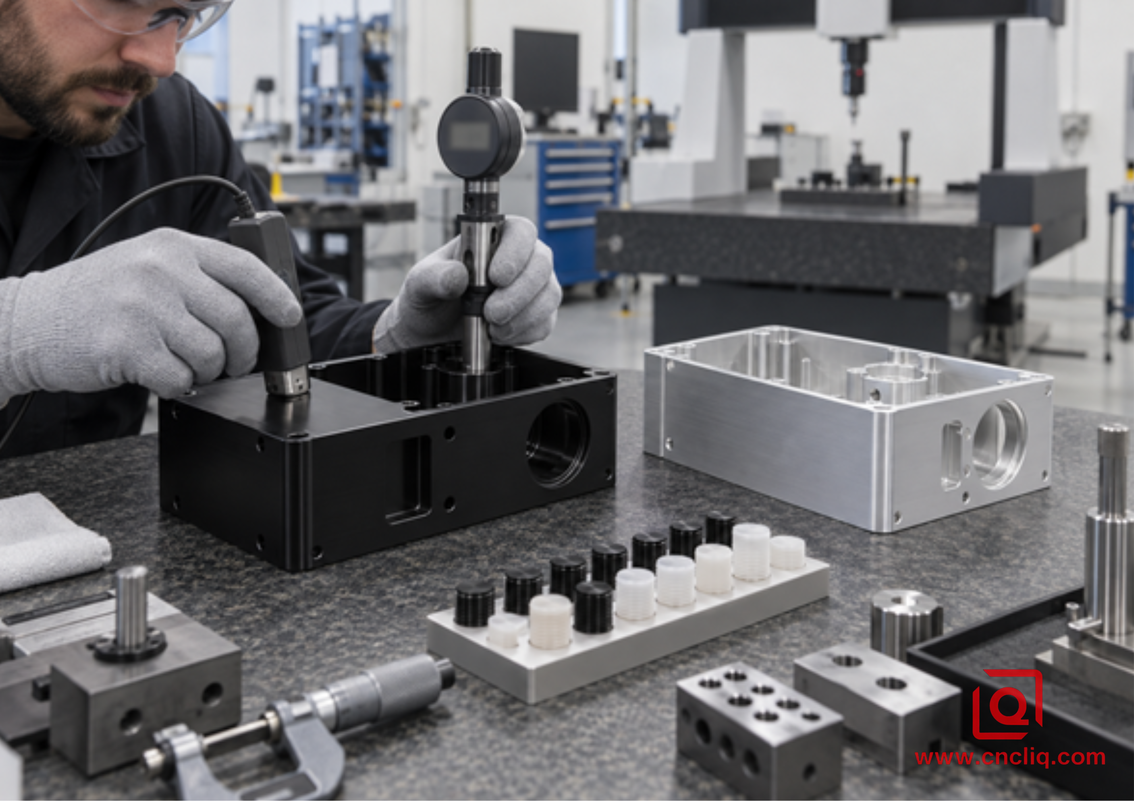
Thickness, finished bores, masking, and appearance limits should be checked together; an attractive finish can still fail assembly.
|
Signal |
Likely contributors |
Response |
|
Clear part looks gray or bronze |
Alloy chemistry, etch, thickness, mixed route |
Confirm alloy and lot; approve samples; lock pretreatment |
|
Black shade varies |
Mixed lots, inconsistent texture, thickness, dye, or load position |
Run matched sets together; maintain bath control; use limit samples |
|
Black turns brown or rubs |
Poor dyeing/sealing or incompatible exposure |
Review seal verification, UV, cleaners, and environment |
|
White spots or stains |
Trapped rinse, poor drainage, contamination |
Add drainage, improve rinsing/drying, protect handling |
|
Tight bore or thread |
Coating build omitted from tolerance stack |
Compensate, mask, redesign, and inspect after finish |
|
Bare mark on cosmetic face |
No approved rack location |
Mark rack zones and review fixture access |
Cost, Lead Time, and the RFQ Package
Black dye is rarely the only cost difference. Lot size, rack difficulty, masking hours, color sorting, inspection, and rejection risk often matter more. A small housing with 18 masked holes can cost more to finish than a larger plain plate. Tight color limits may add samples, one-lot processing, and approval time. Type III adds thickness and dimensional-control work.
For a dependable quotation, provide the model and drawing, alloy and temper, Type and Class, thickness, texture, color sample, cosmetic faces, mask and rack zones, final tolerances, inspection and corrosion criteria, quantity, annual demand, service conditions, mating details, and packaging expectations. For machining-route context before finishing, Liqin’s 3-axis versus 5-axis CNC machining guide explains why datum control and setup count matter.
Buyer’s 9-Point Decision Checklist
- Define the duty: appearance, glare, corrosion, wear, insulation, or identification.
- Select Type II or Type III before choosing color.
- Select Class 1 non-dyed or Class 2 dyed black.
- Lock alloy and temper; control lots for matched cosmetic parts.
- Define texture: machined, etched, blasted, brushed, or polished.
- Circle the dimensions that apply after finishing, then show where the shop may compensate, mask, and attach a rack.
- Approve physical master and boundary samples for critical appearance.
- Turn “looks good” into measurable release checks for thickness, sealing, fit, appearance, cleanliness, and corrosion.
- Finally, send the full RFQ package. A price built on missing finish details is only a guess with a currency symbol.
FAQs
1. Is black anodize more corrosion-resistant than clear anodize?
Not automatically. Put the same alloy through the same Type, thickness, seal, and inspection plan, and the two colors should be judged on the same corrosion basis. Black dye mainly changes appearance. Control corrosion through the complete specification and acceptance plan rather than inferring performance from color.
2. Does clear anodize always remain bright silver?
No. Clear means non-dyed, not colorless. Alloy, temper, grain, etching, thickness, and sealing can shift the tone to satin gray, yellowish, bronze, or olive. Natural Type III hardcoat is often darker. Use an alloy-matched sample when the final tone matters.
3. Can anodizing hide machining marks or scratches?
No. It follows the existing surface and may make variation more visible. Define the pretreatment before anodizing. Black dye should not be expected to hide dents, deep cutter marks, weld variation, local hand blending, or inconsistent bead blasting.
4. Should threaded holes be masked?
It depends on thread size, finish thickness, fit, fastener system, and electrical needs. Fine internal threads and close fits are more sensitive, especially with Type III. Review each critical thread, show mask requirements on the print, and gauge the delivered feature after finishing.
5. How can a buyer control cost and lead time without weakening quality?
Send a complete RFQ early, separate functional from cosmetic faces, allow practical rack points, avoid unnecessarily narrow color limits, and approve samples before volume production. Ask the supplier to identify masking and tolerance risks during DFM. Where confidentiality matters, use the signed NDA and controlled file-transfer route agreed with the supplier.
Summary
Clear and black anodize share the same basic oxide-forming process; black adds dye before sealing, while clear remains non-dyed. Select Type II or Type III first, then Class 1 or Class 2. Lock alloy, texture, thickness, final dimensions, masking, rack zones, physical color limits, and inspection. A complete drawing and RFQ turn a subjective color request into a controlled manufacturing specification that protects fit, appearance, and delivery.
Contact Information
Company: Ningbo Liqin Industry Co., Ltd.
Daily customer maintenance & after-sales support:service@shturl. zhuwanying@cncliq.com
New inquiry, quotation & order discussion:business@shturl. zhouli@chinaliqin.com
Hotline: +86 18757148656
Disclaimer
All technical articles, material specifications, machining recommendations, and surface treatment details published on this blog are for informational and reference purposes only. Please note that general blog insights do not replace signed technical agreements. Because custom parts vary by material heat numbers, machine calibrations, and specific tolerances, binding quality specs are governed solely by your approved CAD drawings, signed contracts, and formal quality plans.
All customer case studies featured on this blog have been thoroughly anonymized and sanitized. The performance metrics, manufacturing workflows, and imagery displayed serve solely to demonstrate our custom machining capabilities and do not represent a single universal standard for all orders.
Liqin Manufacturing Team
Built on 18 years of precision engineering experience, Ningbo Liqin Industry manufactures high-tolerance metal components for demanding global markets. We operate out of a 6,500 m² production hub equipped with over 150 machines, running 4-axis and 5-axis CNC machining, mill-turn machining, cold extrusion, and pressure die casting under one roof. This setup allows us to manage projects seamlessly, taking parts from initial CAD concepts directly to finalized shipments.
We handle quality control with zero compromise. We treat tight tolerances with the engineering discipline they require. Backed by ISO 9001, ISO 13485, and IATF 16949 certifications, our QA engineers run strict IPQC, FQC, and OQC checks on every single production batch. From CMM dimensional mapping and optical profiling to hardness and salt-spray testing, we validate your critical specs upfront—so you receive drop-in ready components with zero assembly headaches or costly line stoppages. On top of manufacturing, you can rely on us for two-hour response times on new RFQs, direct support for prototype sampling, and smooth export shipping across Europe, North America, Asia, and Oceania.
Welcome your inquiries and samples. Visit our website or contact us directly for a competitive quote!
