 English




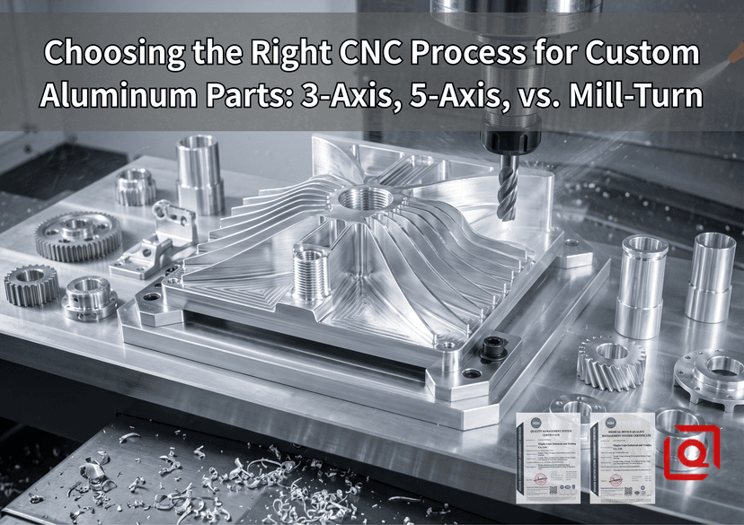
Machining aluminum often carries a misleading reputation on the design floor. Because aluminum cuts cleanly and clears chips quickly under high spindle speeds, many assume that getting a custom component out of stock metal is straightforward. Then the rough-machined stock comes off the table, and real-world shop dynamics reveal themselves. Thin web walls bow outward under internal material stress. Critical bore centerlines drift out of true across a secondary manual flip. The anodizing house calls to report that mismatched tool marks across two setups show through the surface treatment.
Precision aluminum work hinges on locking down datum shifts, tool deflection, clamp rigidity, and cycle pace. Picking between a basic 3-axis mill, a 5-axis trunnion, or a dual-spindle turn-mill setup isn’t about showing off iron; it is about keeping tolerances tight. It is a calculated decision based on part geometry, tolerances, and batch volume.
1. 3-Axis CNC Milling: The Workhorse for Prismatic Components and Open Cavities
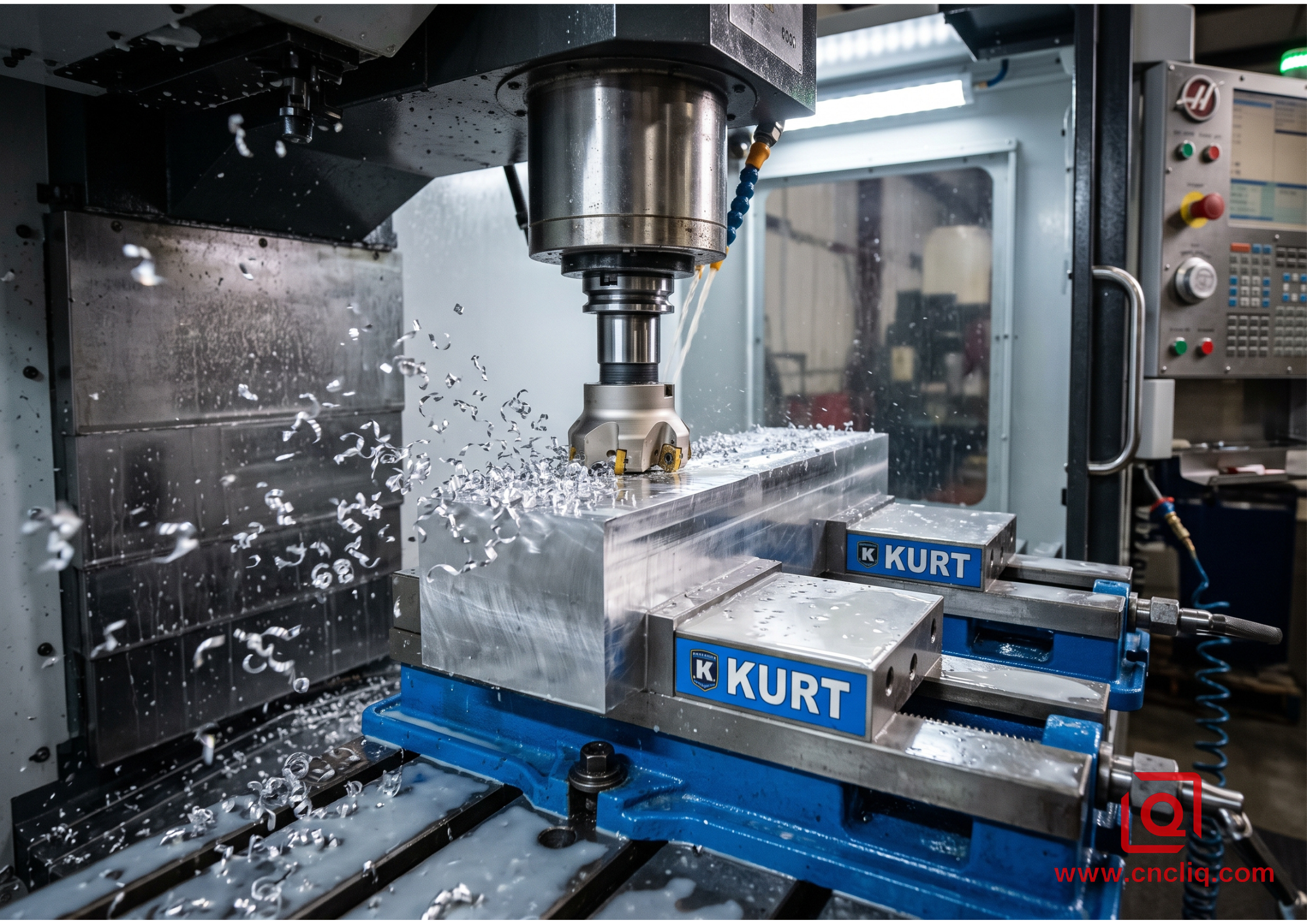
When an aluminum component can be reached entirely from a single top-down orientation without hidden undercuts or angled side ports, the traditional 3-axis vertical machining center remains the most economical solution.
Top-Down 3-Axis Approach:
[ Vertical Spindle Travel: Z-Axis ]
                 |
                 v
        +-----------------+
        | End Mill Cutter |
        +-----------------+
                 |
   [ Table Travel: X & Y Axes ] ----> Rigid vise setup on machine bed
Where 3-Axis Excels
A standard 3-axis machine carries significant physical mass relative to its working envelope.The spindle moves vertically along the Z-axis while the heavy cast-iron worktable carries the workpiece along the X and Y axes. This structural mass absorbs cutting vibrations effectively during heavy pocket hogging.
-
Open, planar profiles: Mounting plates, flat heat sinks, structural flanges, electronic chassis baseplates, and bracketry.
-
Rapid bulk metal removal: Pocketing out large volumes of material from solid aluminum plate using aggressive roughing cutters. The rigidity of a locked table lets operators push cutting tools hard without risking mechanical chatter.
-
Straightforward shop tooling: Workpieces secure into standard Kurt-style vises, vacuum chucks, or custom aluminum soft jaws cut directly on the machine bed during setup.
The True Trade-Off: Fixture Stacking and Part Flips
The natural limitation of a 3-axis mill rarely comes from the machine’s internal positioning accuracy. It comes from the human and physical mechanics of manual re-clamping.
When a part requires machining on multiple faces, an operator must pause the cycle, blow away accumulated chips, unclamp the vise, clean the parallels, flip the component, and re-clamp it against stops.Even with a careful operator and clean stops, this introduces datum shift. The relationship between the top-face features cut in the first setup and the bottom-face features cut in the second setup can shift out of true position. When an engineering drawing calls for tight true position between features on opposite faces, relying on manual flips in a 3-axis mill increases quality risk.
2. Simultaneous 5-Axis Machining: Defeating Datums and Cutter Deflection
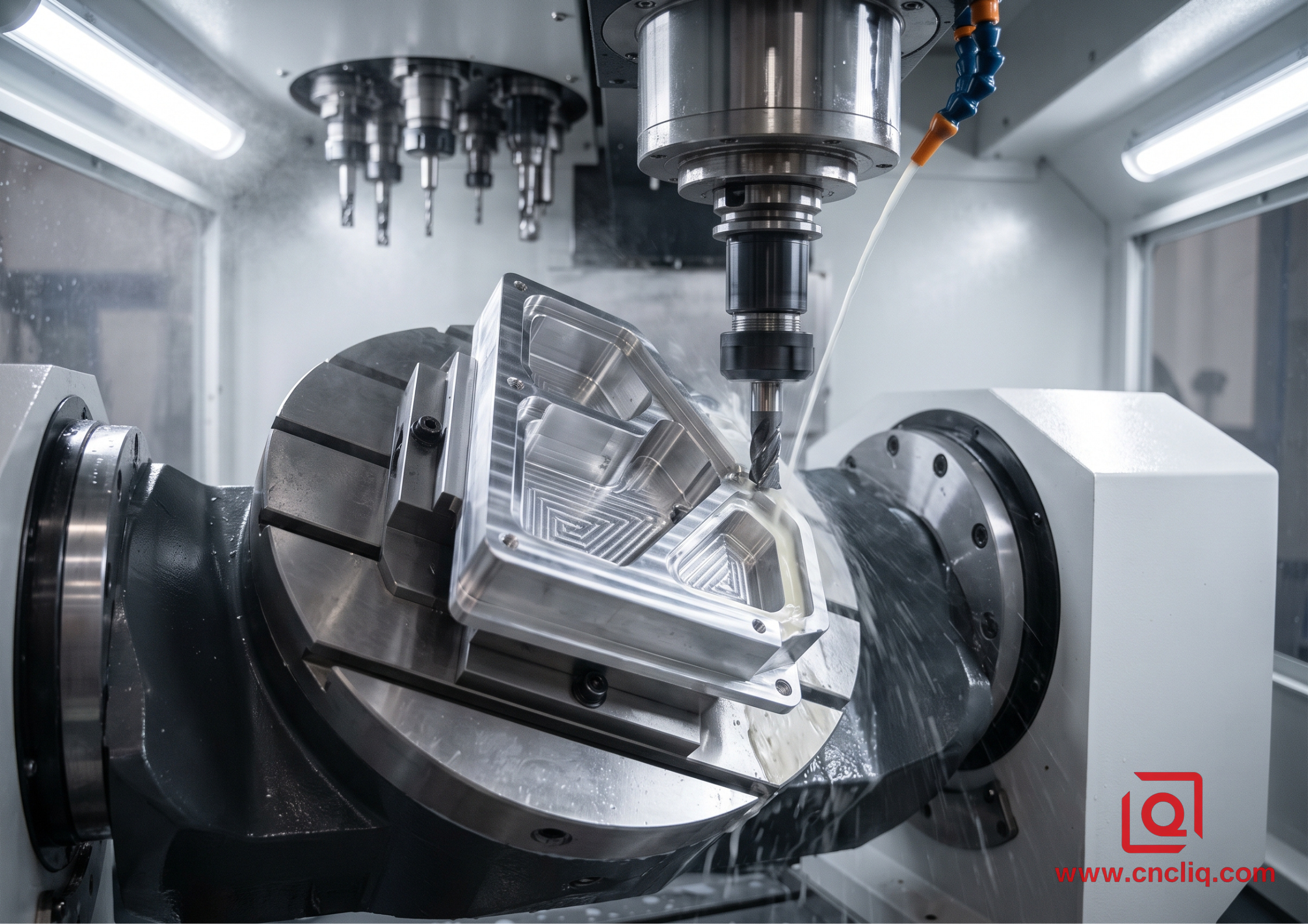
A true 5-axis machining center adds two rotational axes to standard linear motion. In a typical trunnion table configuration, the table tilts back and forth along the A-axis and rotates through a full 360 degrees along the C-axis.
5-Axis Dynamic Kinematics:
        [ Fixed Z-Spindle ]
                 |
                 v
        +-----------------+
        | Short, Rigid EM |
        +-----------------+
                 |
           +-----------+   <--- Tilting A-axis articulation
           | Workpiece |
           +-----------+   <--- Continuous rotating C-axis platform
For most precision aluminum enclosures and structural housings,the commercial value of 5-axis machining does not lie in cutting complex organic turbine blades. The primary advantage is 3+2 positional machining: orienting and cutting five full faces of a part in one single setup.
The Engineering Advantage: Short, Rigid Cutters
Every cutting tool acts as a cantilever beam. As the distance from the tool holder to the cutting tip increases, the tool becomes exponentially more flexible. Cutter deflection scales directly with the cube of the extended length:
-
Long reach on a 3-axis mill: When a deep cavity or tall vertical wall must be machined on a 3-axis machine, the tool must reach deep into the part. To avoid severe tool chatter, high-pitched resonance, and wavy surface steps, the machinist must slow spindle speeds down, take shallower radial cuts, and run passes slowly.
-
Tilted approach on a 5-axis mill: On a 5-axis setup, the trunnion table tilts the entire workpiece on an angle. The tool spindle clears the top edge of the part, allowing the operator to use a short, stubby cutter.The short tool maintains high rigidity, cuts at full speed without vibrating, and leaves a clean, uniform wall finish.
Extended Tool Reach (3-Axis Cavity):
|=== Tool Holder ===|==================== Extended Shank ====================> [Chatter & Deflection Risk]

Tilted Part Orientation (5-Axis Cavity):
|=== Tool Holder ===|==== Stubby Cutter ====> [High Rigidity & Stable Surface Finish]
Eliminating Manual Repositioning
Because a 5-axis machine presents multiple faces to the cutting tool in a single program,all critical holes, side ports, seal pockets, and mounting dowels share the exact same machine coordinate origin. Datum transfer error between sides is practically eliminated, protecting the tight positional relationships called out on the 2D drawing.
3. Mill-Turn Centers: The True "Done-in-One" Architecture
Mill-turn centers merge a high-speed lathe turning spindle with an overhead live-tool milling head and a synchronized secondary spindle. Instead of clamping a stationary part and rotating a tool, a mill-turn machine can rotate the workpiece, rotate the tool, or hold both in coordinated motion.
Synchronized Spindle Handoff:
[ Main Turning Spindle ] ===> Bar Stock Held ---> Turns Profile & Live Mills Cross Holes
                                                        |
                                                        v Synchronized dynamic pickup
[ Sub-Spindle Receiver ] <=== Precision Collet Pickup <-+ Cuts Off Stock & Finishes Backside
When an aluminum component is fundamentally cylindrical—such as a stepped sensor casing, valve body, threaded hydraulic manifold, or fluid sleeve with side ports—routing it through separate lathes and milling machines creates operational friction. Parts wait in shop bins between operations, chips collect in blind holes, and re-clamping adds concentricity error.
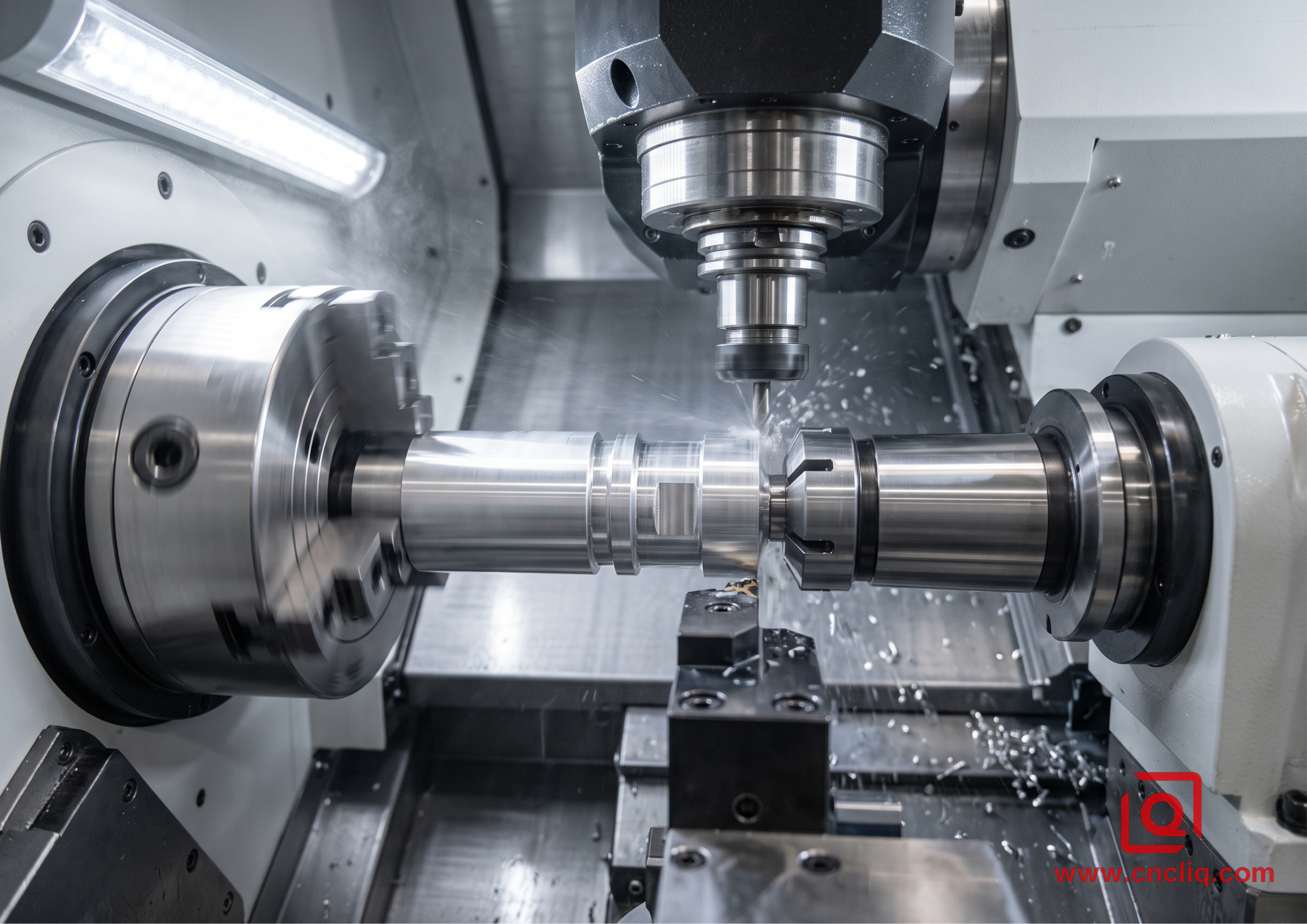
Mill-turn architecture addresses this through an integrated sequence:
-
The main spindle feeds raw aluminum bar stock, clamps it securely, and spins it for high-speed OD and ID turning.
-
The overhead milling head swings into position, locks the spindle at specific degree increments, and uses rotating live tools to mill flat wrench pads, drill cross-holes, and tap off-center patterns.
-
The sub-spindle advances toward the main spindle, matches rotational speed, and clamps onto the freshly turned front diameter using a smooth collet.
-
A parting tool slices the component free from the raw bar stock.
-
The sub-spindle retracts to face the back side, chamfer the rear bore, and mill back features, while the main spindle feeds out fresh stock to start the next part.
The entire component drops out into the parts catcher finished, with axial alignment between front and rear bores preserved.
4.Engineering Comparison: Process Capabilities Matrix
| Evaluation Parameter | 3-Axis CNC Milling | 5-Axis Machining | Twin-Spindle Mill-Turn Center |
| Typical Geometric Fit | Flat plates, single-plane profiles, open pockets | Multi-sided prismatic housings, undercut pockets | Turned round bodies with cross-holes and flats |
| Common Workholding | Kurt vises, soft jaws, clamp down plates | Self-centering vises, dovetail grip stock | Hydraulic chucks, bar pullers, precision collets |
| Setups for a 6-Sided Part | 2 to 4 manual flips | 1 to 2 setups total | 1 setup (done-in-one with sub-spindle) |
| Feature True Position | Dependent on manual locating repeatability | Held within a single coordinate datum frame | Concentricity locked across single machine run |
| Tool Length Strategy | Requires long-reach tools for tall features | Tilts part to use short, rigid tools | Short turning tools and rigid live milling heads |
| Surface Finish Consistency | Tool mismatch lines possible across flips | Uniform surface blend across angled faces | Single-point turned OD/ID, uniform milled flats |
| Setup & Programming Overhead | Low to moderate programming overhead | High (requires 3D collision check simulation) | High setup time,highly efficient once running |
| Ideal Batch Volume | Prototypes to medium production batches | Complex prototypes to recurring batch runs | Medium to high volumes, continuous bar-fed runs |
5. Shop Floor Case Study: Optical Housing for an Autonomous Sensor
A practical look at a custom sensor housing illustrates how matching component geometry to machine kinematics changes outcomes.
The Part and the Functional Requirements
An overseas engineering firm developed a 6061-T6 aluminum optical barrel for an outdoor sensing system. The cylindrical housing carried critical functional features:
-
A central precision-turned optical bore for lens assembly.
-
Four perimeter rectangular connector cutouts spaced at 90-degree intervals around the outer cylinder wall.
-
A rear face-seal groove intended to seat an elastomeric O-ring against moisture ingress.
-
A requirement that the outer connector cutouts remain tightly aligned relative to the central bore axis to prevent pin misalignment during harness assembly.
Original Multi-Machine Flow:
[Lathe: Turn Bore] --> Manual Transfer --> [VMC: 4th-Axis Rotary Index] --> Manual Transfer --> [VMC: Flip for Seal Groove]
* Three independent setups, operator intervention at each stage, risk of handling scratches on seal faces.
The Initial Manufacturing Approach: 3 Separate Operations
The original manufacturing plan split production across three separate pieces of equipment:
-
Operation 10 (CNC Lathe): Turn the raw aluminum billet, rough the outer diameter, and bore out the inner optical cavity.
-
Operation 20 (3-Axis Mill with Rotary Indexer): Mount the turned part onto an expanding arbor on a 4th-axis rotary unit. Index the part four times to cut the side connector ports and drill cross-holes.
-
Operation 30 (3-Axis Mill): Manually flip the component into soft jaws to face off the back end and mill the circular O-ring face seal groove.
Shop Floor Difficulties
Under this multi-machine workflow, quality inspection encountered persistent issues:
-
Datum Drift: When transferring the part from the lathe arbor to the milling soft jaws, small chips and manual clamping variance caused the connector cutouts to drift out of true position relative to the main optical bore.
-
Handling Damage: Moving aluminum parts across three separate machines increased handling marks and light scratches on the back sealing face, causing air-seal failures during bench testing.
-
Production Stagnation: Parts spent long periods sitting in holding bins waiting for available machine time between operations, requiring direct operator attention at every transfer step.
Consolidated Mill-Turn Flow:
[Main Spindle: Bar Stock Feed]
  --> Single-point turn inner bore & outer profile
  --> Live tool head mills 4 side connector windows using C-axis indexing
  --> Sub-spindle matches RPM, grabs finished OD with smooth brass collets
  --> Part-off tool separates finished component from raw bar
[Sub-Spindle: Retract & Finish]
  --> Face rear end flat and turn O-ring groove in single pass
* Zero manual re-handling, continuous cycle, consistent datum reference.
The Mill-Turn Solution
The routing was consolidated into a twin-spindle mill-turn center fed directly by extruded aluminum round bar stock:
-
Main Spindle Turning: The bar feeder advances the stock into the main chuck. Rigid boring bars rough and finish the critical inner optical cavity in a single continuous pass, ensuring roundness and a smooth internal bore.
-
Live Tool Milling: With the main spindle acting as a fully controlled indexing axis, an overhead live-tool milling head mills out all four rectangular connector cutouts, chamfers the edges, and drills the mounting holes.
-
Synchronized Sub-Spindle Transfer: The secondary spindle advances, matches rotation, and clamps onto the finished outer diameter using soft brass collets that protect the aluminum surface. The parting tool slices the component cleanly off the stock bar.
-
Back-Side Finishing: The sub-spindle retracts to face the back shoulder flat and turn the O-ring groove with a single-point tool.
Shop Floor Results
-
Handling Eliminated: Human interaction during the machining cycle dropped to loading raw bar stock and inspecting finished parts.
-
Geometric Stability: Because the inner bore, outer cutouts, and rear sealing groove were turned and indexed on a shared kinematic platform, datum drift was eliminated. Connector cutouts stayed aligned to the optical center.
-
Surface Integrity: Handling marks disappeared from the rear face, and the smooth single-point turned groove passed pressure testing reliably.
-
Overall Lead Time: Part processing became continuous.Rather than waiting between operations in shop bins, completed parts dropped straight out of the secondary spindle ready for deburring and surface finishing.
6. Practical DFM Rules for Designing Custom Aluminum Parts
When preparing 3D CAD models and 2D engineering drawings for manufacturing review, practical adjustments can help align designs with machine capabilities:
-
Identify True Position Requirements Across Faces: If your part calls for tight positional relationships or concentricity between features across three or more faces, communicate this early. Attempting to machine these parts on a 3-axis mill to reduce hourly machine rates often leads to scrap and dedicated fixture costs. Parts with multi-face tolerances benefit from 5-axis or mill-turn setups.
-
Evaluate Deep Pocket Corners: Internal vertical pocket corners must match a rotating cutter radius. If a pocket is deep and the corner radius is narrow, a 3-axis mill must use a long, slender cutter that is prone to vibrating. Increasing internal corner radii allows the shop to use thicker, stiffer tools, or avoid routing the part to an expensive machine simply to clear tight corners.
-
Examine the Part Core for Turning Symmetry: If a substantial portion of the part envelope is round, stepped, or hollowed along a central axis, it should be evaluated for mill-turn machining. Even prismatic components with square external dimensions can often be turned and live-milled from bar stock more efficiently than hogging a large billet from solid plate.
-
Manage Aluminum Internal Stress: Thick rolled aluminum plates carry internal residual stress from the rolling and heat treatment processes. When large pockets are milled out of one side of a plate, the balance of internal stress changes, causing the component to bow slightly when released from the vise. For thin-walled or asymmetrical parts, specify stress-relieved plate stock (such as 6061-T651) or plan a process flow that includes roughing, unclamping to relax stress, and finish machining.
FAQs
Q1: How do I know if my aluminum part actually requires 5-axis machining instead of a cheaper 3-axis setup?
Check your datum callouts and deep cavity profiles. If the print links features across 3 or more faces with true position limits under 0.03 mm, a 3-axis mill forces multiple manual flips—stacking fixture error every time. One setup on a 5-axis table cuts that risk entirely. Next, look at deep pockets: if depth exceeds 4 times the corner radius, 3-axis cutting demands long, spindly end mills that chatter and deflect. Tilt that workpiece on a 5-axis trunnion, and a stubby, rigid end mill hits full depth at speed without gouging wall finishes.
Q2: Why is 6061-T651 preferred over standard 6061-T6 for complex, thin-walled milled parts?
It boils down to the "51" temper code.After solution heat treatment, the mill mechanically stretches the plate by 1% to 3% to pull out erratic internal stresses. Standard T6 holds trapped tension inside the skin. Hog out thin webs, deep pockets, or uneven walls from plain T6, and the part will potato-chip the second you unclamp the vise. Ordering 6061-T651 keeps the raw stock flat, predictable, and stable all the way through aggressive roughing.
Q3: When does a mill-turn center become more cost-effective than running separate CNC lathe and mill operations?
A mill-turn center wins the moment a round or cylindrical part requires cross-drilled fluid passages, radial bolt patterns, or milled flats that must align accurately with internal turned bores. On separate machines, you pay for dual CAM setups, custom milling soft jaws to hold a round body, manual deburring between stations, and operator loading time for every cycle, whereas a twin-spindle mill-turn feeds continuous round bar stock, turns, live-mills, transfers to the sub-spindle dynamically, and drops a completed part into the bin every few minutes without handling damage.
Q4: Can tight tolerances achieved on the CNC machine be preserved through sulfuric acid anodizing?
Yes, but only if the machine shop and engineering team calculate chemical surface growth and etch-loss into the pre-machining dimensions before cutting metal. Standard Type II sulfuric anodizing typically penetrates 50% into the aluminum substrate and builds outward by 50% (adding roughly 0.010 mm to 0.015 mm per surface, which shrinks a finished bore diameter by 0.020 mm to 0.030 mm), while Type III hardcoat builds up even thicker; precision bearing bores and fine pitch threads must therefore be cut intentionally oversized or plugged with custom rubber masks prior to dipping into the chemical bath.
Q5: What is the most common CAD/DFM mistake that unnecessarily inflates aluminum CNC cycle times?
Designing square internal pocket corners that go all the way down to the floor is the single fastest way to drive up manufacturing costs. Because a milling tool rotates, it cannot cut a sharp 90-degree internal vertical corner; trying to get close forces the shop to run secondary micro-diameter end mills with tiny step-downs, or set up an electrical discharge machining (EDM) sinker burn just to clear material that could easily be avoided by allowing an internal fillet radius at least 1 mm larger than standard milling tool diameters.
Summary: Matching Part Geometry to Machine Capabilities
No single CNC machine configuration is best for every custom aluminum component.
-
3-Axis vertical machining centers provide an economical foundation for flat plates, single-sided brackets, and aggressive pocket roughing where parts are held in standard vises.
-
5-Axis machines excel on multi-sided housings and complex prismatic parts, using tilted orientations to reach deep areas with short, rigid cutters while holding tight tolerances across multiple faces.
-
Twin-spindle mill-turn centers offer an efficient solution for cylindrical parts with cross-features, completing turned and milled geometry in a single, continuous operation.
Reviewing your component's geometric profile, tolerance callouts, and batch quantities against machine capabilities early in the process ensures smooth production, consistent part quality, and reliable project economics.
Contact Information
Disclaimer
All technical articles, material specifications, machining recommendations, and surface treatment details published on this blog are for informational and reference purposes only. Please note that general blog insights do not replace signed technical agreements. Because custom parts vary by material heat numbers, machine calibrations, and specific tolerances, binding quality specs are governed solely by your approved CAD drawings, signed contracts, and formal quality plans.
All customer case studies featured on this blog have been thoroughly anonymized and sanitized.The performance metrics, manufacturing workflows, and imagery displayed serve solely to demonstrate our custom machining capabilities and do not represent a single universal standard for all orders.
Liqin Manufacturing Team
Built on 18 years of precision engineering experience, Ningbo Liqin Industry manufactures high-tolerance metal components for demanding global markets. We operate out of a 6,500 m² production hub equipped with over 150 machines, running 4-axis and 5-axis CNC machining, mill-turn machining, cold extrusion, and pressure die casting under one roof. This setup allows us to manage projects seamlessly, taking parts from initial CAD concepts directly to finalized shipments.
We handle quality control with zero compromise. We treat tight tolerances with the engineering discipline they require. Backed by ISO 9001, ISO 13485, and IATF 16949 certifications, our QA engineers run strict IPQC, FQC, and OQC checks on every single production batch. From CMM dimensional mapping and optical profiling to hardness and salt-spray testing, we validate your critical specs upfront—so you receive drop-in ready components with zero assembly headaches or costly line stoppages.On top of manufacturing, you can rely on us for two-hour response times on new RFQs, direct support for prototype sampling, and smooth export shipping across Europe, North America, Asia, and Oceania.
Welcome your inquiries and samples.Visit our website or contact us directly for a competitive quote!
