 English




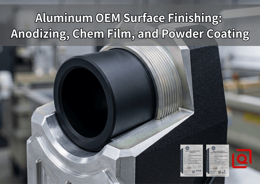
Nailing Ra 0.8 on an aluminum part straight off the 5-axis spindle is just step one. If your surface treatment gives out during field trials, holding a tight ±0.015 tolerance counts for nothing.
Surface treatments protect the substrate, preserve dimensional integrity, and deliver specific functional characteristics like dialectric breakdown resistance or conductive grounding. Yet, miscommunication between OEM engineering teams and surface finishing lines happens every day on manufacturing floors.
Let us skip the generic chemistry textbook talk. Below is how we actually handle anodizing, chem film passivation, and powder coating on the floor to prevent scrap and protect critical part interfaces.
1. Anodizing: Managing the 50/50 Dimensional Growth Rule
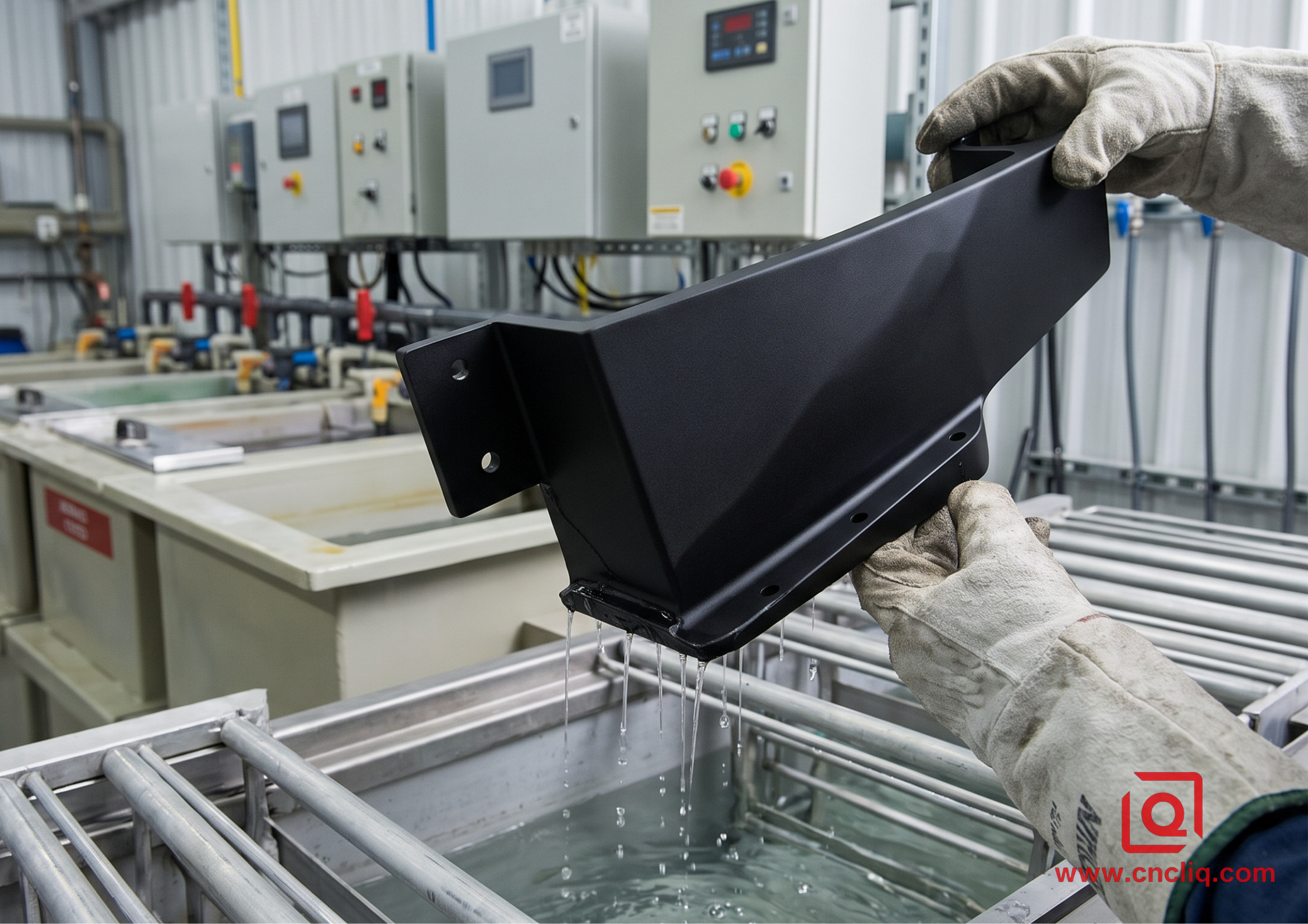
Most print errors we catch on incoming customer CAD models trace back to plating allowance oversights. Unlike paint, anodizing doesn't just sit on top. It’s an electrochemical reaction that converts the base aluminum directly into an Al2O3 ceramic skin.
If you just need baseline rust protection or a clean color finish, MIL-A-8625 Type 2 (Class 1 Clear / Class 2 Dyed) yields a 10 to 25 micron shell. Step up to severe service—sliding dielectric loads, heavy abrasion, or surviving 1000 hours in the salt booth—and you flag MIL-A-8625 Type 3 Hardcoat on the print.
             ┌─────────────────────────┐ ◄── Final Dimension (+12.5 microns/side)
             │   Coating Build-up      │     (50% Outward Growth)
─────────────┼─────────────────────────┼─ ◄── Pre-Machined Part Boundary
             │   Oxide Penetration     │     (50% Inward Penetration)
             └─────────────────────────┘
                   Base Aluminum Matrix (Substrate)
The fundamental mechanical rule to remember is the 50/50 penetration-to-growth ratio:
-
Approximately 50% of the coating thickness builds outward onto the surface.
-
The remaining 50% penetrates inward, consuming the aluminum substrate.
If your drawing calls out a 50 micron Type 3 Hardcoat layer, your external shaft diameter expands by 25 microns per side, which increases the total outside diameter by 50 microns. Meanwhile, an internal bore shrinks by 50 microns across the diameter.
Shop-Floor Checklist for Anodizing Callouts:
-
State whether drawing dimensions apply before plating (pre-plate) or after final coating (post-plate).
-
For small threaded blind holes (M3, M4, M5), specify silicone masking plugs prior to racking. Otherwise, heavy oxide buildup alters thread pitch diameters and snaps fasteners during final assembly.
-
Keep current densities stable at 2.5 to 3.5 A/dm2 in a sulfuric acid bath maintained between 0 and 4 degrees Celsius for dense, wear-resistant cell structures.
2. Chemical Conversion: Conductive Corrosion Defense
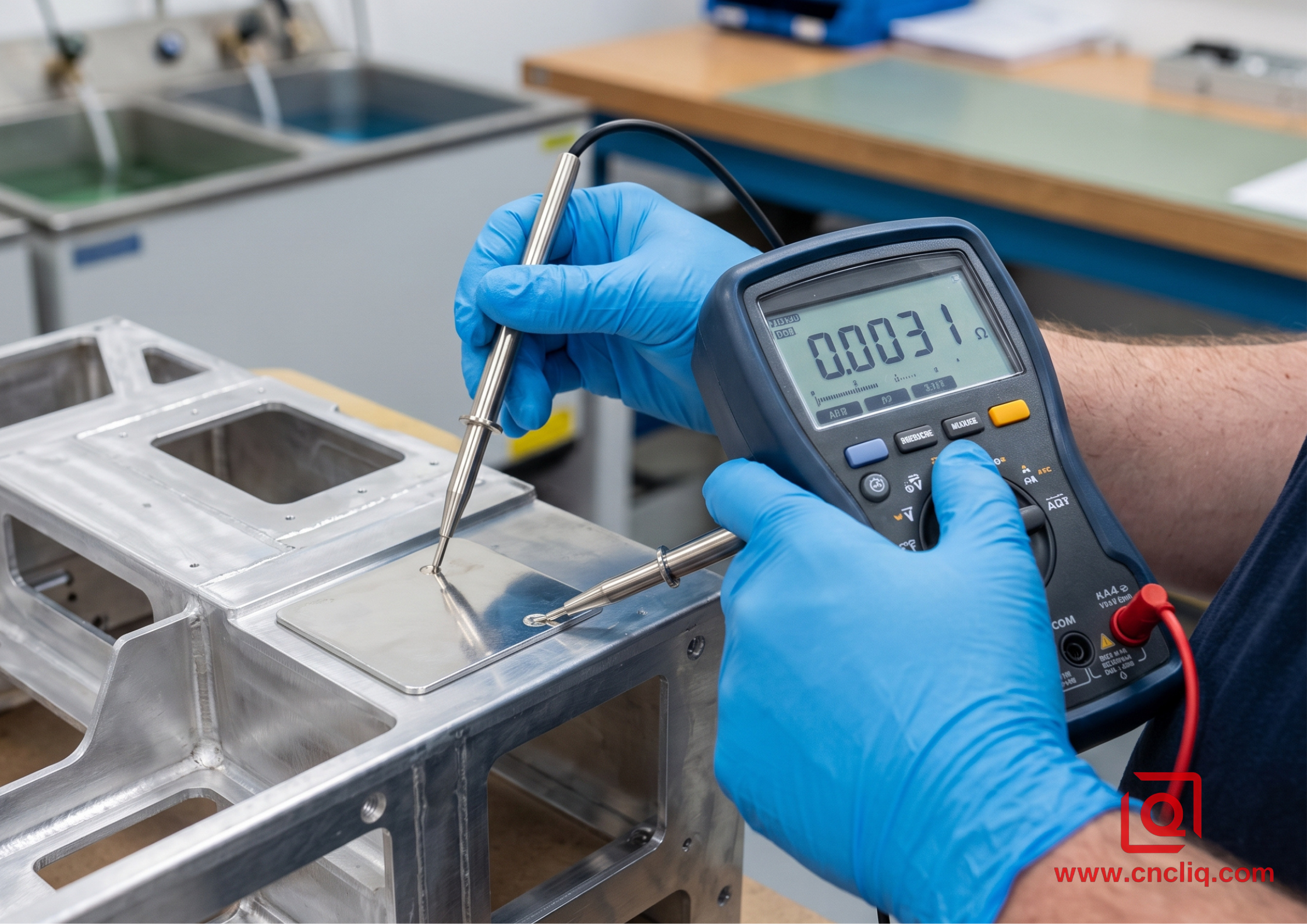
When a customer needs corrosion protection without losing electrical continuity—such as for RF shielding enclosures, communication chassis, or ground lug interfaces—anodizing is off the table because anodized layers are non-conductive insulators. Here, we switch to chemical conversion coatings, universally governed by MIL-DTL-5541.
                   Passivation & Conversion Workflow
┌────────────────┐     ┌────────────────┐     ┌────────────────┐     ┌────────────────┐
│ Alkaline Degrease│ ──► │ Acid Deoxidize │ ──► │ Chem Film Bath │ ──► │ DI Water Rinse │
│ (55-65°C, 3 min)│     │ (Desmut Stage) │     │ (Type 2 TCP)   │     │ (<40°C Warm Air)│
└────────────────┘     └────────────────┘     └────────────────┘     └────────────────┘
Modern environmental compliance mandates MIL-DTL-5541 Type 2 (Hexavalent Chromium-Free) chemistries, utilizing trivalent chromium complexes (TCP).
-
Class 1A: Thick protective barrier formulated for maximum corrosion resistance on bare metal substrates. It also works well as a paint adhesion base, easily handling 336 hours of ASTM B117 salt spray testing.
-
Class 3: A thinner conversion film engineered specifically for low electrical contact resistance. It stays well below the standard 5000 micro-ohms per square inch threshold under 200 psi contact load.
Because trivalent passivate adds less than 1.0 micron of thickness, it creates zero functional change on critical bearing fits or fine-pitch external threads.
3. Industrial Powder Coating: Impact Strength & Environmental Sealing
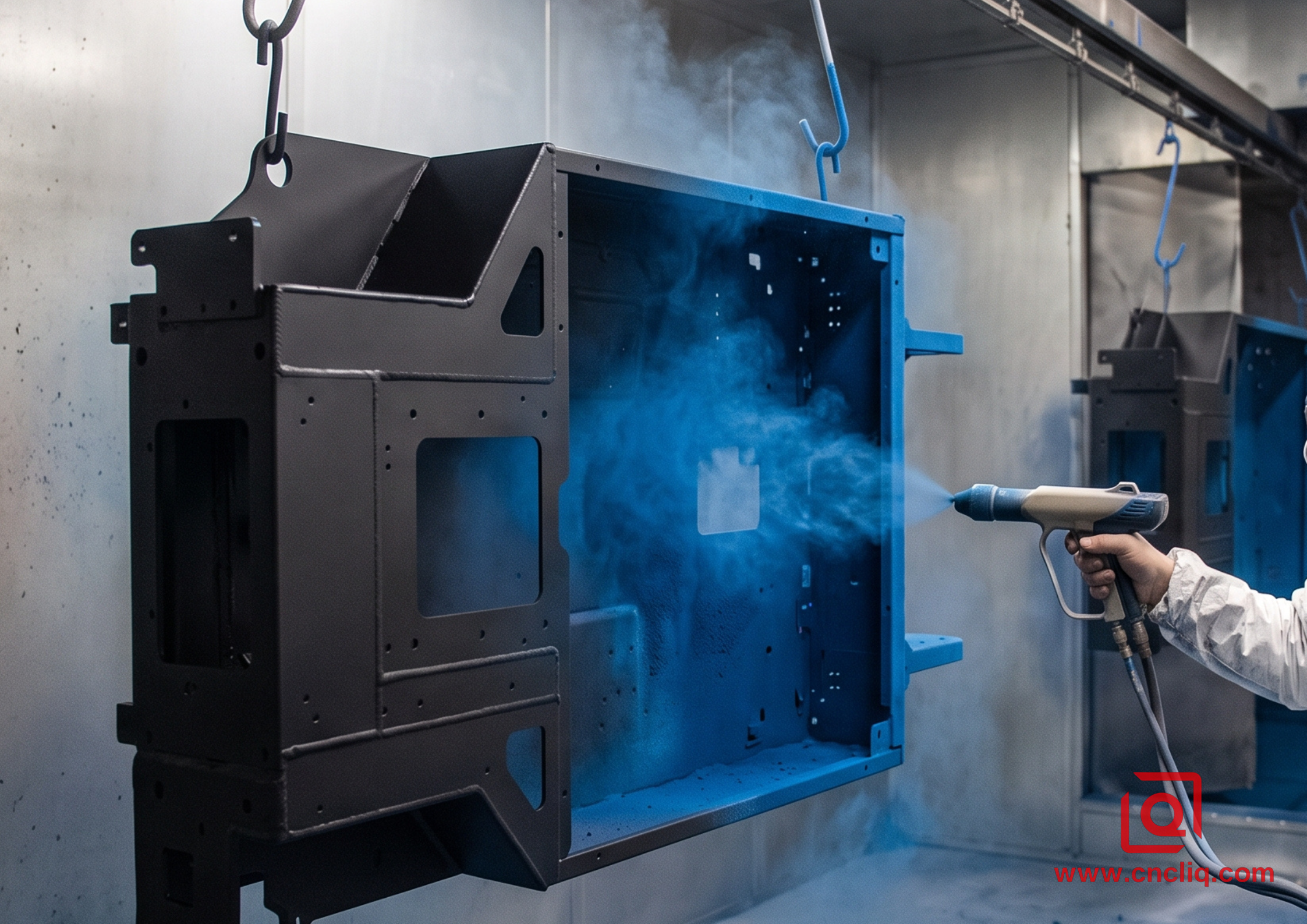
Put liquid wet-spray on heavy brackets, exposed telecom enclosures, or robot chassis, and it flakes off fast under UV burn, flying gravel, and washdown chemicals. Powder coat them electrostatically instead—you get a resilient polymer armor baked on at 60 to 120 microns.
The key to long-term powder coat adhesion is surface prep. Applying powder directly over a raw, smooth, as-machined aluminum surface is a recipe for flaking and delamination under thermal cycling.
                               Cross-Hatch Adhesion
           Raw Aluminum Surface                  With Pre-Treatment Primer
        ┌────────────────────────┐              ┌────────────────────────┐
        │  Powder Coat Polymer   │              │  Powder Coat Polymer   │
        ├────────────────────────┤              ├────────────────────────┤
        │ ░░░ Weak Bond Line ░░░ │              │ ▓▓ Chromate Base TCP ▓▓ │
        └────────────────────────┘              └────────────────────────┘
          Substrate: Bare Al 6061                 Substrate: Etched Al 6061
To guarantee an ASTM D3359 Method B Class 5B cross-hatch rating, parts run through a three-stage bath sequence: alkaline degreasing, acid etching to remove natural surface oxides, and a light conversion coating base before electrostatically applying the powder. Once sprayed, parts cure in an infrared or convection oven at 180 to 200 degrees Celsius for 15 to 20 minutes to cross-link the resin matrix.
Technical Comparison Table
| Processing Method | Primary Industry Standard | Typical Film Build Thickness | Electrical Conductivity | Salt Fog Resistance (ASTM B117) | Typical Application Scope |
| Type 2 Anodize | MIL-A-8625, Type 2, Class 1/2 | 10 to 25 microns | Insulative (> 10000000000 ohms) | 240 to 336 Hours | Medical housings, drone frames, brackets |
| Type 3 Hardcoat | MIL-A-8625, Type 3, Class 1/2 | 35 to 65 microns | High Dielectric (> 1000 V) | 336 to 1000+ Hours | Hydraulic pistons, drive sprockets, sliding rails |
| Chem Film (TCP) | MIL-DTL-5541F, Type 2, Class 3 | 0.2 to 0.8 microns | Conductive (< 0.005 ohms/sq.in) | 168 to 336 Hours | RF filter boxes, avionics enclosures |
| Powder Coating | AAMA 2604 / Qualicoat Class 2 | 60 to 120 microns | Non-Conductive | 1000 to 3000 Hours | EV charging cabinets, outdoor enclosures |
Real-World Case: Solving Masking Bleed on a Drone Sensor Chassis
A Tier-1 commercial drone client approached us with a high-density aluminum 6061-T6 sensor chassis. The engineering drawing required two competing properties on a single monolithic part:
┌────────────────────────────────────────────────────────┐
│               Drone Sensor Chassis Overview             │
│                                                        │
│   ┌───────────────┐                  ┌───────────────┐ │
│   │ External Body │                  │ Internal Cav. │ │
│   │ Black Type 3  │                  │ Class 3 TCP   │ │
│   │ 45 micron Hard│                  │ Conductive    │ │
│   └───────┬───────┘                  └───────┬───────┘ │
│           │                                  │         │
│           ▼                                  ▼         │
│   Wear & Weather Prep                Grounding Path    │
└────────────────────────────────────────────────────────┘
-
Exterior Faces: Black MIL-A-8625 Type 3 Hardcoat (45 to 50 microns target) for abrasion defense and low visual reflectivity.
-
Interior Cavity & Grounding Bosses: MIL-DTL-5541 Type 2 Class 3 trivalent chem film for EMI/RFI shielding, with surface resistance strictly under 0.010 ohms across mating surfaces.
Project Challenge: Acid Creep During Chemical Processing
Standard masking tapes consistently failed at the transition line under the thermal and chemical stresses of the cold anodizing bath. The aggressive sulfuric acid electrolyte seeped past conventional tape borders, leaving uneven edge burns and destroying conductivity on the internal grounding pads.
       Masking Failure Mechanism vs. Custom Step-Plug Solution

    [Standard Tape Application]            [Custom EPDM Step-Plug]
         Acid Bath Intrusion                   Sealed Contact Lip
              │     │                              │        │
              ▼     ▼                              ▼        ▼
       ┌───┐ tape ┌───┐                      ┌────────────────────┐
       │   └──────┘   │                      │▓▓▓ EPDM PLUG ▓▓▓▓▓▓│
       │  Acid Bleed  │                      │ ╔════════════════╗ │
       │  (Corrodes)  │                      │ ║ Positive Seal  ║ │
       └──────────────┘                      └─╨────────────────╨─┘
The Engineering Solution:
-
We designed custom-molded high-durometer EPDM step-plugs that seal against internal bearing ledges with positive interference.
-
We sequenced the surface treatment order: first, we immersed the entire raw machined part in a MIL-DTL-5541 Type 2 bath, applying the thin conductive conversion coat across all faces.
-
After drying, the custom plugs were inserted into internal bores and electrical interfaces.
-
The exposed outer frame went through sulfuric anodizing at 1.8 A/dm2 with temperature strictly controlled at 2 degrees Celsius, building up a 45 micron hard oxide shell.
-
The plugs were removed, followed by a warm DI water rinse at 38 degrees Celsius.
                   Final Processing Verification
┌─────────────────────────┐             ┌─────────────────────────┐
│ External Hardcoat Check │             │ Ground Pad Conductivity │
│ Target: 45 to 50 microns│             │ Target: < 0.010 ohms    │
│ Result: 47.4 microns    │             │ Result: 0.0032 ohms     │
└─────────────────────────┘             └─────────────────────────┘
The resulting parts showed zero acid-bleed line defects across all manufacturing lots. Exterior surfaces met 60 HRC equivalent surface hardness, while interior grounding pads recorded surface resistances between 0.0028 and 0.0041 ohms.
4 Practical Rules for Your Next Aluminum OEM Drawing
-
State Tolerances Post-Coating Explicitly: If a bore is machined to 20.000 mm (+0.010/-0.000 mm) and then receives a 40 micron Type 3 hardcoat without pre-plate allowance, the pin will not fit during assembly.
-
Watch Racking Contact Points: Anodizing requires electrical contact on the part via titanium or aluminum racks. Always identify acceptable racking touch locations on the print where a 1 to 2 mm un-anodized contact spot will not impact fit or cosmetics.
- Watch out for sharp corner spalling: Raw outside corners under 0.5 mm radius draw wild, brittle oxide growth during hardcoat. Break those edges with a 0.5 to 1.0 mm chamfer or fillet so the skin won’t chip out.
- Purge blind holes on the powder rack: Air pocketed deep inside unvented holes pops when the shell hits the 200 degrees Celsius oven, spitting pinholes and crater pits right into your cured coat. Add through-holes or call out silicone plug masking for all blind tapped features.
FAQs
Q1: How does material grade swing the final look and coat quality in Type 2 anodizing?
A: Chemistry runs the show here. 6061-T6 delivers a clean, matte luster because the magnesium and silicon stay in check. Shift to high-yield 7075, and that 6 percent zinc payload bleeds a subtle bronze cast—meaning your dip tanks must hold strict temp and chemistry, particularly for jet-black runs. Cast grades like A380 or ADC12 sit above 8 percent silicon; plunge them in sulfuric acid, and they turn out blotchy grey or soot-stained. You skip anodizing on those and head straight for chem film or powder.
Q2: Can we shoot powder straight onto anodized or chem-filmed aluminum?
A: Spraying right over a MIL-DTL-5541 Type 2 chem film (trivalent conversion) base is standard shop routine for seaworthy and outdoor enclosures. The thin conversion layer acts as an active corrosion barrier and increases cross-hatch adhesion. However, powder coating over thick Type 3 hardcoat is not recommended. The brittle, micro-cracked ceramic structure of hard anodize can outgas during the 180 to 200 degrees Celsius oven cure, causing surface blisters and micro-pinholes in the powder coat.
Q3: How do we specify masking callouts for tight-tolerance dowel pin holes and bearing bores?
A: Always provide a dedicated masking print callout marking the exact hole IDs, mating faces, and ground pads. Call out clearly whether your tolerances hold before or after plating. For pin bores locked inside 0.010 mm, flag high-temp silicone pull-plugs through anodize or powder setups to keep the bare metal clean. If that ID still needs rust protection, write up a staged process: dip the entire part in MIL-DTL-5541 Class 3 chem film first, plug the hole tight with silicone, then route it through the final anodizing or powder booth.
Q4: Why does color tone drift from one dyed anodizing batch to the next?
A: Locking in color across repeated CNC runs comes down to three floor controls: tank temp (pegged within ±1 degree Celsius), dye bath pH (held tight at 5.5 to 6.0), and raw material heat lots. Parts machined from distinct raw billet heats will react differently during the initial acid etch phase. To avoid color mismatch on multi-part assemblies, machine mating visual components from the same raw material lot and run them through the anodizing and dye tanks in identical rack loads.
Q5: How does pre-anodize bead blasting mess with part tolerances and surface finish?
A: Hitting parts with 120-grit glass bead knocks down milling tool paths, leveling an Ra 1.6 machined face into a flat, omnidirectional Ra 0.8 matte finish. But hammering the surface takes off 3 to 8 microns of raw stock and dulls crisp corners. If you've got razor edges or tight snap-ring lands, mask them off with custom tooling beforehand or choke nozzle pressure under 40 psi.
Summary
Milling tight tolerances is just half the battle on custom aluminum OEM hardware; nailing your secondary finishing decides whether parts actually mate, conduct current, and survive out in the wild. Once you dial in the 50/50 penetration-to-growth split on MIL-A-8625 Type 2 and 3 hardcoat, drop in MIL-DTL-5541 conversion coats for chassis grounding and EMI protection, and run proper chemical preps before powder hits the metal, you close the split between blueprint numbers and real shop-floor output—keeping scrap bins empty and assemblies moving.
Contact Information
Disclaimer
All technical articles, material specifications, machining recommendations, and surface treatment details published on this blog are for informational and reference purposes only. Please note that general blog insights do not replace signed technical agreements. Because custom parts vary by material heat numbers, machine calibrations, and specific tolerances, binding quality specs are governed solely by your approved CAD drawings, signed contracts, and formal quality plans.
All customer case studies featured on this blog have been thoroughly anonymized and sanitized. The performance metrics, manufacturing workflows, and imagery displayed serve solely to demonstrate our custom machining capabilities and do not represent a single universal standard for all orders.
Liqin Manufacturing Team
Built on 18 years of precision engineering experience, Ningbo Liqin Industry manufactures high-tolerance metal components for demanding global markets. We operate out of a 6,500 m² production hub equipped with over 150 machines, running 4-axis and 5-axis CNC machining, mill-turn machining, cold extrusion, and pressure die casting under one roof. This setup allows us to manage projects seamlessly, taking parts from initial CAD concepts directly to finalized shipments.
We handle quality control with zero compromise. We treat tight tolerances with the engineering discipline they require. Backed by ISO 9001, ISO 13485, and IATF 16949 certifications, our QA engineers run strict IPQC, FQC, and OQC checks on every single production batch. From CMM dimensional mapping and optical profiling to hardness and salt-spray testing, we validate your critical specs upfront—so you receive drop-in ready components with zero assembly headaches or costly line stoppages. On top of manufacturing, you can rely on us for two-hour response times on new RFQs, direct support for prototype sampling, and smooth export shipping across Europe, North America, Asia, and Oceania.
Welcome your inquiries and samples. Visit our website or contact us directly for a competitive quote!
