 English





If you pull an aluminum billet out of raw stock storage, mount it up, and hit the green button without dialing in your fixture strategy and cycle math first, you are already burning margin. Machining custom aluminum parts for OEM programs is rarely about whether a cut can be made. It is about how the geometry behaves once internal stresses relieve themselves, how many setups you can eliminate before runout stacks up, and matching the raw feature count to the right spindle configuration.
Take a blueprint into any actual shop bay. You will see 6061-T6 bar, plate, and custom extrusions moving between 3-axis beds, multi-axis trunnions, and live-tooled sub-spindles. Every setup change introduces human handling, datum transfer variance, and cycle lag.
Let us break down how we evaluate part geometries, configure tooling paths, and select the exact CNC machining process for custom aluminum OEM production.
1. Material Temper, Stress Relief, and the Realities of Aluminum Alloys
Before matching toolpaths to spindles, look at your raw billet. In OEM manufacturing, 90% of custom aluminum machining revolves around three distinct grades: 6061-T6, 7075-T6, and 5052-H32. Each cuts differently, dissipates heat differently, and shifts under residual stress differently.
Roughing pass -> Heat buildup -> Stress relief -> Part bowing -> Finish cut-off datum
To stop that chain reaction, temper selection and roughing-to-finishing balance matter as much as feeds and speeds
- 6061-T6 (The Workhorse): The yield strength sits near 276 MPa.It machines clean, shears into predictable curly chips under polished carbide, and takes Type II and Type III (hardcoat) anodizing with uniform cosmetic results. The catch? Heavy internal residual stresses from heat-treating. Hog out deep asymmetric cavities on a 3-axis mill, and your part will bow along the longitudinal axis by 0.20 mm or more the moment vises unclamp.
-
7075-T6 (High-Stress & Aerospace Grade): Yield strength jumps above 503 MPa. Zinc is the primary alloying element. It chips crisply, leaves glassy surface finishes, and holds thread engagement under severe torque. But it cuts stiffer, causes faster flank wear on end mills, and demands rigid setups to kill resonance chatter.
-
5052-H32 (Enclosures & Welded Housings): Magnesium-alloyed, non-heat treatable. Highly ductile. If you try to run high-speed finishing passes on deep 5052 cavities, chips stick to tool flutes. You get built-up edge (BUE) in minutes unless you run high-pressure through-spindle coolant and dedicated high-rake single-flute cutters.
2. 3-Axis CNC Milling: The Baseline for Prismatic Components
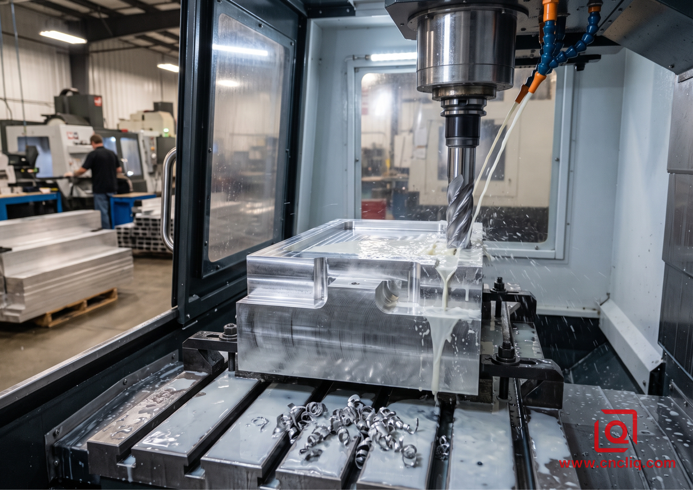
When your part design concentrates features along a single coordinate plane—mounting faces, parallel bores, perpendicular threaded holes, and stepped boundary contours—a standard vertical machining center (VMC) delivers the lowest hourly run cost.
Setup 1: Top face skimmed, perimeter profiled, blind pockets cleared.
Flip part manually.
Setup 2: Soft jaws clamped on profiled boundary. Bottom datum cut, mounting holes tapped.
The engineering boundary for 3-axis is not capability; it is setup accumulation. Every time an operator breaks a clamp, flips a block, and re-indicates an edge finder or Renishaw probe, you inject roughly ±0.015 mm of positional tolerance stack-up.
Best Fit For:
-
Heat sinks, bracket plates, flat manifolds, sensor mounting bases, structural chassis panels.
-
Features accessible from one or two parallel clamping directions.
-
Prototype-to-mid volumes where custom hydraulic fixture investment makes no financial sense.
3. 4-Axis Milling & Indexing: Tackling Radial Features Without Multi-Ops
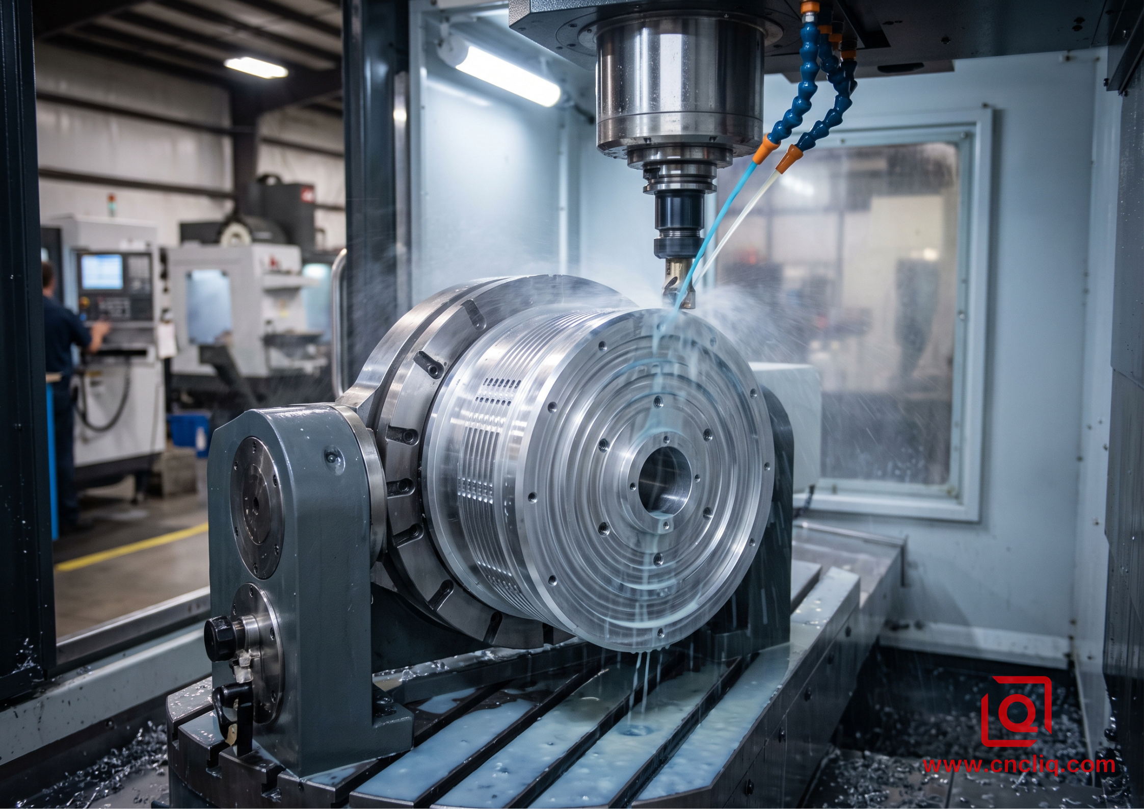
Add a rotary table (typically an A-axis tilting or rotating along the X-axis) to a 3-axis table, and your clearance envelope changes completely.
Instead of building 4 separate vise setups to drill, counterbore, and mill keyways around an aluminum cylinder or hexagonal housing, you chuck the billet into an indexing fixture. The tool approaches from continuous radial angles while maintaining a single primary datum.
-
Eliminates 3 to 5 separate operator interventions per run.
-
Keeps radial hole true position within 0.025 mm relative to the central bore axis.
-
Cuts setup times, letting you run lights-out shifts on medium batch sizes.
If your component has cross-holes, angled oil ports, or wrap-around perimeter cooling slots, moving from a pure 3-axis setup to 4-axis tombstone or rotary indexing drops unit costs by 18% to 30% through labor reduction alone.
4. 5-Axis Simultaneous & 3+2 Machining: Compound Angles and Deep Cavities
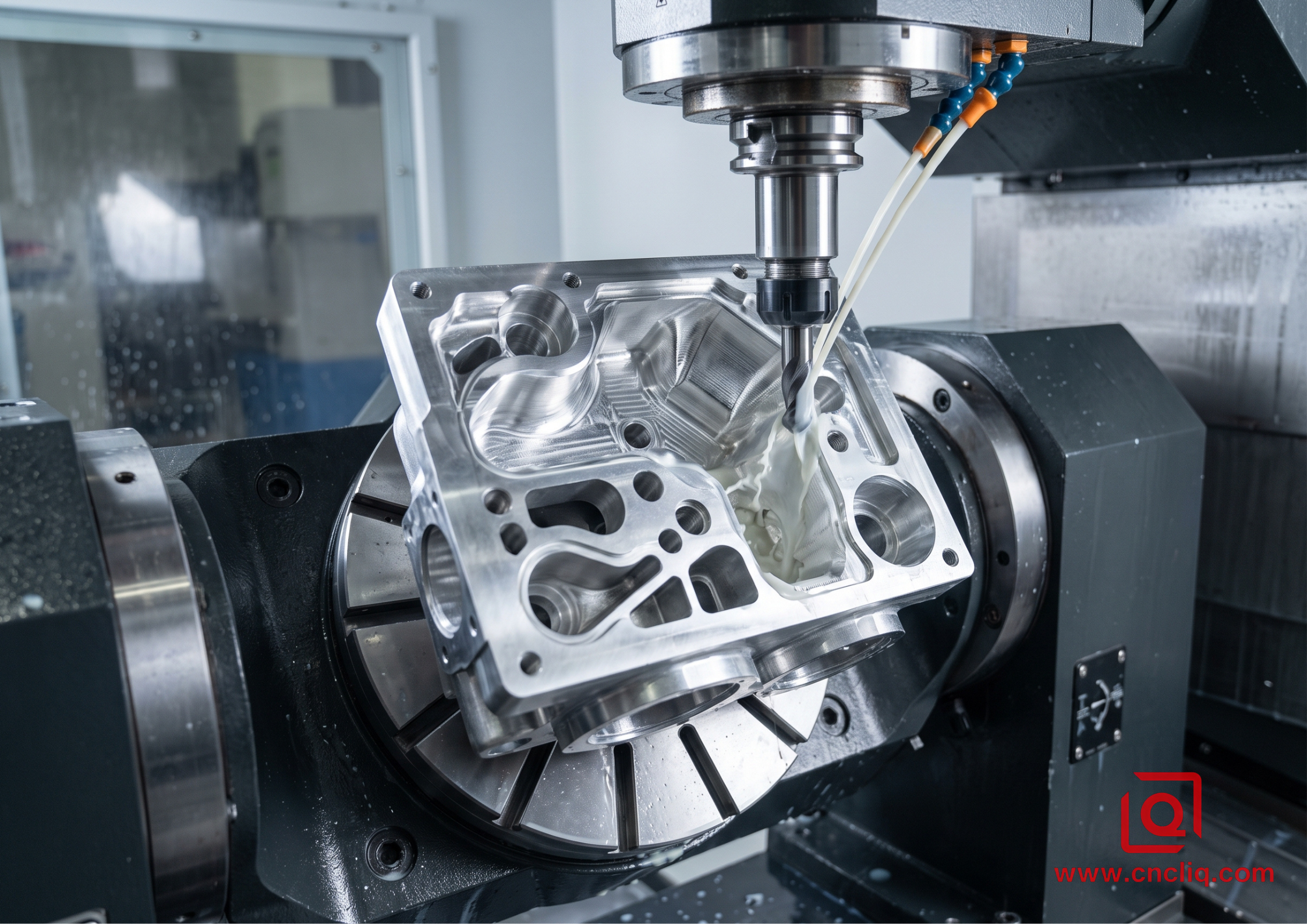
Do not buy into the assumption that 5-axis machining is exclusively for aerospace impellers or organic, sculptured surfaces.In production aluminum OEM manufacturing, 80% of our 5-axis cycle time uses 3+2 positional machining, not continuous simultaneous 5-axis motion.
Why 3+2 Positional Saves Jobs
Instead of flipping a complex aluminum manifold across six separate fixtures, a 5-axis trunnion indexes the workpiece into compound angles, locking axes mechanically. The cutting tool approaches faces at 30°, 45°, or compound compound compound orientations under maximum rigidity.
Long tool on 3-axis:  [=== Spindle ===]---------------> [Deep Pocket]  --> Deflection & Chatter
Short tool on 5-axis: [=== Spindle ===]-> / [Tilted Pocket]            --> Zero Deflection, 3x Feed
By tilting the part toward the spindle, you swap out an extended 150 mm necked-down end mill for a rigid 35 mm stub tool.The physics change instantly: tool deflection scales with the cube of overhang length (L³). A shorter cutter lets you triple your chip load, maintain Ra 0.8 µm sidewall finishes without chatter marks, and eliminate bench hand-finishing.
5-Axis Process Parameters & Engineering Thresholds
| Machining Attribute | 3-Axis VMC | 4-Axis Indexing | 5-Axis (3+2 & Simultaneous) |
| Typical Positional Tolerance | ±0.020 mm to ±0.050 mm | ±0.015 mm to ±0.030 mm | ±0.005 mm to ±0.012 mm |
| Surface Finish Capability (Ra) | 0.8 µm – 1.6 µm | 0.8 µm – 1.2 µm | 0.4 µm – 0.8 µm |
| Primary Fixturing Approach | Vises, soft jaws, toe clamps | 4th-axis chuck, tailstock, trunnion | Zero-point clamping, dovetail stock |
| Tool Length-to-Diameter Ratio | Up to 8:1 (high deflection risk) | Up to 6:1 | 3:1 or less (tilted clearance) |
| Setup Operations Needed | 3 to 6 handling steps | 1 to 2 handling steps | 1 to 2 handling steps ("Done-in-One") |
| Target OEM Part Geometry | Flat plates, prisms, simple enclosures | Shaft cross-features, cams, radial slots | Deep multi-face manifolds,thin-wall housings |
5.Mill-Turn Multi-Tasking: Symmetrical Geometry with Off-Axis Demands
When an aluminum OEM part starts life as round bar stock but ends up with cross-drilled bolt circles, off-center milling slots, and precision internal bearing races, running it through a standalone lathe and transferring it to a vertical mill introduces runout risk.
Lathe Turning (Bore & Outer Diameter) -> Unclamp -> Transfer -> Mill Setup -> Runout: 0.035 mm
Mill-Turn Center: Main spindle turns -> Live tooling mills -> Sub-spindle grabs -> Runout: 0.005 mm
Mill-turn centers equipped with driven live tooling (B-axis milling heads, C-axis spindle interpolation, and Y-axis travel) merge turning and milling into one enclosure.
-
High-pressure bar feeder feeds 6061-T6 round bar through the main spindle.
-
Turning inserts rough and finish OD/ID bearing fits down to ISO tolerance grade IT6 (within 0.008 mm).
-
The main spindle locks or interpolates as a rotary C-axis while 12,000 RPM live tools drop in from the turret to mill external flats, engrave identification codes, and tap blind holes.
-
A synchronized sub-spindle advances, clamps onto the finished outer diameter, parts off the stock with a carbide blade, and finishes the back face.
The finished part drops onto the parts-catcher conveyor every 90 seconds, complete.No operator hands, no secondary deburring, and total runout between front and rear features stays locked below 0.008 mm.
6. Industrial Application Case: Automotive Sensor Enclosure
An overseas Tier-1 automotive customer approached our engineering bay with a production bottleneck on a custom 6061-T6 aluminum radar sensor housing.
Customer Prototype Process (3 Separate Machines):
[3-Axis Roughing OP10] -> [3-Axis Cavity OP20] -> [Horizontal Tap OP30] -> CMM Fail Rate: 14%
The Engineering Problem:
-
Geometry: A deep interior shielding cavity, thin peripheral sealing walls (1.20 mm nominal), four radial M3 mounting holes, and a critical seal-groove flatness requirement of 0.015 mm across a 120 mm diagonal span.
-
Failure Mode: Under their legacy 3-axis process routing, clamping forces across three separate machine vises introduced elastic deformation during cutting. When the vise pressure released, the thin walls sprang outward, blowing the seal groove flatness out to 0.038 mm. Furthermore, datum transfer across operations caused the radial M3 holes to drift out of true position by 0.060 mm relative to the main cavity datum.
Raw Ticket -> Zero-Point Dovetail Prep -> 5-Axis (3+2 Roughing) -> Remaining 2 Hrs -> 5-Axis Finish Cut
Our Engineering Solution:
- Material Prep: A sacrificial 3.0 mm dovetail tab was added to the bottom of raw extruded 6061-T6 stock, held in a 5-axis pneumatic zero-point self-centering display.Clamping force localized entirely on the tab—zero side-wall compression.
-
Roughing Path: Hogged out the primary pocket at 14,000 RPM with a 12 mm 3-flute, DLC-coated carbide end mill. We dialed in a 12.0 mm axial cut depth (ap) and 1.8 mm stepover (ae), sticking to high-speed trochoidal milling to keep cutting pressure down.
-
Thermal Stabilization: Left 0.35 mm stock on all internal and external surfaces. Allowed the batch to rest in ambient coolant wash for 2 hours to normalize temperature and vent internal lattice stresses.
-
Finishing Pass: Indexed the trunnion table at 35° using 3+2 positioning. Ran a short 6 mm stub end mill with a corner radius of 0.2 mm, finishing the thin walls and the seal groove in a single continuous toolpath. The spindle tilted to clear the pocket rim without requiring excessive tool stick-out.
-
Back-Face Removal: Part transferred to a standard secondary 3-axis setup with custom polyurethane vacuum soft jaws to skim off the sacrificial dovetail tab.
The Measured Result:
-
Seal Groove Flatness: Brought down from 0.038 mm to a stable 0.009 mm, easily passing the 0.015 mm design spec.
-
Radial Hole True Position: Held consistently within 0.012 mm relative to primary cavity datums.
-
Scrap Rate: Dropped from 14.2% across three handling steps to 0.4% on the single-setup 5-axis line.
-
Total Cycle Time: Trimmed from 22.5 minutes combined across three machine benches to 8 minutes 40 seconds total spindle time.
7. DFM: Guidelines to Control Spindle Hours
Before finalizing your CAD models and sending out 2D prints for quoting, check these physical machining constraints. Adjusting these parameters on your CAD models will directly reduce machine cycle times and cut tool wear.
   Avoid Sharp Internal Corners             Use Graduated Cavity Depths
         | |                                        | |
      |  | |  |                                  |  | |  |
      |  |_|  |  <-- Tool chatters!              |   \_/  |  <-- Standard radius tools run fast!
      |_______|      (Requires tiny EDM/mills)   |________|      (Depth-to-width <= 4:1)
-
Inside Corner Radii (Rc): Always design internal pocket corners with a radius at least 10% to 15% larger than your target milling cutter radius. If you need a 10 mm pocket depth, do not call out an R3.00 mm corner (which forces a 6 mm cutter to bury into a 90° turn and squeal). Specify R3.50 mm or R4.00 mm. The cutter interpolates the corner smoothly without slowing down feed rates or leaving chatter marks.
-
Floor-to-Wall Transitions: Skip sharp 90° corners where cavity floors meet side walls. Throw in a small bottom blend radius (0.5 mm to 1.0 mm). That lets programming specify bull-nose mills, which hold up against edge chipping far better than square end mills when chips get thick.
-
Wall Thickness Limits: Hold free-standing vertical walls above 1.0 mm on structural parts, or 0.8 mm minimum on short local ribs. Go any thinner and the stock deflects off the flute under tool pressure, yielding tapered sides and forcing painful, slow spring passes just to hit size.
-
Hole Depth vs. Tap Tooling: Cap blind tapped holes at 2.5 times nominal pitch diameter (2.5 x D).Specifying an M4 thread 18 mm deep adds zero pull-out strength in 6061-T6; you just pack flutes with chips, snap taps, and drag out run times.
-
Standardized Tool Profiles: For undercuts, seal grooves, or edge breaks, check your geometry against catalog tool inserts. Drawing an oddball 37° bevel or proprietary dovetail width forces us to custom-grind carbide or high-speed blanks, slapping extra lead time and grind fees right onto your PO.
The Takeaway for OEM Buyers
Choosing the right CNC machining setup is an optimization problem: balancing fixture cost, operator cycle time, and geometry demands.
-
Use 3-axis where primary planes dominate and volumes justify simple progressive operations.
-
Lean on 4-axis indexing when radial features threaten to multiply manual setups.
-
Move to 5-axis (3+2) to slash tool overhang, unlock complex compound angles, and hold tight geometric tolerances without human handling error.
-
Choose mill-turn when concentricity and runout between round bodies and off-axis features are critical.
Drop us your CAD models (.STEP / .IGS) and 2D prints marked with datum schemes and GD&T, and we don't just shoot back a price. We check cutter reach, simulate passes to spot wall chatter or push-off, and drop your job onto the right spindle platform before the first billet sees an end mill.
FAQs
Q1: How do you prevent thin-walled aluminum OEM components from warping after CNC machining?
Beating part distortion is about stress relief and workholding physics, not just backing off feeds. We start with pre-stretched stock like 6061-T651 to bypass bulk mill tension, hog out pockets with dynamic trochoidal paths to keep heat out of the core, and crack the vise open so trapped stress vents before final sizing. For finish cuts on walls under 1.50 mm, we bleed clamp force down to a whisper via pneumatic zero-point or vacuum plates, taking final skin passes with razor-sharp, polished-flute carbide to kill tool push-off.
Q2: When does an aluminum OEM part financially justify a 5-axis setup over standard 3-axis milling?
A 5-axis platform earns its keep the second a print forces 3 or more separate vise setups to catch angled faces or cross-holes. Sure, spindle time runs 30% to 50% more per hour than a 3-axis vertical, but you eliminate operator touch time, zero out teardown lag, and turn multi-day routing into a clean "Done-in-One" cycle. Plus, tipping the part lets you swap noodle-like tooling for stubby cutters under a 3:1 gauge length, pushing feed rates 2 to 3 times harder while locking down true positions under 0.010 mm.
Q3: Which aluminum alloy should we specify: 6061-T6, 7075-T6, or 5052-H32?
Lock in 6061-T6 as your daily workhorse: around 276 MPa yield, clears chips without fuss, holds size, and takes Type II or Type III color anodize cleanly. Bump up to 7075-T6 if peak tensile rating, cycle fatigue, or thread strip resistance lead the spec—think brutal robot linkages. Just know the heavy zinc content dulls inserts quicker and skews anodizing toward a muddier gray. Keep 5052-H32 for bent sheet or weld assemblies; it cuts like chewing gum and breeds built-up edge (BUE) unless flooded hard using mirror-finish single-edge tools.
Q4: How does post-machining surface finishing (like hard anodizing) impact our machining tolerances?
Plating chews straight into your allowable bands, so your 2D print needs to spell out pre-plate or post-plate sizing. Standard Type II tank dips leave 0.005 mm to 0.015 mm per face (split 50% soaking into parent aluminum and 50% building out), while Type III hardcoat stacks on 0.025 mm to 0.050 mm of dense oxide skin. On line-to-line bearing bores like ISO H7/h6 or tight internal threads, we routinely bias cut dimensions with pre-plate offsets, or mask critical faces using silicone plugs and caps before the bath.
Q5: What are the primary machining limits for deep pockets and internal corner radii in custom aluminum?
Keep pocket depth inside 4 times cutter diameter (4 x D) and give internal corner radii at least 15% clearance over the tool radius. Take a 40 mm cavity: an R5.0 mm corner buries a 10 mm end mill full-width right into the turn, triggering chatter, tool deflection, and chewed-up walls (Ra > 3.2 um). Opening that radius to R6.5 mm or R8.0 mm lets a stout 12 mm tool peel around the bend without stalling feed, slicing cavity roughing time by up to 40% while saving tool edges.
Summary
Navigating custom aluminum OEM manufacturing isn't about running cuts as fast as possible; it is about matching your part’s geometry to the right machine kinematics while outsmarting metal stress and setup drift. From baseline prismatic milling on a sturdy 3-axis table to high-rigidity 5-axis positional approaches and live-tooled mill-turn cells, every spindle strategy exists to cut down human touchpoints, protect critical datums, and keep thin walls from springing.When you design around realistic tool reaches and partner with a team that plans fixture rigidity before the chips start flying, high-precision aluminum parts move from digital blueprints to production boxes smoothly, predictably, and without burning your project's margin.
Contact Information
Disclaimer
All technical articles, material specifications, machining recommendations, and surface treatment details published on this blog are for informational and reference purposes only. Please note that general blog insights do not replace signed technical agreements. Because custom parts vary by material heat numbers, machine calibrations, and specific tolerances, binding quality specs are governed solely by your approved CAD drawings, signed contracts, and formal quality plans.
All customer case studies featured on this blog have been thoroughly anonymized and sanitized. The performance metrics, manufacturing workflows, and imagery displayed serve solely to demonstrate our custom machining capabilities and do not represent a single universal standard for all orders.
Liqin Manufacturing Team
Built on 18 years of precision engineering experience, Ningbo Liqin Industry manufactures high-tolerance metal components for demanding global markets. We operate out of a 6,500 m² production hub equipped with over 150 machines, running 4-axis and 5-axis CNC machining, mill-turn machining, cold extrusion, and pressure die casting under one roof. This setup allows us to manage projects seamlessly, taking parts from initial CAD concepts directly to finalized shipments.
We handle quality control with zero compromise. We treat tight tolerances with the engineering discipline they require. Backed by ISO 9001, ISO 13485, and IATF 16949 certifications, our QA engineers run strict IPQC, FQC, and OQC checks on every single production batch. From CMM dimensional mapping and optical profiling to hardness and salt-spray testing, we validate your critical specs upfront—so you receive drop-in ready components with zero assembly headaches or costly line stoppages.On top of manufacturing, you can rely on us for two-hour response times on new RFQs, direct support for prototype sampling, and smooth export shipping across Europe, North America, Asia, and Oceania.
Welcome your inquiries and samples. Visit our website or contact us directly for a competitive quote!
