 English




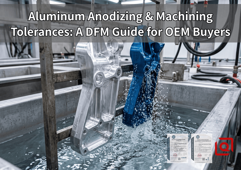
When high-precision CNC parts leave the milling center, they might sit within a strict ±0.005 mm window. Two days later, after chemical dipping and electrochemical growth, the inspection pin fails to enter the locating bore. The internal threads seize. The mating shaft refuses to slide into its bearing seat.
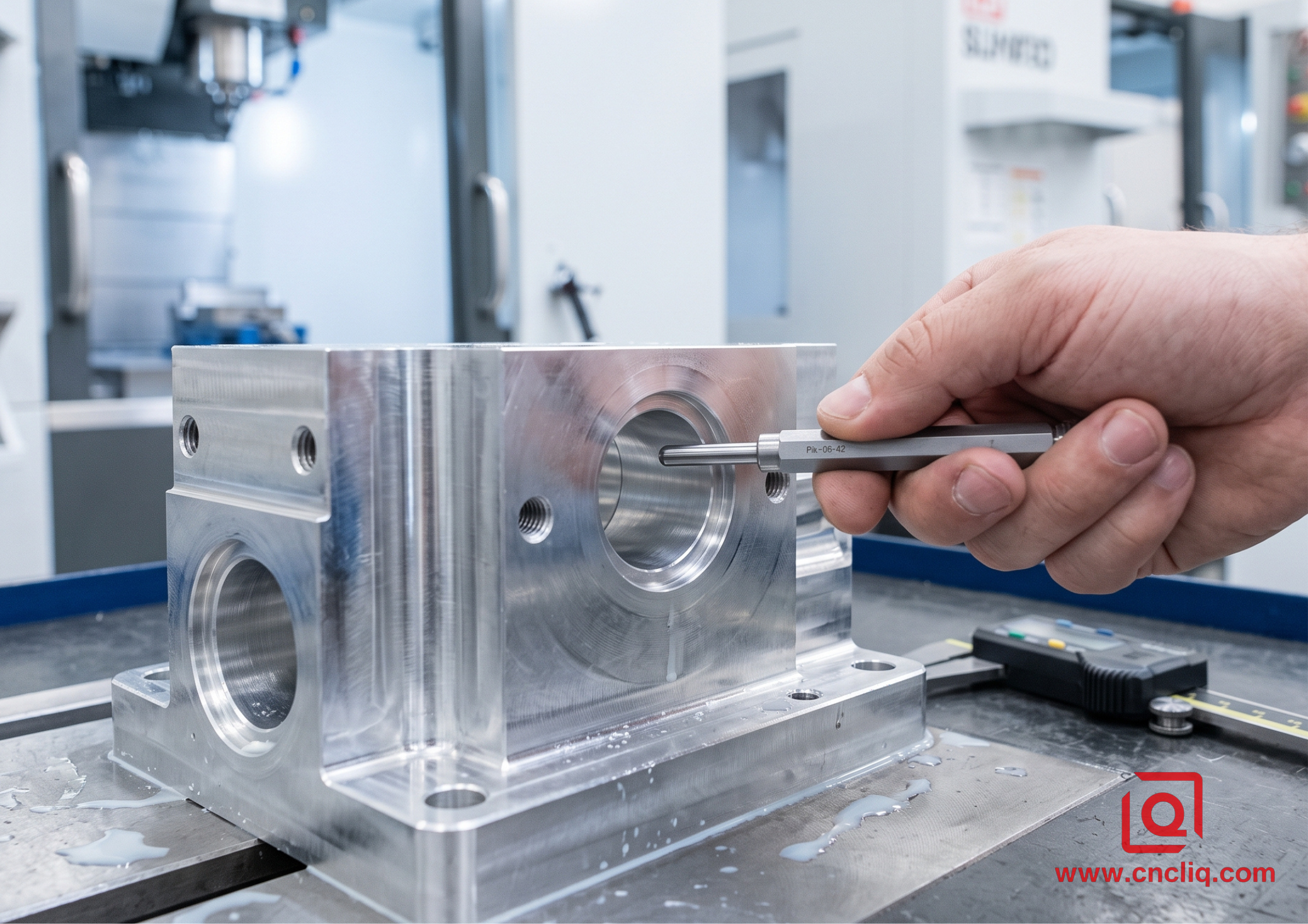
This happens constantly across precision OEM manufacturing programs.
Most machine shops mill aluminum accurately. Problems start when teams treat finishing as simple cosmetic wrap-up instead of a step that changes part geometry. Anodizing isn’t paint—it doesn't just coat the surface. The bath actually eats into raw aluminum as the oxide shell grows outward.
Let’s look at how anodizing throws off tight tolerances in the real world, and what you must bake into your prints before machining starts.
The 50/50 Rule: Penetration vs. Build-Up
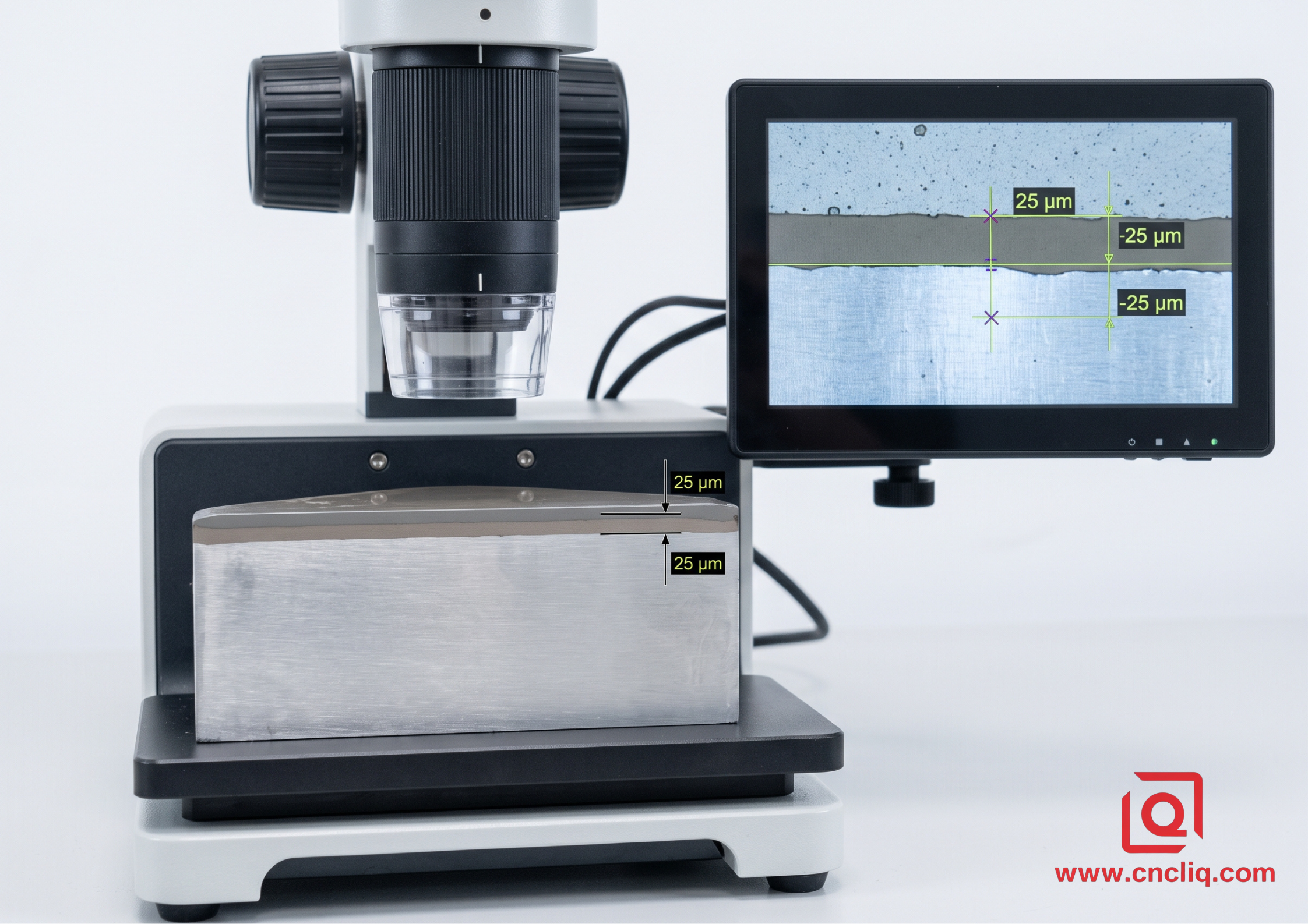
Anodic coatings grow both into and out of the aluminum substrate. Understanding the physical split between penetration and build-up is the baseline of any tolerance calculation.
       Original Metal Surface Line
------------------------------------------
▲  +50% Build-Up (Adds to Part Dimension)
------------------------------------------
▼  -50% Penetration (Consumes Base Metal)
For conventional Type II sulfuric acid anodizing and Type III hardcoat, the standard volumetric growth follows a rough 50% penetration / 50% build-up ratio:
-
50% of the total oxide layer thickness consumes the base aluminum alloy (penetrating inward).
-
50% of the total oxide layer thickness expands outward from the original surface boundary (building outward).
Geometric Dimensional Shifts
Because build-up occurs on every exposed surface, total feature changes depend on part geometry:
-
Shaft Diameters (OD): Swell by 1x full film callout (0.5x outward growth per side × 2 faces).
-
Hole Features (ID): Close down by 1x full film callout (0.5x inward growth per wall × 2 walls).
- Flat Surfaces: Gain 0.5x nominal film build.
Call out 50 µm (0.0020") Type III hardcoat on a 25.000 mm dowel, and you’ll gauge around 25.050 mm out of the tank. If the lathe hand turned it dead-on to 25.000 mm ±0.005 mm pre-plate, that pin is never sliding into its H7 bore.
Manufacturing Standards: Type II vs. Type III Reference
Under MIL-A-8625F and ISO 7599 / ISO 10074, coatings fall into distinct functional classes that dictate exact tolerance allowances.
| Specification | Process Type | Typical Coating Thickness Range | Dimensional Growth per Surface | Typical Applications |
| MIL-A-8625 Type II, Class 1 & 2 | Sulfuric Acid Anodize (Standard / Decorative) | 8 µm to 20 µm (0.0003" to 0.0008") | +4 µm to +10 µm | Enclosures, brackets, cosmetic panels, dyed consumer housings |
| MIL-A-8625 Type III, Class 1 & 2 | Hardcoat Anodize (Engineering / Hard) | 25 µm to 75 µm (0.0010" to 0.0030") | +12.5 µm to +37.5 µm | Hydraulic pistons, slide rails, aerospace actuators, wear rings |
| MIL-DTL-5541 Type II | Chemical Conversion Coating (Alodine / Chem Film) | 0.2 µm to 1.0 µm (<0.00004") | Negligible (~0.0 µm) | Grounding surfaces, EMI enclosures, paint pre-treatment |
Note: While MIL-DTL-5541 chemical film produces virtually zero dimensional change, it provides minimal mechanical wear resistance compared to Type II or Type III electrolytic coatings.
Alloy Microstructure & Bath Chemistry: Why Growth Varies
Calculations on paper assume pure, predictable conversion rates. In the tank, alloy composition alters bath reaction rates.
High-Purity vs. High-Silicon & Copper Alloys
- 6000-Series (e.g., 6061-T6, 6082-T6): Your safest bet for holding tight prints. A clean balance of magnesium and silicon (0.8%–1.2% Mg, 0.4%–0.8% Si) forms dense, rock-solid oxide columns. Growth numbers track within ±10% of standard cut sheets.
- 7000-Series (e.g., 7075-T651): High zinc (5.1%–6.1% Zn) paired with copper (1.2%–2.0% Cu) disrupts the barrier film during the dip. The resulting film drops in hardness, forcing tank temps down near 0°C to 4°C for proper hard anodizing. Build-up shifts too—typically splitting around 40% outward growth to 60% inward penetration.
-
2000-Series (e.g., 2024-T351): High copper (3.8%–4.9% Cu) requires specialized low-voltage tank setups to avoid burning. Coating thickness builds slowly, requiring tighter current density controls.
-
Die-Cast Alloys (e.g., A380, ADC12): Silicon content exceeds 9%. Silicon particles remain undissolved in the bath, creating irregular oxide pathways and dark, blotchy cosmetic finishes. Thickness uniformity degrades rapidly across complex draft angles.
Critical Features: Threads, Press-Fits, and Bores
Certain geometric features react aggressively to chemical baths. These areas require distinct machining compensations.
       TAPPED THREAD CLEARANCE SHIFT (60° PROFILE)

              /\
             /  \  ◄--- Build-up occurs on BOTH flanks
            /    \
           /      \
          /________\

  Pitch Diameter Closes by: ~4x Surface Build-up (2x Coating Thickness)
1. Internal Threads (Tapped Holes)
On a standard 60° metric or UNC/UNF thread profile, plating build-up on the 30° flank angles multiplies pitch diameter shifts.
-
The Math: The pitch diameter shrinks by roughly 4 times the per-surface build-up (or 2 times the total coating thickness).
-
The Impact: A 30 µm Type III coating reduces an internal thread pitch diameter by approximately 60 µm (0.060 mm). Standard Class 6H taps will yield undersized threads that seize bolts.
-
The Solution: Use oversize taps (e.g., 6G or custom +0.05 mm / +0.10 mm pre-plate taps) before sending parts to the anodizing line. Alternatively, plug smaller blind threads below M4 using silicone stoppers.
2. Precision Bearing Bores and Dowel Holes
For dowel pin press-fits (e.g., H7 tolerance, spanning a tight +0.012 mm window), an uncontrolled 15 µm build-up will turn a light press-fit into an impossible assembly.
-
Machining Rule: Open the bore by the expected diameter reduction during boring or reaming operations.
-
Alternative Route: Machine to final nominal size, apply custom tapered silicone plugs during anodizing, and perform a light post-anodize reaming or burnishing pass if bare conductive contact or zero-step shoulders are required.
3. Edge Break Radii
Anodizing always bites you at dead-sharp 90° corners. High current density spikes right at raw tips, leaving you with burnt features, brittle burrs, or bare patches.
- Shop Rule: Break every outside edge with at least a 0.5 mm radius (R0.5) or a 0.3 mm × 45° chamfer prior to plating. That stabilizes tank voltage resistance across the profile and stops the oxide from chipping off during final assembly.
Real-World Case: The High-Speed Optical Housing
A customer in the automated inspection sector submitted a 6061-T6 aluminum optical sensor housing. The mechanical package required high surface hardness for cyclic slide wear, alongside tight positioning accuracy for optical sensor barrels.
+-------------------------------------------------------------------------+
| CASE STUDY: OPTICAL SENSOR HOUSING (6061-T6)                           |
+-------------------------------------------------------------------------+
| Target Specs:                                                           |
|  - Bearing Bore: Ø32.000 mm (+0.009 / -0.000 mm, ISO H6)                |
|  - Finish: MIL-A-8625 Type III, Class 2 (Black Hardcoat, 40 µm target)  |
|  - Mounting Threads: 8x M3x0.5 blind tapped holes                       |
+-------------------------------------------------------------------------+
| Pre-Optimization Risk:                                                  |
|  - 40 µm hardcoat = 20 µm build-up/surface -> Ø32 bore shrinks 40 µm    |
|  - M3x0.5 internal pitch diameter shrinks ~40 µm -> Fastener lockup     |
+-------------------------------------------------------------------------+
| Implemented DFM Adjustments:                                            |
|  1. Bore Pre-Machined Size: Ø32.040 mm (+0.008 / -0.000 mm)             |
|  2. Tapping Tooling: Switched from standard 6H to oversized 6G taps     |
|  3. Racking Strategy: Machined M4 auxiliary threaded holes on back      |
+-------------------------------------------------------------------------+
| Final CMM Inspection Results:                                           |
|  - Final Post-Coat Bore ID: Ø32.004 mm (Within H6 limits)               |
|  - Thread Fit: 100% pass rate with standard GO / NO-GO plug gauges      |
|  - Scrap Rate: Reduced from 18.5% on prototype runs to 0% in production |
+-------------------------------------------------------------------------+
The Inspection Data
On the prototype run, the housing was machined directly to nominal print dimensions (Ø32.002 mm). After a standard 40 µm hardcoat cycle, the bore closed to Ø31.962 mm. The assembly technician attempted to press the stainless steel bearing, causing local shear tearing of the anodic layer and binding the rotary stage.
For the revised run, we dialed in fresh offsets in the CAM file. The mill roughed and finish-bored the ID out to Ø32.042 mm.
Once pulled from the tank after dialing in a 40 µm coat (splitting 20 µm penetration into the metal and 20 µm growth per side), the CMM logged an average bore of Ø32.003 mm. The bearings pressed right in at standard tonnage (1.2 kN) without flaking a bit of oxide.
Masking vs. Pre-Sizing: Choosing the Cost-Effective Path
OEM buyers often ask: "Should we mask tight-tolerance features or pre-machine them to compensate for growth?"
                    FEATURE TOLERANCE DECISION MATRIX

                              Is Tolerance
                             Tighter than
                              ±0.008 mm?
                               /       \
                             YES        NO
                             /           \
               Is feature conductive?    Compensate via CNC Offsets
                     /         \          (Pre-machining saves cost)
                   YES          NO
                   /             \
        Custom Silicone Plugs    Liquid Masking Lacquer
        (Reusable, Fast)         (Labor-intensive, High scrap risk)
-
Cut the Allowance Upfront (Cheapest Path): Once batch quantities top 100 pieces and you’re holding ±0.010 mm to ±0.025 mm, programming offsets straight in CAM is your quickest, no-mess fix. It eliminates manual labor on the finishing line.
-
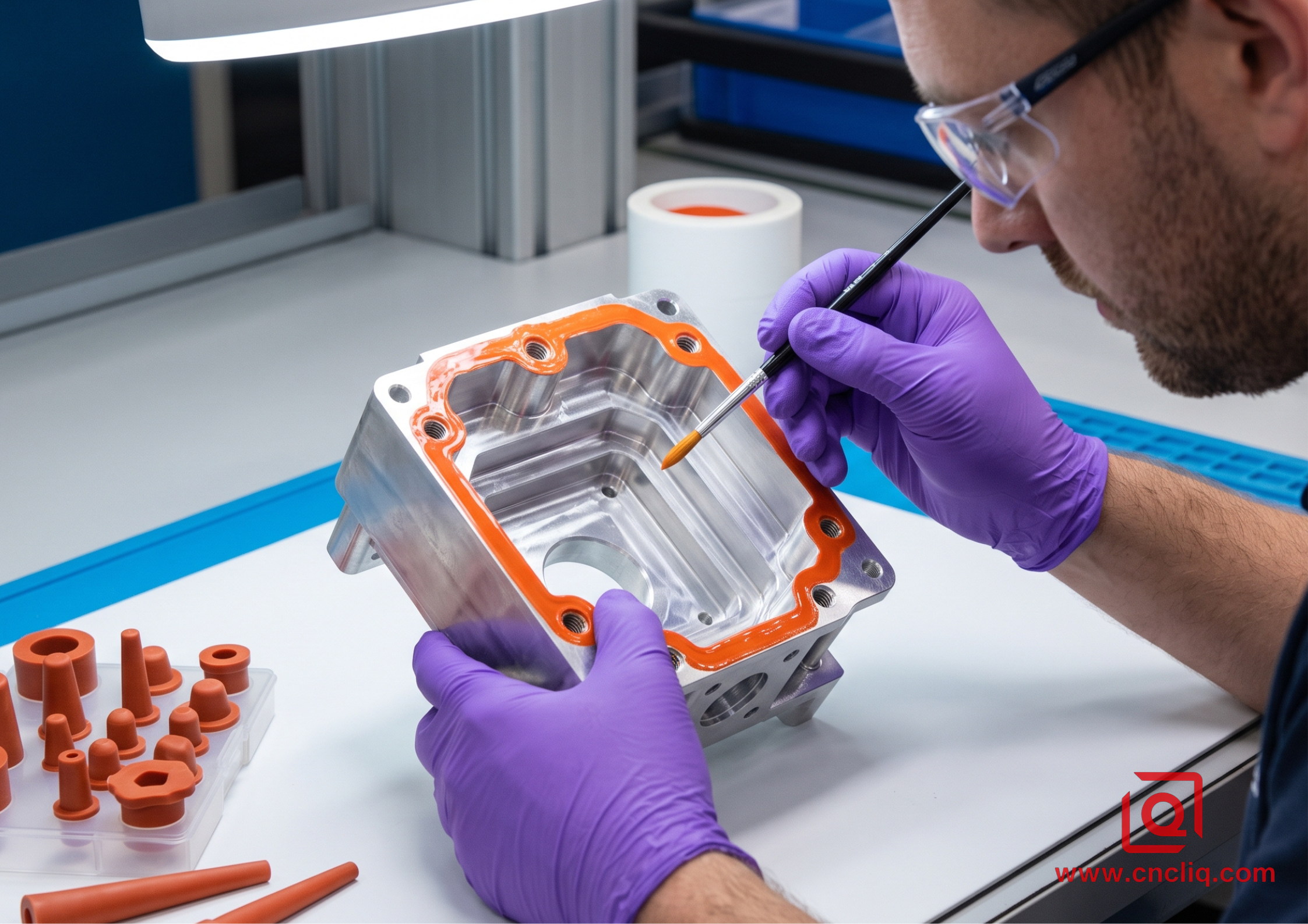
Standard Silicone Masking Plugs: Ideal for through-holes, threaded holes, and standard shaft ends where the surface does not need wear protection. Standard tapered plugs cost pennies and install quickly.
-
Complex Custom Liquid Masking: Applying liquid stop-off lacquer to irregular steps, flat sealing surfaces, or tight deep-pocket geometries requires manual brush application and careful curing. This adds significant touch time and unit cost. Avoid this unless electrical grounding requires bare aluminum surfaces adjacent to hard-anodized slides.
Actionable Drawing Checklist for OEM Buyers
To keep from tossing entire lots in the scrap bin or drowning in rework orders, bake these checks straight into your CAD models and prints:
- Spell Out Plating Specs: Drop lazy drawing notes like "Hardcoat per MIL-A-8625". Put down the real numbers: "MIL-A-8625, Type III, Class 1, 40 µm ±5 µm thickness".
- Lock Down Where Numbers Count: Flag up front if tight limits hold BEFORE or AFTER dip. Slap on the note: "All critical dimensions apply after final surface treatment."
-
Call Out Masking on the Print: Highlight non-anodized faces with distinct hatching and include the note: "Marked areas to be masked free of anodize. Conductive bare aluminum required."
-
Identify Racking Zones: Anodizing requires electrical contact (typically via titanium or aluminum racks). Tight clamping leaves a small contact mark without coating. Define allowable non-critical surfaces for rack contacts on the drawing (e.g., inside an unthreaded clearance hole or along a non-cosmetic back edge).
Locking in these DFM calls upfront during quoting and first-article runs keeps your CNC chips and the plating line aligned. The payoff? Finished aluminum hardware that hits tight print limits, stays on dollar targets, and ships out on time.
FAQs
Q1: Can we achieve tight bearing tolerances (such as ISO H6 or H7) directly through hardcoat anodizing without post-machining?
Yes, but only under strict process controls. Achieving an H6 (+0.009 / -0.000 mm) or H7 (+0.012 / -0.000 mm) tolerance post-plate requires the machine shop to hold a ±0.003 mm pre-plating machining window, paired with an anodizing line running automated current-density rectifiers capable of holding coating growth to within ±3 µm. If your batch size is small or your plating partner runs manual tank dips with ±10 µm thickness swings, pre-machining to size and applying custom tapered silicone plugs during anodizing is the far safer, more repeatable route.
Q2: What happens to your raw stock sizes during caustic wash before any voltage hits the tank?
A standard lye dip (sodium hydroxide) cleans off fuzz burrs and levels out a flat matte look. Catch is, it eats raw aluminum—normally taking off 2 µm to 10 µm (0.0001" to 0.0004") per face based on bath heat and dwell time. Holding fine limits? Call out a "mild non-etch wash" or a "fluoride acid etch" right on the print. Heavy caustic etching on precision bores can wash out pre-machined compensation margins before the electrolytic build-up even starts.
Q3: Why do internal blind tapped holes under M4 frequently fail thread gauges after anodizing?
Blind holes under M4 suffer from solution entrapment and localized over-concentration of current. Tank fluids struggle to circulate inside narrow blind cavities, resulting in uneven anodic growth and trapped acidic baths that corrode thread roots during the hot water sealing phase. Trapped air pockets in deep blind cavities will starve the walls of current and fluid, leaving raw bare spots. If you’re dealing with threaded features under M4, push silicone caps into the lead threads or run a pre-plate tap pitched +0.05 mm heavy upfront.
Q4: If an anodized part runs fat on the gage, can we strip the film and re-dip it?
Technically yes, but stripping murders your finished tolerances. A hot chromic-phosphoric tank wipes out the oxide layer entirely. Since original growth already ate 50% of its depth straight out of the core stock, stripping leaves the raw metal undersized by that exact bite (e.g., stripping a 40 µm hardcoat drops ODs by roughly 40 µm total). Stripping and re-coating precision features will inevitably destroy close tolerances unless the feature is subsequently machined to an oversized repair dimension.
Q5: What is the difference in dimensional impact between Clear (Natural) Anodizing and Black Anodizing?
The dye stage itself adds essentially zero measurable thickness. Organic black dyes absorb into the unsealed microscopic pores of the oxide layer before the final sealing tank closes them. However, colored/black parts often receive a slightly longer anodizing run time to build deeper pores for adequate dye absorption (typically 15 µm to 25 µm total thickness) compared to standard clear protective finishes (which may only run 8 µm to 12 µm). It is this difference in target baseline coating thickness—not the dye itself—that causes greater dimensional growth on dyed components.
Summary
Aluminum anodizing follows a 50% penetration / 50% build-up rule, increasing outer dimensions and shrinking inner bores by 1x total coating thickness while reducing internal 60° thread pitch diameters by 2x total thickness. To prevent assembly failure, engineers must offset dimensions prior to finishing based on specification targets—typically 8 µm to 20 µm for standard Type II cosmetic anodizing and 25 µm to 75 µm for wear-resistant Type III hardcoat—or protect ultra-tight features (such as ISO H6/H7 bores and sub-M4 threads) using silicone masking plugs to bypass the destructive dimensional losses of stripping.
Contact Information
Disclaimer
All technical articles, material specifications, machining recommendations, and surface treatment details published on this blog are for informational and reference purposes only. Please note that general blog insights do not replace signed technical agreements. Because custom parts vary by material heat numbers, machine calibrations, and specific tolerances, binding quality specs are governed solely by your approved CAD drawings, signed contracts, and formal quality plans.
All customer case studies featured on this blog have been thoroughly anonymized and sanitized. The performance metrics, manufacturing workflows, and imagery displayed serve solely to demonstrate our custom machining capabilities and do not represent a single universal standard for all orders.
Liqin Manufacturing Team
Built on 18 years of precision engineering experience, Ningbo Liqin Industry manufactures high-tolerance metal components for demanding global markets. We operate out of a 6,500 m² production hub equipped with over 150 machines, running 4-axis and 5-axis CNC machining, mill-turn machining, cold extrusion, and pressure die casting under one roof. This setup allows us to manage projects seamlessly, taking parts from initial CAD concepts directly to finalized shipments.
We handle quality control with zero compromise. We treat tight tolerances with the engineering discipline they require. Backed by ISO 9001, ISO 13485, and IATF 16949 certifications, our QA engineers run strict IPQC, FQC, and OQC checks on every single production batch. From CMM dimensional mapping and optical profiling to hardness and salt-spray testing, we validate your critical specs upfront—so you receive drop-in ready components with zero assembly headaches or costly line stoppages. On top of manufacturing, you can rely on us for two-hour response times on new RFQs, direct support for prototype sampling, and smooth export shipping across Europe, North America, Asia, and Oceania.
Welcome your inquiries and samples. Visit our website or contact us directly for a competitive quote!
