 English




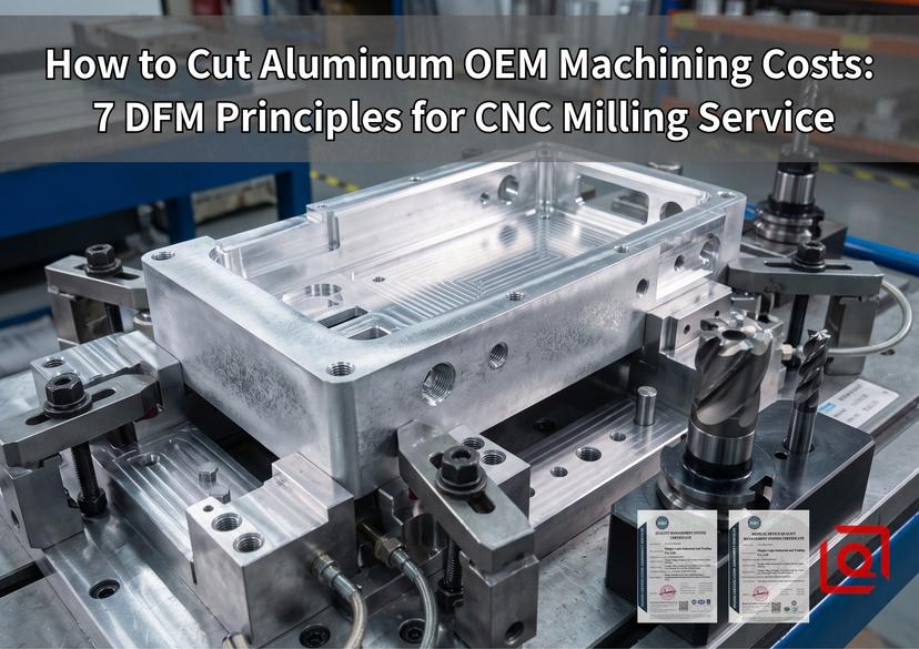
Every extra minute that stock sits under a spindle eats into your margins. When we quote custom 6061-T6 or 7075-T651 milling jobs, we aren’t just weighing aluminum billets—we’re tallying tool engagement hours, extra fixture setups, non-standard tooling needs, and the odds of scrapping a part.
Bloated CNC quotes rarely come down to raw stock prices. Instead, they trace right back to features on your prints that force 3-axis and 5-axis machines into sluggish feed rates, constant part flipping, or chewed-up cutters.
Dialing in practical DFM habits early in CAD drafting chops out roughly 45% of overall machining overhead—without giving up structural stiffness or true-position tolerances.
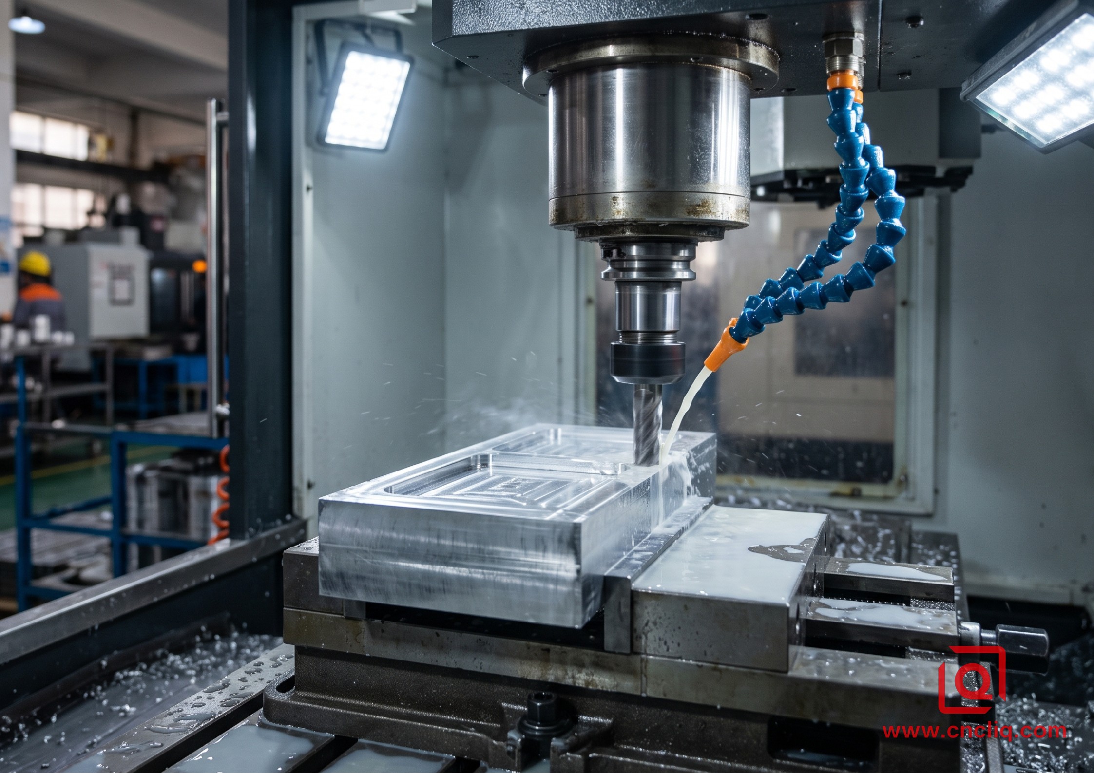
1. Match Internal Corner Radii to Standard Tool Aspect Ratios
Square internal vertical corners cannot be milled with rotary tooling. When a drawing specifies a sharp internal corner, the machinist must switch from high-speed milling to wire electrical discharge machining (WEDM) or broaching—instantly doubling cycle time and fixture handling.
Even standard corner fillets bite your wallet if the CAD model matches off-the-shelf end mill radii 1:1. Run a 6 mm tool directly into a 6 mm inside pocket corner, and tool engagement angle jumps from 90° straight to 180°. Radial cutting forces spike on the spot, causing nasty spindle chatter, wavy side walls, and visible tool deflection. The machine operator is forced to drop feed rates by 60% or program trochoidal milling cycles with multiple stepovers.
Corner Design Rule: Radius ≥ 1.15 × Tool Radius
Pocket Depth-to-Corner Ratio: Keep Cavity Depth ≤ 3 × Tool Diameter (D)
-
The Fix: Always specify internal corner radii at least 15% larger than standard end mill dimensions. If a deep pocket needs a 10 mm end mill (5 mm nose radius), sketch that internal fillet at 5.75 mm to 6.0 mm instead. This extra clearance lets our CAM toolpath sweep right through the turn without slamming the brakes, shaving 30% off your corner cycle times.
2. Standardize Pocket Cavity Depths and Floor Transitions
Deep pockets with high aspect ratios demand long-reach cutting tools. Push a solid carbide end mill past a 3:1 length-to-diameter (L/D) stickout, and cutting forces start bending the tool along a punishing cubic curve (Deflection ∝ L³ ).
Tool Overhang Impact:
L/D = 3:1  --> Baseline stability, full feed rates (e.g., fz = 0.08 mm/tooth)
L/D = 5:1  --> Deflection increases by ~4.6x; feed must drop 40%
L/D = 8:1  --> Extreme harmonics, severe chatter, 70% feed reduction required
Try hogging out a 60 mm deep pocket using an 8 mm end mill (L/D = 7.5), and you will hear that cutter scream against the sidewalls immediately. To keep the shank from snapping, we have to throttle our depth-of-cut (ap) down to 0.5 mm per pass and crank through-spindle coolant up to 70 bar just to blast chips clear. Right there, a crisp 4-minute roughing cycle morphs into a 22-minute shop bottleneck.
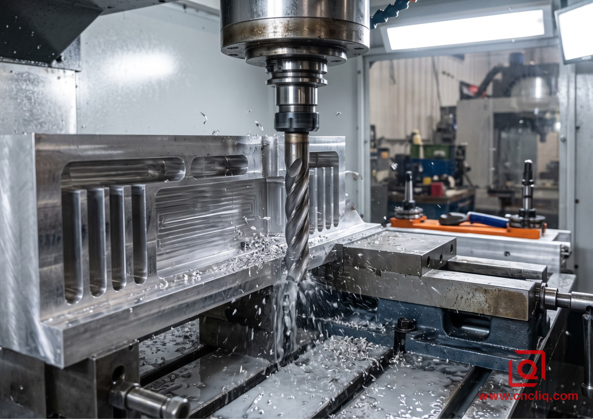
- Floor-to-Wall Radii: Dead-sharp floor corners force us to drag flat bottom end mills across the entire base to scrape out corners. Give us a modest bottom radius instead (0.5 mm to 1.5 mm). That simple tweak lets us drop in bull-nose tools with rugged corner radii, which soak up heavy chip loads and stop tip chipping cold.
3. Maintain Stable Wall Thickness to Suppress Resonance
Thin aluminum walls lack rigidity. Push sideways against free-standing walls below 1.0 mm, and that thin stock flexes right away from your end mill, leaving you with an out-of-spec taper down the Z-axis. Worse still, those flimsy ribs love to sing at harmonic resonance once you spin the spindle up to 12,000 to 18,000 RPM, chewing up the finish with ugly chatter marks that will get your batch rejected at QA inspection.
| Aluminum Alloy | Minimum Recommended Wall (Free-standing) | Supported Wall (Pocket Rib) | Height-to-Thickness Limit |
| AL6061-T6 | 1.20 mm | 0.80 mm | Max 8:1 |
| AL7075-T651 | 1.00 mm | 0.65 mm | Max 10:1 |
| AL5052-H32 | 1.50 mm | 1.00 mm | Max 6:1 |
To machine a 0.6 mm wall without chatter, the machinist must run micro-step depths (ap = 0.2mm), step down in opposing passes on both sides, or support the wall with specialized vibration-dampening fixtures. Designing walls with a continuous base taper or keeping thickness ≥ 1.2mm allows the operator to push radial feed rates without chatter.
4. Optimize Thread Depths and Standardize Hole Geometry
Tapping blind holes in aerospace-grade 6061-T6 and 7075 aluminum creates major failure points when drawings demand full thread engagement down to the absolute bottom of a hole.
Real-world pull tests prove the first 3 to 5 threads take over 75% of the entire tensile load. Tapping deeper than 2× the nominal bolt diameter (2D) buys you zero usable strength—it just invites broken tooling.
- Drill Depth Clearance: Spiral flute taps push a nest of chips straight to the hole floor. Call out an M6x1.0 thread at 12 mm depth inside a 13 mm pre-drilled blind hole, and that tap will bottom out on packed swarf, seize, and snap flush. Digging out a shattered carbide tap means hauling the part over to sinker EDM burning, grinding your spindle line to a dead stop.
- Lock to Standard Hole Sizes: Tie every blind and thru hole to off-the-shelf jobber drill sizes (like 3.3 mm for M4, 4.2 mm for M5, 5.0 mm for M6, 6.8 mm for M8). Oddball hole calls force us to ditch rapid pecking cycles and helical-interpolate the bores with tiny end mills, easily tripling run times across multi-hole bolt patterns.
5. Consolidate Geometric Tolerances (GD&T) and Surface Roughness (Ra)
Slapping tight limits across non-critical cosmetic faces just burns your budget for nothing. Drop a ±0.010 mm linear tolerance or call out sub-0.025 mm true position everywhere on the drawing, and you force us to take slow spring passes, dial in pricey finishing cutters, and park every finished part under a CMM (Coordinate Measuring Machine) probe for 100% inspection.
Manufacturing Cost by Surface Roughness:
Ra 3.2 µm (Standard Milled Surface)   --> 1.0x Baseline Cost (High-feed rough/finish)
Ra 1.6 µm (Fine Machined Surface)       --> 1.4x Cost (Lower stepover, dedicated finish pass)
Ra 0.8 µm (Precision Bearing Interface) --> 2.1x Cost (High-RPM, fine feeds, tool wear monitoring)
Ra 0.4 µm (Super-finish / Polished)     --> 3.5x+ Cost (Secondary grinding or manual lapping)
Apply general tolerances based on ISO 2768-m (Medium) for non-critical features, reserving ISO 2768-f (Fine) or ASME Y14.5 precision controls strictly for dowel locations, bearing journals, and dynamic sealing grooves.
6. Cut Fixture Flips with Smart Workholding
Every time an operator unclamps a vise, clears out swarf, drops your part into another fixture, and re-zeros coordinate work offsets, your bill climbs and datum shift stacks up. If a drawing makes our 3-axis mills touch all 6 sides across multiple setups, we have to mill bespoke soft jaws and spin alignment pins just to get through Op10, Op20, Op30, and Op40.
- Keep Features Accessible from Above: Pack as many bosses, pockets, slots, and threads into a single top-down Z-axis approach as you practically can.
- Ditch Side Undercuts: Avoid buried side channels or recessed pockets that make us hunt down custom lollipop mills, run specialty woodruff cutters, or tie up a 5-axis spindle line.
- Model Sacrificial Clamping Lugs: If a tricky geometry calls for milling 5 faces on a 5-axis table, leave 3.0 mm of extra stock at the bottom. We can bite onto that prep stock with a dovetail vise and sweep all 5 sides in one clean program.
7. Match Alloy Selection to Secondary Anodizing Specifications
Spec'ing 7075-T651 instead of plain-old 6061-T6 instantly bumps raw stock bills by a solid 40% to 60%. Sure, 7075 packs serious muscle with superior yield strength (503 MPa vs. 276 MPa), but that extra zinc bites back: it chews through carbide inserts faster and leaves parts far more prone to pitting during standard clear anodizing.
| Parameter | AL6061-T6 | AL7075-T651 | AL5052-H32 |
| Machinability Index | 100% (Baseline) | 85% (High Tool Wear) | 75% (Gummy Chip Formation) |
| Raw Material Cost | Baseline | +45% to +60% | -5% to -10% |
| Hard Anodizing Quality | Excellent (MIL-A-8625 Type III) | Moderate (Higher Si/Zn inclusions) | Good (Sheet metal & casings) |
| Typical Cutting Speed ($v_c$) | 300 - 650 m/min | 250 - 500 m/min | 200 - 400 m/min |
- Factor in Plating Growth: If you call out Type II sulfuric anodizing (10-15 μm layer) or Type III hard anodizing (25-50 μm layer), remember that dimensions grow on tight bearing bores and threads. Hardcoat builds 50% into the base aluminum and 50% out into open space.
- A 25 μm layer stacks 25 μm on each face, choking an inside hole diameter by 50 μm overall. Mark clearly on your 2D print whether your tight limits apply pre-plate or post-plate. Otherwise, you risk tossing an entire finished batch straight into the scrap bin right after the chemical tanks.
Engineering Case Study: DFM Optimization on Optical Sensor Enclosure
An overseas client in the industrial sensing sector provided a CAD model for a batch of 2,500 OEM optical sensor chassis. The initial design suffered from high cycle times and frequent tool wear.
Initial Design Constraints:
- Internal Corner Radii: R1.5 mm on deep pockets (Pocket depth = 28 mm, Aspect Ratio = 9.3:1)
- Thread Specification: M3x0.5 threaded down to 10 mm depth in blind holes (3.3D)
- Wall Thickness: 0.70 mm outer shielding ribs
- Side Features: Cross-drilled wiring ports across 4 separate faces
- Tolerance Callout: General profile tolerance of ±0.015 mm applied across all outer surfaces
Engineering DFM Re-Design:
1. Increased internal pocket corner radii from R1.5 mm to R3.5 mm; standardized cavity depth to 24 mm.
2. Shortened M3 thread engagement length from 10 mm to 6 mm (2D), leaving a 3 mm unthreaded drill relief.
3. Thickened external ribs from 0.70 mm to 1.35 mm.
4. Re-routed side wiring ports to the rear face, consolidating features onto 2 accessible setups.
5. Re-assigned general tolerances to ISO 2768-m; isolated ±0.010 mm tolerances strictly to sensor mounting pads.
Production Results (Batch size: 2,500 pcs):
- Cycle Time per Unit: Dropped from 44.5 minutes to 16.2 minutes (63.6% reduction)
- Tool Life per Insert Set: Increased from 45 parts to 260 parts
- Scrap / Rejection Rate: Dropped from 4.8% to 0.15%
- Net Unit Cost Reduction: 38.4%

Key DFM Execution Checklist for Sourcing Engineers
Before submitting your 3D CAD files (STEP/IGES) and 2D engineering drawings (PDF/DWG) for formal production quoting, verify these shop-floor rules:
-
[ ] All internal vertical corner radii measure ≥1.15× standard mill radius (R ≥ Cavity Depth / 3).
-
[ ] Pocket cavity depth does not exceed 4× standard tool diameter.
-
[ ] Free-standing structural walls maintain a minimum thickness of 1.2 mm (6061-T6).
-
[ ] Thread engagement depths are capped between 1.5D and 2.0D with clear drill depth relief.
-
[ ] Surface roughness callouts of Ra ≤ 0.8μm are restricted to functional sealing and bearing seats.
-
[ ] All non-critical linear and angular dimensions default to ISO 2768-m.
-
[ ] Part features are accessible within a maximum of 2 workholding setups.
-
[ ] Thread and bore dimensions clearly state pre-plate or post-plate tolerance requirements for MIL-A-8625 anodizing.
FAQs
Q1: Where should I set inside corner radii on milled aluminum pockets?
A: Rule of thumb from our shop floor: shoot for corner radii at 1/3 of total pocket depth, or at least 1.15× your planned tool radius. Cutting an 8.0 mm deep slot? Spec those floor corners at R3.0 mm or wider. That tiny bit of breathing room lets a standard 5.0 mm or 6.0 mm end mill glide right around the bend without biting, cutting out spindle chatter and dodging painful sinker EDM burning entirely.
Q2: What is the safest wall thickness floor for custom 6061-T6 parts?
A: Target at least 1.2 mm on tall unsupported outer walls, and hold 0.8 mm on tied-in internal ribs. Skim below 0.8 mm, and that thin stock will deflect under raw vise clamping pressure or rattle once your spindle winds up, leaving you with an out-of-square taper and rough chatter marks across the face.
Q3: How deep should threaded blind holes be modeled in custom aluminum parts?
A: Keep effective thread engagement between 1.5D and 2.0D (e.g., 6.0 mm to 8.0 mm depth for an M4 screw). Always extend the unthreaded drill bottom by at least 3 times the thread pitch past the thread runout to prevent tap binding and breakage from packed chips.
Q4: How does switching to ISO 2768-m general tolerances lower unit machining quotes?
A: Applying ISO 2768-m (±0.1 mm to ±0.2 mm) to non-critical profiles eliminates up to 60% feed-rate penalties and removes intermediate CMM inspection stops. Restricting ±0.005 mm to fewer than 3 functional datums reduces part cycle time by 20% to 35%.
Q5: What dimensional growth should we plan for under MIL-A-8625 anodizing?
A: Expect a 10 to 15 µm coat with standard Type II sulfuric anodizing—half bites 50% into the core stock, while the other 50% pushes outward, fattening your overall outer width by that exact 10 to 15 µm. Step up to Type III hardcoat, and you get a rugged 25 to 50 µm armor that closes in on your precision bores, pinching internal diameters down by a hefty 25 to 50 µm. Save us the headache: flag pre-plate dimensions right on the 2D print, or tag tight bearing bores for rubber plugs and masking.
Summary
Slashing piece costs on custom aluminum parts was never about cutting quality corners. It is simply about matching your CAD model with how end mills actually bite into metal on a real CNC machine bed.
When you open up corner radii, set tiered tolerances, ditch buried pockets, and cut down fixture flips, our spindles run uninterrupted. You eliminate machining bottlenecks, protect cutter flutes, and spare our operators endless headaches. Taking 10 minutes to dial in clean DFM tweaks on your screen keeps the shop floor humming, letting us ship dead-accurate OEM parts at the leanest possible unit price.
Contact Information
Disclaimer
All technical articles, material specifications, machining recommendations, and surface treatment details published on this blog are for informational and reference purposes only. Please note that general blog insights do not replace signed technical agreements. Because custom parts vary by material heat numbers, machine calibrations, and specific tolerances, binding quality specs are governed solely by your approved CAD drawings, signed contracts, and formal quality plans.
All customer case studies featured on this blog have been thoroughly anonymized and sanitized. The performance metrics, manufacturing workflows, and imagery displayed serve solely to demonstrate our custom machining capabilities and do not represent a single universal standard for all orders.
Liqin Manufacturing Team
Built on 18 years of precision engineering experience, Ningbo Liqin Industry manufactures high-tolerance metal components for demanding global markets. We operate out of a 6,500 m² production hub equipped with over 150 machines, running 4-axis and 5-axis CNC machining, mill-turn machining, cold extrusion, and pressure die casting under one roof. This setup allows us to manage projects seamlessly, taking parts from initial CAD concepts directly to finalized shipments.
We handle quality control with zero compromise. We treat tight tolerances with the engineering discipline they require. Backed by ISO 9001, ISO 13485, and IATF 16949 certifications, our QA engineers run strict IPQC, FQC, and OQC checks on every single production batch. From CMM dimensional mapping and optical profiling to hardness and salt-spray testing, we validate your critical specs upfront—so you receive drop-in ready components with zero assembly headaches or costly line stoppages. On top of manufacturing, you can rely on us for two-hour response times on new RFQs, direct support for prototype sampling, and smooth export shipping across Europe, North America, Asia, and Oceania.
Welcome your inquiries and samples. Visit our website or contact us directly for a competitive quote!
