 English




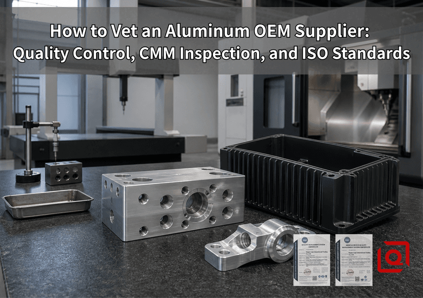
Buying custom aluminum components offshore isn't just a matter of matching line items across RFQ spreadsheets or looking for an ISO 9001 badge on a lobby wall. Let's be honest: anyone can mount a brass plaque. The real test comes when that first skid of 6061-T6 manifold blocks hits your inspection bay—only for you to catch a creeping wall taper, or realize Type III hard anodizing just stole 18 microns (0.018 mm) out of a critical bearing bore.
When evaluating an aluminum OEM partner, look past the sales deck. Walk directly into the quality control lab, observe how machinists address tool deflection on thin ribs, and check how they regulate temperature during metrology.
Here is how shop-floor practice, metrology audits, and supplier qualifications separate precision OEMs from basic parts brokers.
1. Traceability Starts at the Billet Yard: Material Verification
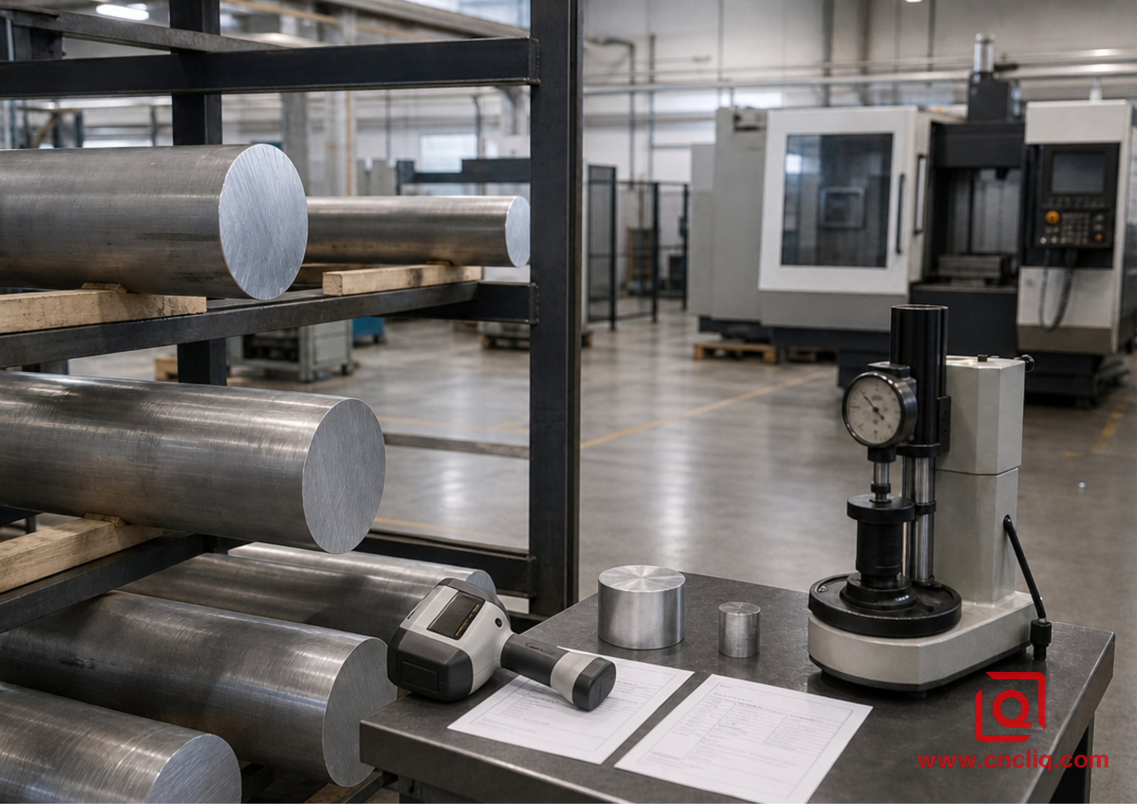
Never accept raw stock certifications on trust. If your raw aluminum runs high on trace zinc or iron, you can kiss clean finishes goodbye—expect ragged burrs right off the spindle and nasty pitting once parts hit the sulfuric bath (MIL-A-8625 Type II).
Two things I always lock down before anyone throws an end mill into the cut:
-
Mill Test Certificates (MTC / EN 10204 3.1): Never skip the paperwork. Demand full chemical trace reports per melt, then walk the rack to match heat lot numbers straight against the hard stampings on each bar or billet.
-
Positive Material Identification (PMI): Don't just trust a PDF. Verify your vendor actively zaps incoming loads with a handheld XRF gun or benchtop OES right at the receiving dock.
-
Hardness Verification: Confirm baseline temper prior to fixture setup. For 6061-T6, hardness must register at least 95 HB (Brinell) or 15 to 17 HW (Webster). Readings below 85 HB indicate incomplete solution heat treatment and artificial aging, causing cutter gumming and part deflection under mechanical clamping forces.
Raw Billet Stock -> PMI / XRF Scan -> Webster Hardness Test -> Batch Traveler Code -> CNC Pallet
2. Metrology Protocols: CMM Inspection & Thermal Stabilization

A high-end bridge Coordinate Measuring Machine (CMM) means very little if it operates in a non-climate-controlled inspection bay beside a 12,000 RPM machining center.
Aluminum features a high coefficient of thermal expansion (CTE):
-
6061-T6 Aluminum CTE: 23.4 x 10⁻⁶ / °C (approx. 23.4 µm/m per °C)
-
Standard Metrology Reference Temp: 20°C (68°F) per ISO 1
A 500 mm structural bracket coming off the mill at 34°C after heavy roughing (feed per tooth fz = 0.18 mm) expands by 0.1638 mm:
500 mm x (23.4 x 10-6 / °C) x (34°C - 20°C) = 0.1638 mm
Probing the part immediately yields a false pass. Once it cools during ocean transit, dimensions contract out of spec.
Vetting Metrology Readiness:
- Thermal Soak Period: Never gauge warm parts off the mill. Let your aluminum soak in a Class 10,000 cleanroom held at 20°C ± 1°C for 4 to 6 hours minimum before anyone pulls a final inspection pass.
- CMM Calibration Records: Ask to see the hard ISO 10360-2 volumetric accuracy logs for their Zeiss, Hexagon, or Mitutoyo rigs. Make sure those field calibration stickers aren't running past due.
- Stylus Rigidity: If you're probing narrow cavities deeper than a 4:1 aspect ratio, watch out for tip deflection. Ensure the programmer threads on stiff carbon fiber or silicon nitride stems, not flimsy stainless rods that flex on touch-trigger hits.
3. Manufacturing, Quality, and Inspection Parameters
Standardize your acceptance thresholds across these inspection benchmarks:
| Parameter / Feature | Manufacturing Standard | Verified Inspection Method | Rejection Threshold |
| Material Chemistry | ASTM B221 / EN 573-3 (6061: Si 0.4%–0.8%, Mg 0.8%–1.2%, Cu 0.15%–0.4%) | Direct OES or Handheld XRF Spectrometer | Chemical composition deviation outside alloy limits; missing raw MTC |
| Hardness (6061-T6) | 95 HB minimum / 15–17 HW | Webster / Brinell Hardness Tester | Hardness < 90 HB (structural failure risk / gumming during milling) |
| Position & True Position | ASME Y14.5-2018 / ISO 1101 (GD&T) | Bridge CMM with continuous scanning probe | True position deviation > 0.025 mm on datum-referenced holes |
| Surface Roughness (Ra) | ISO 4287 (Ra 0.8 µm milled face, Ra 0.4 µm sealing journal) | Contact Stylus Profilometer (Cutoff lambda c = 0.8 mm) | Ra > 1.6 µm on static sealing surfaces; visible tool chatter |
| Anodizing Thickness | MIL-A-8625F Type II (10–25 µm), Type III Hardcoat (40–60 µm) | Eddy-Current Coating Gauge (ISO 2360) | Coating thickness < 10 µm on exterior surfaces; unsealed pores failing dye test |
| Internal Thread Fit | ISO 965-2 / ASME B1.1 (6H or 2B thread class) | Thread Go / No-Go Plug Gauges & Depth Micrometer | No-Go plug enters past 2 full turns; torn pitch threads |
4. First Article Inspection (FAI) & GD&T Competency
A qualified aluminum OEM looks beyond 2D linear dimensions to build functional datum reference frames per ASME Y14.5 or ISO 1101.
Whenever I sign off on an AS9102 or ISO 9001 First Article Inspection (FAI) pack, I look straight past the clean ballooned print and data matrix:
- Datum Setup: Check how their CMM programmer built the primary plane. Did they actually distribute 6 to 8 probe hits across the face, or settle for a lazy 3-point alignment that sweeps real surface waviness (Wt) under the rug?
-
Profile of a Surface: Complex 3D contours require CMM CAD-comparison point clouds, not manual depth micrometer checks.
-
Process Capability (Cpk / Ppk): On critical features like H7 bearing bores, demand capability studies. A qualified OEM delivers Cpk >= 1.33 across a 30-piece pilot run.
5. Post-Processing & Tolerance Pre-Compensation
Machining is only half the battle. Aluminum surface treatments introduce chemical dimensional shifts requiring upstream compensation in CAM toolpaths:
CAM Model (Offset) -> CNC Machining -> Type III Hardcoat (+25 µm/side) -> Final Net Dimension
- Sulfuric Acid Anodizing (Type II): Yields a 10 to 20 µm total film, splitting evenly with 50% penetrating the base metal and 50% building outward.
- Hardcoat Anodizing (Type III): Puts down 40 to 50 µm of hard armor, which chokes internal bores by a full 40 to 50 µm due to the 2 x 20 to 25 µm radial growth.
- Pre-Machining Offsets: Sharp programmers don't guess—they bake these dimensional growth allowances straight into Mastercam or NX toolpaths before cutting metal. They rough and finish critical bearing seats oversize before electrochemical treatment so the final bore settles dead center in the H7 band (+0.015 mm / -0.000 mm).
If the OEM asks: "Should we mask these internal M4x0.7 tapped holes and precision bearing seats, or machine them with pre-plating pitch and diameter offsets?"—hire them immediately. That question proves their engineering team understands precision manufacturing realities.
6. Shop-Floor Case Study: Autonomous Optical Sensor Enclosure
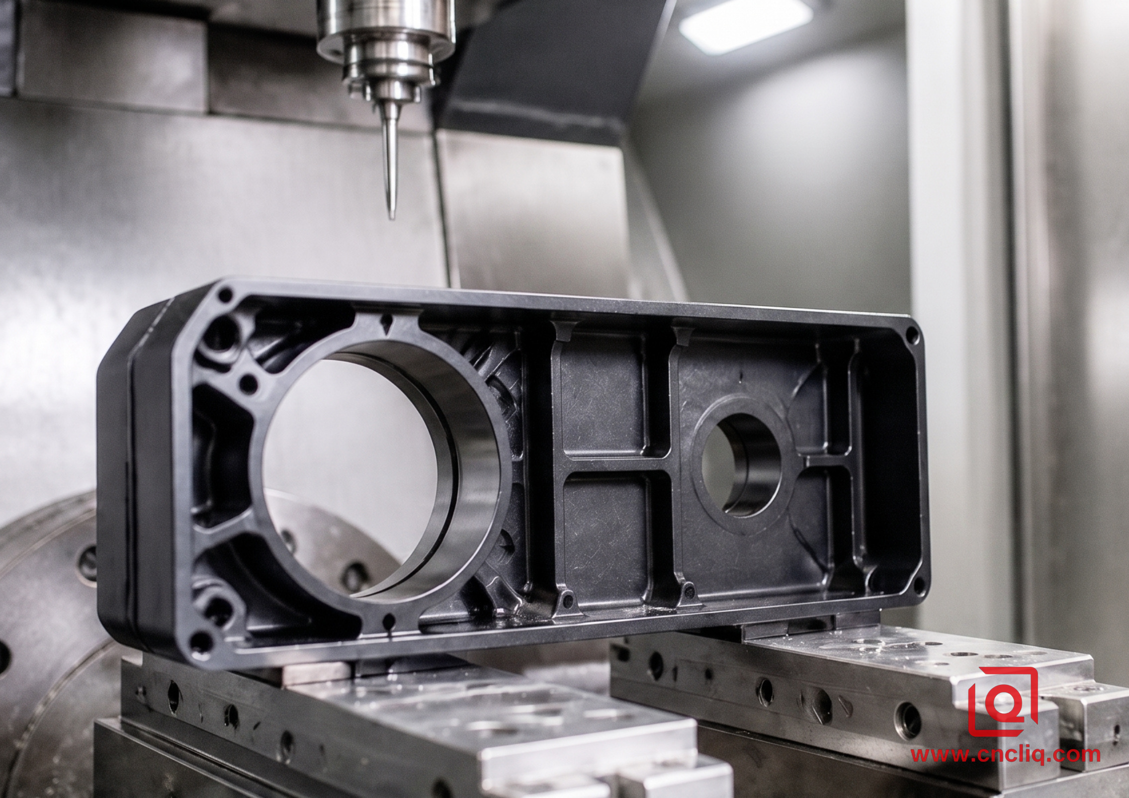
Review this production run for an IP67-rated LiDAR sensor housing to see these principles in action:
-
Material: 6061-T6 Aluminum Solid Billet
-
Envelope Dimensions: 240 mm x 180 mm x 75 mm
-
Key Specs: 1.2 mm thin structural walls, Ra 0.4 µm perimeter O-ring groove, 8 inline M3 stainless inserts, and MIL-A-8625 Type III Hardcoat black anodizing.
Rough 5-Axis Milling -> Stress Relief (160°C / 2 hrs) -> Finish Pass -> CMM -> Type III Anodizing -> Final QC
The Engineering Challenge:
On an earlier prototype run with a past supplier, we watched the thin side ribs pull inward by 0.22 mm the second they unbolted the vacuum table. To make matters worse, the O-ring groove had visible chatter marks that completely blew out our high-pressure helium leak checks.
The Qualified OEM Resolution:
- Dynamic High-Feed Roughing with Stress Relief: We had the shop switch their roughing passes over to dynamic trochoidal milling with a 3-flute carbide tool running at n = 10,000 RPM, vf = 3,200 mm/min, and a light 10% ae radial stepover. Instead of going straight to size, they left 0.8 mm of meat across the profile and baked the batch at 160°C for 2 hours to bleed off internal stress before running final finish passes.
- Harmonic Vibration Damping: To kill resonant chatter on the thin walls, operators clamped tools in rigid hydraulic chucks and ran balanced, variable-helix endmills (38° / 41°). That kept wall squareness locked right within 0.015 mm.
-
Diamond-Burnished O-Ring Track: We stopped chasing micro-leaks by having CAM set up a dedicated PCD form-radius tool just to finish that seal track in one continuous sweep. It knocked down all stepover ridges and left a glass-clean Ra 0.32 µm finish.
-
CMM In-Process Verification: You can't rush metrology. We let the batch sit on the granite plate for a full 4-hour thermal soak at 20°C before running the probe routine—and our 5-axis CMM held true position on every optical sensor bore right inside 0.018 mm against Datum A.
The 200-unit pilot batch achieved a 100% pass rate on helium leak testing with zero assembly fitment issues.
7. Supplier Audit Checklist: 5 Direct Questions to Ask
Before issuing a Purchase Order (PO) or wiring tooling deposits, ask the factory's chief engineer:
-
"What is your standard soak time and thermal stabilization protocol for aluminum parts before CMM inspection?" (Look for an answer specifying a standard 20°C room and at least 2 to 4 hours of thermal equalization).
-
"How do your CAM programmers calculate dimensional offsets for MIL-A-8625 Type III hardcoat anodizing on precision bores?" (They should specify exact radial growth compensation versus silicone masking options).
-
"Can you provide a Gauge Repeatability and Reproducibility (GR&R) report for your bore-gauge and thread inspection setups?" (Verifies their measurement process is stable and independent of operator touch variation).
-
"What fixture strategies do you implement to suppress vibration and spring-back on thin-walled aluminum sections?" (Listen for vacuum chucking, custom support nests, or multi-stage roughing-to-finishing sequences).
-
"How do you trace incoming billet material back to the original melt batch if an anomaly appears post-surface treatment?" (They must show an active barcode/traveler ERP system linked to EN 10204 3.1 MTCs).
FAQs
Q1: What standard dimensional tolerances can a capable aluminum shop reliably hold on production runs?
A: Put a capable machinist behind well-tuned 3-axis or 5-axis spindles, and standard ISO 2768-m linear tolerances are a walk in the park—holding ±0.1 mm across a 30 mm to 120 mm feature is table stakes. If your prints call out tight dowel bores or bearing journals, that's where true shop-floor discipline shows up. If you set up rigid boring bars, run floating reamer holders, and don't skimp on letting parts equalize on the metrology bench, holding ±0.005 mm to ±0.010 mm isn't luck—it lets your operators hit ISO H6/H7 bore tolerances shift after shift.
Q2: How do MIL-A-8625 Type II and Type III hardcoat anodizing mess with part tolerances differently?
A: Type II sulfuric runs a total film of 10 to 25 µm. It splits right down the middle—half bites into the aluminum, and half builds out, so you pick up 5 to 12.5 µm per face (or 10 to 25 µm total on an OD). Type III hardcoat is a whole different beast: it lays down a dense 40 to 60 µm armor, tacking on 20 to 30 µm of solid radial growth on every surface. Critical bearing seats and fine internal threads (such as M3 or M4) must either be masked or pre-machined with CAM offsets to prevent out-of-spec conditions post-plating.
Q3: Why is 20°C (68°F) strictly required for CMM inspection on aluminum parts?
A: Aluminum alloys like 6061-T6 have a high thermal expansion rate (CTE of approximately 23.4 x 10^-6 / °C). On a 500 mm length component, a temperature difference of just 5°C alters the physical measurement by approximately 0.0585 mm (500 mm x 0.0000234 x 5°C = 0.0585 mm). Inspecting warm parts directly off the milling table leads to false pass readings that shrink out of tolerance once cooled to standard ambient conditions.
Q4: What specific quality documentation should be delivered with an aluminum OEM production batch?
A: A complete delivery package from a qualified OEM should include:
- MTCs (EN 10204 3.1): Hard material test certs pinned straight to the melt heat number stamped on each billet.
- FAI Documentation: A signed AS9102 or ISO 9001 First Article pack, matched bubble-for-bubble against the print.
- CMM Data: Full probe logs proving they hit 100% of our designated CTQ callouts across the batch.
- Coating Reports (ISO 2360): Eddy-current test readouts confirming anodize thickness before anything ships out the door.
- Compliance Paperwork: Clean sign-offs on material safety, RoHS, and REACH.
Q5: How do top-tier CNC shops keep thin-walled aluminum parts from potato-chipping on the table?
A: You can't just hog out material and hope for the best. Sharp machinists lean on dynamic trochoidal passes with a light 8% to 15% radial stepover to keep cutting loads down, then pull parts off the mill for a 2-hour stress-relief bake at 160°C. When setting up finish cuts, they clamp stock flat on vacuum fixtures and run variable-pitch carbide mills (38° / 41° helix) to kill chatter and bleed off locked-in stress before taking that final skim.
Summary
A dependable aluminum OEM supplier never hides behind vague marketing claims or generic ISO certificates. They demonstrate active control over metallurgical integrity, thermal stability, tool harmonics, and anodizing offsets. When you lock down your audits with hard CMM probe routines, shop-floor spectrometry, and uncompromising GD&T callouts, offshore sourcing stops feeling like a gamble—it runs as a reliable, tight-tolerance supply loop.
Contact Information
Disclaimer
All technical articles, material specifications, machining recommendations, and surface treatment details published on this blog are for informational and reference purposes only. Please note that general blog insights do not replace signed technical agreements. Because custom parts vary by material heat numbers, machine calibrations, and specific tolerances, binding quality specs are governed solely by your approved CAD drawings, signed contracts, and formal quality plans.
All customer case studies featured on this blog have been thoroughly anonymized and sanitized. The performance metrics, manufacturing workflows, and imagery displayed serve solely to demonstrate our custom machining capabilities and do not represent a single universal standard for all orders.
Liqin Manufacturing Team
Built on 18 years of precision engineering experience, Ningbo Liqin Industry manufactures high-tolerance metal components for demanding global markets. We operate out of a 6,500 m² production hub equipped with over 150 machines, running 4-axis and 5-axis CNC machining, mill-turn machining, cold extrusion, and pressure die casting under one roof. This setup allows us to manage projects seamlessly, taking parts from initial CAD concepts directly to finalized shipments.
We handle quality control with zero compromise. We treat tight tolerances with the engineering discipline they require. Backed by ISO 9001, ISO 13485, and IATF 16949 certifications, our QA engineers run strict IPQC, FQC, and OQC checks on every single production batch. From CMM dimensional mapping and optical profiling to hardness and salt-spray testing, we validate your critical specs upfront—so you receive drop-in ready components with zero assembly headaches or costly line stoppages. On top of manufacturing, you can rely on us for two-hour response times on new RFQs, direct support for prototype sampling, and smooth export shipping across Europe, North America, Asia, and Oceania.
Welcome your inquiries and samples. Visit our website or contact us directly for a competitive quote!
