 English




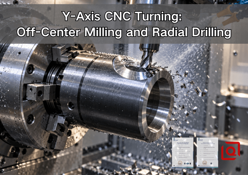
Are you still moving a good turned part to a mill for one offset slot or a few radial holes? The lathe has already established the bore. The seal diameter is on size. Then somebody unclamps the work, wipes a second set of jaws, finds the axis again, and hopes a chip did not settle behind the stop. Small job? On the traveler, yes. On a tight datum chain, not always.
This guide stays by the machine door. What does physical Y travel add? Which eccentric holes need only X and C? Why can a hidden burr matter more than hole diameter? And when should the drawing go to a separate machining center? Valve sleeve on the screen? Sensor body, fitting, shaft, perhaps a small housing? Follow the tool axis before sending the RFQ.
Quick Check at the Drawing
Where do I place the first red mark? On the cutter's centerline. Must that line move above or below the lathe's usual plane? Does the end mill have to draw a real offset rectangle? Does the radial drill need a sideways shift, not merely a new clock angle? Three practical reasons to put Y on the review list.
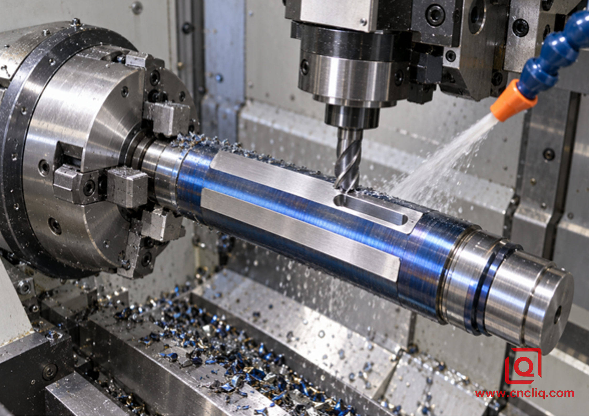
Front-face hole away from center? On the setup sketch, X supplies radius and C supplies clocking. The axial drill advances in Z. Y may sit at zero for the entire cut. One cross-hole running through the normal plane? Index C, then feed a radial live drill in X. “Off-center” tells us where a feature lives. It does not name the machine that must make it.
Where does Y-axis turning make the strongest commercial case? On a mainly round component whose slot, flat, pocket, or port must stay tied to a turned bore, pilot, shoulder, or sealing diameter. Keeping those features in a planned coordinate system can remove a fixture and a datum recovery. It cannot remove tool runout, heat, jaw force, deflection, chips, programming errors, or inspection uncertainty.
What Moves Inside a Y-Axis Turning Center?
Watch the plain two-axis lathe first. Z follows the spindle. X comes in radially. Does the screen show X as diameter or radius? Check the control and its active mode; do not guess from a printout. Here the chuck does the spinning. A stationary insert handles the OD, face, groove, taper, or bore.
Now power a turret station. The cutter spins. Give the main spindle C control: it can stop at a chosen angle or move as part of a path. Give the turret Y: the tool can step across the center plane. Cutoff end still unfinished? An opposing spindle may take the part. Compound cutter angles on the model? That question points toward B, not toward wishful thinking about a simple Y turret.
|
Capability on the quote |
What it really supplies |
Typical use |
What to verify |
|
Axial live tool |
Cutter points along the spindle axis |
Face holes, bolt circles, face slots |
Speed, torque, projection, jaw clearance |
|
Radial live tool |
Cutter points across the spindle axis |
Cross-holes, radial threads, OD flats |
Holder reach, coolant, turret clearance |
|
C-axis |
Controlled spindle angle or interpolation |
Clocked patterns, polar milling |
Indexing method, clamp logic, usable performance |
|
Y-axis |
Independent lateral tool motion |
Offset pockets, true slots, parallel-offset holes |
Travel, work envelope, load, collision clearance |
|
Sub-spindle |
Pickup without a walk to another machine |
Rear thread, rear bore, cutoff face |
Which surface grips, and what datum checks the pickup? |
One label cannot stand in for another. What makes the cutter rotate? Live tooling. What clocks the work? C. What steps the tool off the normal plane? Y. Liqin's live-tooling guide lays out the wider stack. Here, the narrower problem is geometry: when must the tool actually travel in Y?
Does Every Off-Center Hole Need Y?
No. Sketch the tool axis before adding machine cost.
Picture four axial holes on the front face, all on an 18 mm radius. How are they reached? Stop the spindle at each angle, place the drill with X, then feed in Z. Eccentric holes, certainly. Proof of a Y requirement? No.
Now put a hole through the OD. Its centerline crosses the normal X plane and points radially inward. The C-axis clocks the work. A radial live drill feeds in X. Again, Y may add convenience without being essential.
Slide that hole sideways. Its line stays parallel to the first, but it no longer passes through the ordinary cutting plane. Which axis puts the drill on line? Y finally has an unmistakable job. Two side ports at different lateral positions tell the same story. So does an OD slot that a centered radial plunge cannot open to width cleanly.
Why bother with this sketch? Without it, a buyer may fund extra machine time, CAM work, and prove-out although C indexing already fits. The reverse error hurts more. Quote the job on XC, open CAM, then find that the tool line never reaches the feature. The forgotten second operation has just returned.
XY Milling or XC Polar Interpolation?
Can XC mill a face profile? In many cases. The programmer draws a plane; the control turns it into radial travel plus spindle rotation. Centered flats, sensible slots, modest contours—fair work for the method. Near the spindle center, though, the geometry gets awkward. As radius shrinks, a small tangential move asks more of C. Watch a reversal and the finished wall may tell you how the servo behaved.
With a physical Y slide, what is different? Hold C at a known orientation and send the cutter along X and Y. For an offset rectangle, the walls now follow linear moves rather than a continuous X-to-C conversion. Easier to picture? Usually. Free of entry, engagement, stiffness, or travel limits? Certainly not.
The three high-ranking technical pages reviewed here approach that difference from separate shop angles. YAMA SEIKI compares polar interpolation with direct Y and lists travel for individual models. Haas's Y-Axis Lathe Applications Training manual works through G17 axial milling and C alignment. The DS-20Y page then shows one real bundle: Y, C, driven stations, two spindles. What travels from those pages to an RFQ? Only the questions. Which exact machine? Which holder? How much usable travel after clearance? What torque at the intended speed? Which control function and spindle clamp? Numbers belonging to one model stay with that model.
Radial Drilling: Where a Good Hole Can Still Fail

The drill enters cleanly. Diameter passes. Position passes. Is the part finished? Look where the drill breaks into the internal bore.
One edge loses support first. A burr can fold inward. A short chip can hide in the crossing passage. On a fluid fitting, that remnant may cut an O-ring, restrict flow, or return after washing. A vague “deburr all edges” note gives the shop little to measure at a place nobody can see directly.
What belongs on the drawing? Size, depth, position, clock angle, full thread data where needed—and a decision about the crossing edge. Controlled chamfer? Merely no loose burr? A cleanliness check, leak test, or flow check? Name what the assembly needs. Then decide how the shop will prove it.
Then inspect the physical setup. How far does the radial holder project? Does the drill clear the jaw at C90? Where does coolant hit? Where do chips go after the spindle indexes? Did CAM include the holder body, turret face, remaining stock, and adjacent tool stations? Tool-tip simulation alone can miss the collision that stops the machine.
How might the route treat breakthrough? Slow the feed at the right point, come back with a back-chamfer tool, brush the crossing, look with a borescope, wash the passage separately—perhaps one, perhaps several. Which option wins? Ask the alloy, hole size, crossing geometry, and cleanliness note. A feed copied from another job has no vote.
What Happens When the Live Tool Starts Milling?
Does the letter Y turn a driven turret into a VMC? No. Torque at the live station may be modest. The holder can stand well away from its bearings. The chuck supports a part differently from a broad vise or tombstone. Wide, heavy pocketing may still have an obvious home on the mill.
Which features fit naturally? Short keyways, wrench flats, connector slots, shallow face pockets, small bolt patterns, and access holes on a part that remains mostly rotational. Which details raise a flag? Deep narrow slots, sharp internal corners, broad interrupted cuts, large removal volumes, and any path that pushes the tool beyond practical Y travel after cutter radius and lead-in are counted.
Corner radius is not decoration. A zero-radius internal corner cannot come from an ordinary round end mill. What happens when the drawing opens the radius slightly? A larger, stiffer cutter may replace a long fragile one. The cut becomes easier to clear, easier to measure, and often easier to quote.
Surface finish needs the same honesty. Wrench land, seal, bearing location, or cosmetic face—which one is it? The answer changes the pass and the inspection. One blanket roughness value may make the title block tidy while making the quote needlessly untidy.
Put the Three Routes Beside the Print
|
Drawing condition |
C-axis live-tool lathe |
Y-axis turning center |
Separate lathe and mill |
|
Eccentric face-hole pattern |
Often enough |
Also suitable |
Adds a setup |
|
Center-plane radial holes |
Often enough |
Also suitable |
Useful if other milling dominates |
|
Parallel-offset radial holes |
Usually limited |
Strong candidate |
Feasible with a sound fixture |
|
Offset rectangular face pocket |
Possible in selected XC cases |
Direct path often cleaner |
Strong when pocketing dominates |
|
Bore-to-slot position is critical |
Route dependent |
Strong one-grip candidate |
Depends on datum recovery |
|
Broad or deep heavy milling |
Usually weak |
Often limited |
Machining center usually natural |
|
Rear work after cutoff |
Needs another grip |
Sub-spindle may help |
Normal second operation |
|
One forgiving hole on a simple collar |
Adequate |
May be unnecessary |
Simple drill fixture may win |
Look at total process cost. What disappears if the part stays on one machine? A secondary nest, manual loading, another work offset, extra queue time, and one intermediate inspection may disappear. What appears? More CAM work, live holders, collision review, and a longer prove-out. Hourly rate alone cannot settle the choice.
Need a broader equipment comparison? Liqin's guide to 3-axis, 5-axis, and mill-turn machining covers parts that are less rotational. Working on a round housing whose bore controls the rest of the print? The turning-versus-turn-mill guide for concentric housings follows that datum chain.
Building a Stable Y-Axis Process
Can a capable machine rescue a loose plan? No. Walk through the route before opening CAM.
1. Begin at assembly. Which bore locates the component? Which face stops it? Which slot or port controls clocking? Mark those characteristics first.
2. Draw the cutter centerlines. Classify axial drilling, center-plane radial drilling, parallel-offset drilling, direct XY milling, indexed work, and back-working. A missing axis becomes obvious on paper.
3. Draw the grip. Show jaw contact, stop face, bar stickout, cutoff allowance, thin walls, and any cosmetic zone. Will chuck force distort the bore after release?
4. Sequence for stiffness. Rough while the blank can resist load. Open slots and windows later. Should the critical bore be finished before or after interrupted live-tool work? Let part behavior answer.
5. Use the shortest practical tool assembly. Reach that looks comfortable in CAD may chatter once a radial holder, collet, and drill extension are stacked.
6. Simulate more than a colored cutter trace. Where are the chuck, jaws, spindle nose, turret, holder, stock, sub-spindle, and retract path?
7. Prove out deliberately. Check Y centerline, C orientation, tool offsets, clamp commands, safe positions, coolant direction, and chip escape on the exact control and postprocessor.
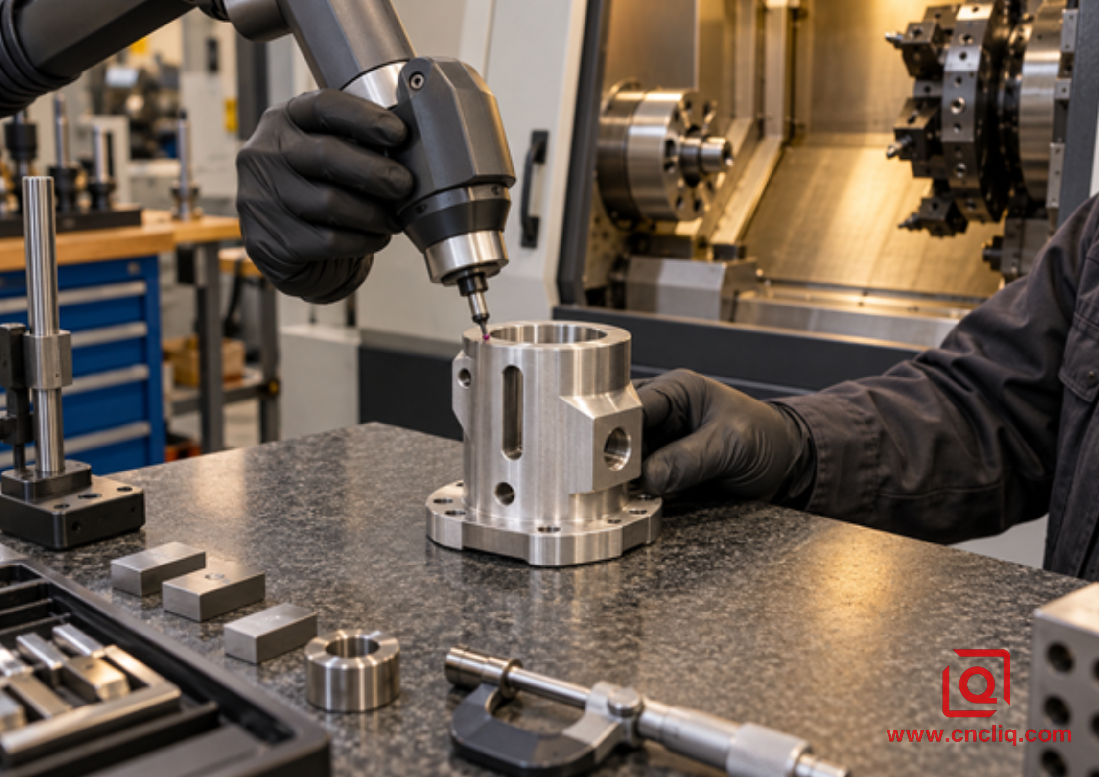
8. Inspect from the drawing datums. A CMM or optical machine should rebuild the functional frame, not use whichever edge is easiest to touch.
9. Freeze what the next batch needs. Which revision, program, jaw set, setup sheet, tools, checks, and reaction limits belong together? Put them under the same job identity.
Need a recognized language for geometry? ISO 1101 and ASME Y14.5 are the usual references, depending on the drawing system. Need a reference for testing NC-axis positioning and repeatability? ISO 230-2 covers that subject. Does any of this stamp a produced part “good”? No. The agreed part inspection still does that work.
Anonymous Composite Case: Offset-Port Sensor Sleeve
An industrial-automation buyer sent a stainless sensor sleeve made from round bar. What was on the sanitized model? A locating bore, external seal diameter, two flats, an offset face slot, three clocked radial holes, and a rear thread. What located the sensor cartridge? The bore. Which details had to follow it? The slot and one passage.
The first routing looked ordinary: turn, then move to a VMC. The problem sat in the second fixture. It would grip a short finished diameter beside a cosmetic surface. A split nest could work, but it would have to recover the bore axis and angular reference every load.
Could the Y-axis route keep the chain shorter? The face slot mapped to direct XY milling. The radial pattern mapped to a radial live tool and C indexing. The rear thread moved to a planned sub-spindle operation. Rough turning came first; live-tool cuts followed while the sleeve retained stiffness; the important bore and seal diameter received their controlled finishing after the heavier interrupted work.
What about the hidden intersection? The plan named breakthrough behavior, deburring, cleaning, and magnified visual inspection. What did the first-article report rebuild? Bore size and form, seal-diameter runout, flat width, slot position from the bore, hole clocking, thread acceptance, and intersection condition.
The revised proposal dropped the milling nest. Must every similar sleeve therefore cost less on Y? No. Program time, batch size, tools, alloy, tolerance, and the available machine get a say. Treat this as a sanitized composite drawn from Liqin's public machining scope. It shows route logic; it neither exposes a customer design nor guarantees an outcome.
DFM Notes From the Mark-Up Desk
· Dimension offset work from functional datums, not from a convenient raw edge.
· Name the governing GD&T standard and use modifiers only when function supports them.
· Give internal pockets a realistic cutter radius.
· Avoid deep narrow slots unless assembly truly requires them.
· Leave tool access beside shoulders, flanges, and chucking areas.
· Define the acceptable condition where cross-holes enter a bore.
· Specify thread form, size, class, depth, and gauge requirement.
· Mark seal, bearing, and cosmetic surfaces separately.
· Send the STEP model for path planning and the controlled 2D print for acceptance.
· Share prototype quantity, repeat release size, and annual demand.
Need a product-side reference? Liqin's custom gearbox output shaft brings turned steps, grooves, flats, heat treatment, grinding, and inspection into one part family. Need the passage problem instead? The custom hydraulic manifold brings ports, threads, crossings, seal faces, cleaning, and verification together. Useful proof of relevant scope, yes. A substitute for marking up your drawing? No.
What Should You Send for a Useful Quote?
Can two suppliers quote the same job from a screenshot? Rarely. Start with the native STEP model and controlled 2D print. Then fill the gaps: alloy and condition, finish, sample and production quantities, annual releases, critical features, inspection paperwork, burr and cleanliness notes, packaging, timing. Miss one and the quotes may describe different parts.
Which three characteristics stop assembly? Circle them. Could a radial port be on size yet misplaced? Yes. Does the face slot carry a connector or merely catch the eye? Say so. Will coating touch the seal diameter? Mark the mask. Clear risk can be planned; hidden expectation tends to come back as a change or rejection.
Turned bore plus offset slots, clocked flats, or radial ports on the print? Send the files through Liqin's contact page. Ask the engineering team to lay three routes beside the datum chain: C-axis live tooling, physical Y, and lathe plus mill. Which one protects function at the lowest total process cost? That is a better RFQ than “quote your lowest Y-axis price.”
FAQ
1. Does every off-center hole require a Y-axis CNC lathe?
No. Front-face hole away from center? X can place the radius, C can clock it, and the axial drill can feed in Z. Cross-hole in the normal plane? A radial live station and C indexing may be enough. When does Y enter? When the tool line needs its own sideways offset, or when a direct XY path makes better sense. Draw that line before naming the machine.
2. Does Y-axis turning automatically beat a lathe-and-mill route on accuracy?
No. What can it remove? One re-clamp and one attempt to recover the datum. That matters when a slot or port points home to a turned bore. What remains? Machine condition, heat, jaw force, runout, load, offsets, and measurement. A careful second fixture can beat a careless “done in one” program.
3. Can a Y-axis turning center replace five-axis machining?
Sometimes, for a narrow class of parts. Is the body mainly round, with reachable holes, flats, slots, or a shallow pocket? Y may be enough. Do cutters need compound angles? Are surfaces broad and sculptured, cavities deep, or milling heavy? Now a B-axis mill-turn or five-axis machining center deserves the conversation. Let access and cutting load lead; axis count follows.
4. What files and notes improve quotation accuracy?
Bring the STEP model and the controlled print. What else? Material and condition, finish, sample and release quantities, annual demand, datum relationships, complete threads, burr and cleanliness criteria, inspection evidence, packaging, timing. Then mark the features that can stop assembly. Without those marks, each shop will quietly price a different assumption.
5. How are off-center slots and radial holes inspected?
Follow the datum scheme. Position and clocking? A CMM or optical system may suit. Thread form? Use the agreed gauge. Related turned diameters? A runout method may answer. Hidden crossing? Magnification or a borescope can look where an outside caliper cannot. Before cutting the batch, agree on the frame, sample rate, report, and what happens after a miss.
Summary
Where does Y earn its keep? On a mostly round part whose offset work must stay tied to a turned datum. Where can it stay idle? Many face holes and center-plane cuts already belong to X, Z, C, and a live station. Parallel-offset holes, true slots, or an awkward XC pocket make the stronger case. Even then, check grip, reach, driven-tool muscle, chips, burrs, simulation, and measurement. Model, print, volume, critical relationships—send those first. Choose the route second.
Contact Information
Company: Ningbo Liqin Industry Co., Ltd.
Daily customer maintenance & after-sales support:service@shturl. zhuwanying@cncliq.com
New inquiry, quotation & order discussion:business@shturl. zhouli@chinaliqin.com
Hotline: +86 18757148656
Disclaimer
All technical articles, material specifications, machining recommendations, and surface treatment details published on this blog are for informational and reference purposes only. Please note that general blog insights do not replace signed technical agreements. Because custom parts vary by material heat numbers, machine calibrations, and specific tolerances, binding quality specs are governed solely by your approved CAD drawings, signed contracts, and formal quality plans.
All customer case studies featured on this blog have been thoroughly anonymized and sanitized. The performance metrics, manufacturing workflows, and imagery displayed serve solely to demonstrate our custom machining capabilities and do not represent a single universal standard for all orders.
Liqin Manufacturing Team
Built on 18 years of precision engineering experience, Ningbo Liqin Industry manufactures high-tolerance metal components for demanding global markets. We operate out of a 6,500 m² production hub equipped with over 150 machines, running 4-axis and 5-axis CNC machining, mill-turn machining, cold extrusion, and pressure die casting under one roof. This setup allows us to manage projects seamlessly, taking parts from initial CAD concepts directly to finalized shipments.
We handle quality control with zero compromise. We treat tight tolerances with the engineering discipline they require. Backed by ISO 9001, ISO 13485, and IATF 16949 certifications, our QA engineers run strict IPQC, FQC, and OQC checks on every single production batch. From CMM dimensional mapping and optical profiling to hardness and salt-spray testing, we validate your critical specs upfront—so you receive drop-in ready components with zero assembly headaches or costly line stoppages. On top of manufacturing, you can rely on us for two-hour response times on new RFQs, direct support for prototype sampling, and smooth export shipping across Europe, North America, Asia, and Oceania.
Welcome your inquiries and samples. Visit our website or contact us directly for a competitive quote!
