 English





Are you still fighting a shaft that measures correctly near the chuck but grows oversize in the middle, chatters during the last pass, or bows as soon as the tailstock pressure comes off? Slender aluminum parts can look simple on a drawing. On the lathe, they behave more like springs. This guide explains why that happens and how engineers, buyers, and machinists can control it before a promising quote becomes a scrap report.

{width=6.1875in height=4.375in}
A slender stepped aluminum shaft supported between the chuck and a live center during CNC turning.
Short answer: chuck-only turning is usually the lowest-risk choice only for relatively short, rigid projections. As the unsupported length increases, plan for a tailstock, a fixed steady rest, a traveling follow rest, a guide-bushing machine, or a staged combination. Use a sharp positive-rake aluminum insert, keep tool overhang short, separate roughing from finishing, and verify straightness after the part has been released and allowed to reach the inspection temperature. Any feed, speed, jaw pressure, or support load must be proved on the actual alloy, temper, geometry, machine, tool, and tolerance.
In today's rapidly evolving manufacturing landscape, precision and efficiency are more important than ever. CNC machining has revolutionized the way complex components are produced, offering unparalleled accuracy, consistency, and flexibility. By leveraging advanced technology and state-of-the-art equipment, manufacturers can optimize every stage of production while minimizing waste and reducing lead times. Moreover, the integration of automation and data-driven insights enables teams to identify potential challenges before they become costly problems. This proactive approach not only enhances product quality but also strengthens customer confidence and supports long-term business growth. Ultimately, choosing the right machining strategy is essential for achieving reliable results in a competitive global marketplace. Whether a company is developing a prototype or scaling to full production, a comprehensive plan helps ensure that every requirement is addressed with care. From material selection and tooling to inspection and delivery, each decision contributes to the success of the finished component.
In modern precision manufacturing, producing a slender aluminum shaft requires more than simply following nominal dimensions. Manufacturers must evaluate material behavior, workholding rigidity, tool geometry, thermal stability, and inspection requirements as part of one integrated strategy. By addressing these factors early, engineering teams can reduce unwanted deflection, prevent chatter, and maintain consistent results throughout production. Moreover, a well-planned process helps control costs by reducing trial cuts, rework, and avoidable inspection disputes. This comprehensive approach supports both rapid prototyping and repeat production while preserving the functional relationship between critical journals, shoulders, and datum features. Ultimately, successful shaft machining depends on close collaboration between designers, buyers, machinists, and quality engineers. When each requirement is clearly defined, the supplier can select an appropriate support method and create a reliable path from raw bar to finished component.
Quick Risk Map for Slender Aluminum Turning
|
Drawing or process signal |
What it can cause |
First engineering response |
Evidence to record |
|
High unsupported L/D ratio |
Barrel shape, taper, chatter, bow |
Add support or shorten the exposed length |
L/D at every operation, not only on the finished part |
|
Large stock removal from one side or one end |
Residual-stress movement |
Rough symmetrically, pause, re-indicate, then finish |
Material form and temper, roughing allowance |
|
Dull or negative cutting geometry |
Higher radial force and built-up edge |
Use sharp, polished, positive geometry for aluminum |
Insert designation, edge condition, chip form |
|
One measurement taken while clamped |
False confidence |
Inspect released, stabilized parts on defined datums |
Temperature, fixture state, instrument and method |
|
Tight diameter but no straightness or runout control |
Function can still fail |
Define the functional datum and geometric requirement |
Datum scheme, straightness, circular runout or total runout |
1. Why a Slender Aluminum Shaft Moves Away from the Tool
During external turning, the insert applies tangential, axial, and radial force components. The radial component is the troublemaker for a thin shaft: it bends the workpiece away from the programmed tool path. Less material is removed where the shaft bends most, so the released part may be largest around the flexible span. If the dynamic stiffness also drops far enough, the tool and shaft begin feeding energy back into each other and chatter replaces a clean spiral feed mark.
Aluminum adds a useful lesson. It is easy to cut, but “easy to cut” is not the same as “hard to bend.” NIST publishes temperature-dependent property data for 6061-T6, and commonly used room-temperature references place its Young’s modulus near 69 GPa. Steel is roughly 3 times stiffer by modulus, so an aluminum shaft of the same geometry is more compliant under the same transverse load. The alloy’s lower cutting force helps, but geometry can overwhelm that advantage. See the NIST 6061-T6 material data for the traceable property source.
The simplest screening metric is:
L/D = unsupported length / smallest effective diameter in that span
Use the dimensions that exist during the operation. A finished drawing may show a 20 mm shoulder, yet the cutting tool may be loading a 10 mm journal 180 mm from the nearest effective support. That operation is governed by an L/D of 18, not 9.
Practical articles often use broad bands: below about 4, chuck-only work can be manageable; from roughly 4 to 12, consider a tailstock; and beyond about 12 to 15, intermediate or traveling support is often required. These are triage rules, not acceptance limits. Tolerance, force direction, stock condition, support stiffness, and machine dynamics can move the boundary.
A Useful Deflection Calculation—With the Right Warning Label
For a solid round treated as a simply supported beam with a midpoint radial load, a first estimate is:
δ = F × L³ / (48 × E × I), where I = π × D⁴ / 64
Here, δ is elastic deflection, F is radial load, L is the span, E is Young’s modulus, and I is the second moment of area. Deflection rises with length cubed and falls with diameter to the fourth power, so a slightly larger journal or shorter span can have an outsized effect.
For a screening example, take a 12 mm solid 6061 shaft with a 180 mm simply supported span, E = 68,900 N/mm², and an assumed 20 N midpoint radial load. I is about 1,018 mm⁴ and calculated deflection is about 0.035 mm. A real chuck-tailstock system is not an ideal beam and the cutting load moves, but the estimate shows why a ±0.020 mm diameter requirement needs more than a nominal offset.
For deeper background, the UTEC guide on steady and follow rests for long workpieces explains the same beam model and support choices. Use that formula to rank risk, then prove the final process with trial cuts and inspection.
2. Read the Error Pattern Before Changing the Program
Start by reading the error shape.
|
Observed result |
More likely causes |
Shop-floor check |
|
Diameter largest near midspan, smaller near supports |
Static workpiece deflection |
Map diameter at several Z positions after release |
|
Nearly linear taper from chuck to tailstock |
Center misalignment, bed geometry, thermal drift, programmed taper |
Turn and measure a test bar; verify tailstock alignment |
|
Repeating waves or a singing cut |
Chatter, support looseness, worn insert, excessive speed |
Note wavelength, spindle speed, chip form, and support condition |
|
3-lobed roundness after unclamping |
Chuck or 3-point support distortion |
Compare in-chuck and released roundness |
|
Shaft is straight while supported but bows when free |
Residual stress, excessive center load, asymmetric stock removal |
Release, stabilize, rotate on V-blocks, and remeasure |
|
Good first pieces followed by drift |
Tool edge pickup, temperature, support wear, bar variation |
Trend diameter, temperature, offsets, and insert life by part |
CNC compensation may correct a stable, measured taper. It cannot repair chatter, a loose support, built-up edge, or variable residual stress.
3. Choose the Support That Matches the Operation
Chuck or collet only
Keep the exposed length short. A collet or well-designed soft jaw can spread force, but grip length and drive torque still matter. Too little grip slips; too much pressure can mark or distort a thin section.
Tailstock live center
A live center closes the free end of a moderately slender solid shaft. Prepare a suitable clean center hole, confirm alignment, and do not replace cutting-force control with excessive tailstock pressure.
Fixed steady rest
A fixed steady rest supports one axial station when the tool works beyond a long overhang or chuck-and-tailstock support leaves a flexible middle span. Its contact band must be round, smooth, concentric, and correctly lubricated. Rollers set on rough or tapered stock can introduce runout and vibration.
Traveling follow rest
A follow rest moves with the carriage and reacts near the cutting zone. Its pads need a suitable surface behind the tool, clean contacts, and controlled load so they do not burnish or score fresh aluminum.
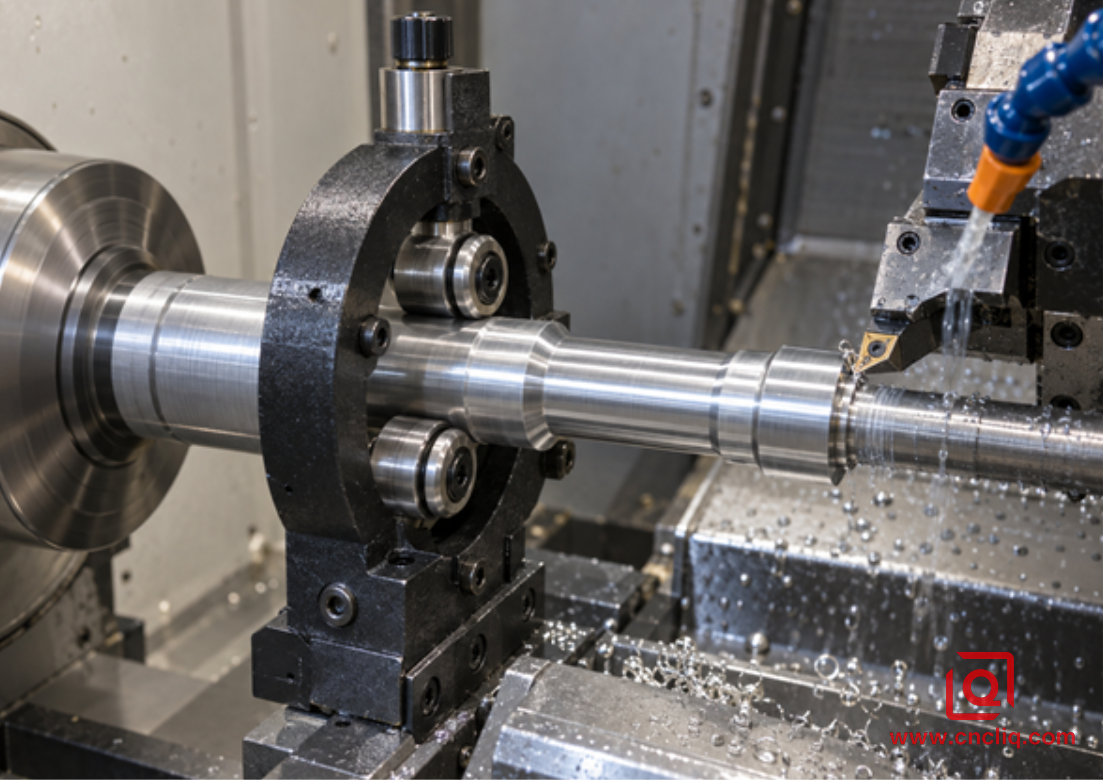
{width=6.1875in height=4.375in}
A fixed three-roller steady rest can shorten the effective flexible span, provided its support journal is true and the contact load is controlled.
Swiss-type or guide-bushing turning
For small diameters and production quantities, a guide bushing can keep the cutting point close to the stock support. It changes the economics and process constraints, however. Bar straightness, guide-bushing clearance, stock consistency, feature order, and surface condition become central. A conventional CNC lathe with a tailstock may be the better prototype route, while a Swiss-type process can become attractive after volume and geometry are stable.
If the shaft also has cross holes, flats, slots, or timed features, compare a conventional turning chain with a single-platform mill-turn route. Our article on CNC turning versus turn-mill machining for concentric aluminum parts explains how datum continuity and secondary setups affect the decision.
4. Reduce Radial Cutting Force Without Creating a New Problem
Support is half the answer. The tool must cut freely without unnecessary force.
1. Use sharp, polished, positive-rake geometry for non-ferrous material. A keen edge shears instead of plowing. Watch for built-up edge, which changes both size and finish.
2. Select nose radius with the feed. A smaller radius can lower passive radial force, but may need a lower feed to meet finish. Follow the insert maker’s data and prove the pairing in a trial.
3. Keep the holder short and on center. Tool deflection adds to workpiece bending; extra overhang and a weak interface reduce the whole system’s stability.
4. Maintain real chip thickness. An overly light skim may rub. The finishing allowance must be large and consistent enough for the edge to cut cleanly.
5. Separate roughing from finishing. Roughing releases stress and creates heat; finishing should begin from a measured, stable condition with known allowance.
6. Direct coolant and manage chips. Prevent aluminum pickup and keep long chips away from the shaft, center, and rest. Use limits approved for the machine, fluid, and tool.
7. Test cutting direction deliberately. Push turning, pull turning, and segmented paths load a shaft differently. Verify clearances and support loads before production release.
Do not copy aggressive parameters from a general aluminum chart into a 20:1 shaft. The OEM aluminum CNC turning alloy guide is useful for comparing alloy and chip behavior, but the slenderness and support system should derate any starting window. Toolmaker recommendations remain the first source for the chosen insert.
5. A Repeatable Process Plan from Raw Bar to Final Size
1. Review by operation. Mark the smallest working diameter, unsupported length, datum axis, finish, geometric controls, threads, coating allowance, no-mark zones, and whether center holes or temporary support journals are allowed.
2. Lock the material definition. “6061 aluminum” is incomplete. Record the approved product form and temper, and do not substitute 6061-T6, 6061-T651, 2024-T351, or 7075-T651 without design approval.
3. Qualify and prepare the bar. Check documentation, damage, size, and straightness where required. Face, center-drill if permitted, prepare grip and support surfaces, and verify runout.
4. Rough without creating a weak span too early. Leave balanced allowance. For high-risk geometry, release or relax the setup after roughing, measure movement, and re-establish the finish datum.
5. Finish under the intended support. Use a controlled edge, consistent allowance, stable temperature, and short effective span. A spring pass may diagnose recovery, but repeated spring passes should not be the main control.
6. Protect, release, and inspect. Support the part during deburring, protect journals, let it stabilize, and measure in the free or drawing-specified state used for acceptance.
6. Inspection Must Separate Size, Form, and Datum Error
This proactive approach not only enhances product quality but also strengthens customer confidence and supports long-term business growth. A part can be on size at every station and still have a curved axis. It can also be straight but show runout because the datum centers or mounting journals are not coaxial.
For a practical shop check, support the shaft on suitable precision V-blocks or between defined centers, rotate it slowly, and traverse a dial indicator along the specified surface. Record the support condition and indicator locations. For higher requirements, use equipment and methods that match the drawing and quality plan. ISO 230-1 addresses geometric accuracy tests for machine tools; drawing requirements for surface texture now sit in the ISO 21920 series, which replaced the withdrawn ISO 1302:2002. The current status matters when an RFQ references an older standard.
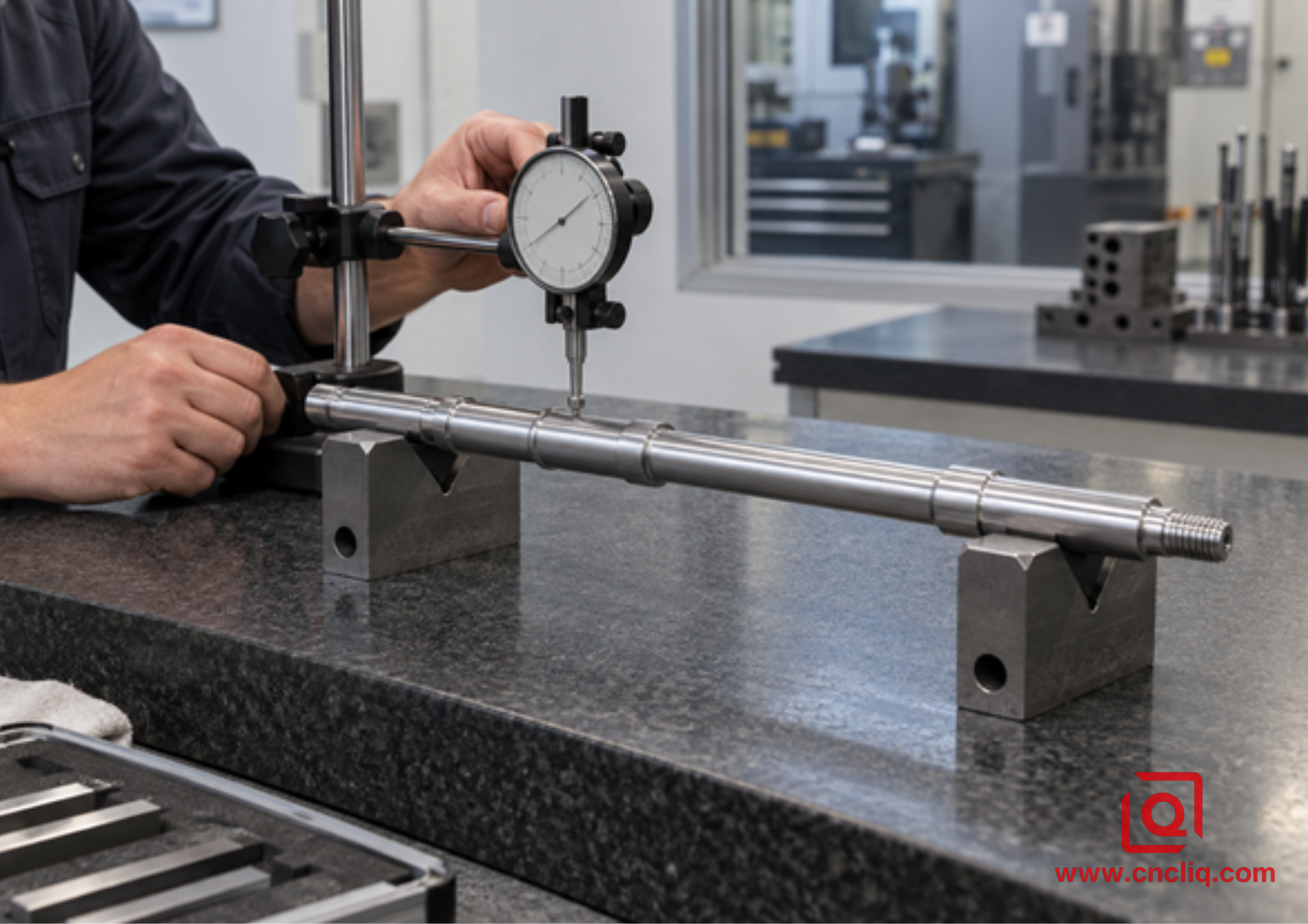
{width=6.1875in height=4.375in}
Released-part inspection on defined supports helps distinguish diameter variation from bow and datum-related runout.
Temperature belongs in the record when tolerances are tight. Aluminum expands approximately 23 × 10⁻⁶ per kelvin around room temperature. A uniform 10°C change over a 200 mm length represents roughly 0.046 mm of length change. That calculation does not predict a real part’s temperature field, but it explains why a warm shaft should not be rushed from the spindle to final acceptance.
7. An Anonymized Buyer Case: Long Sensor-Drive Shaft
The following composite case is anonymized and sanitized to illustrate process planning; dimensions and results are representative, not a universal production promise.
A motion-control buyer requested a 214 mm long 6061 shaft for a compact sensor-drive assembly. Its smallest continuous journal was 10 mm, between larger bearing and coupling seats. The drawing specified a 0.020 mm diameter tolerance on the bearing seat, 0.030 mm total runout to datum A, Ra 1.6 µm on the journal, a threaded end, and a cross hole. A small validation lot came before moderate annual demand.
During finishing, the effective L/D around the 10 mm span exceeded 20. The proposed plan therefore used a customer-approved center feature, tailstock-supported roughing, a true support journal, staged stock removal, and supported finishing with positive-rake tooling. The part was released before straightness and runout checks; cross-hole work followed only after the turned axis passed. The report listed diameter stations, runout at both seats, surface finish, material-certificate status, and the pre-coating condition.
Instead of asking only, “Can you hold ±0.010 mm?”, buyer and supplier could agree on support features, datum sequence, measurement state, prototype quantity, and approval evidence before tooling. A relevant example of broader shaft capability is the custom precision gearbox output shaft product page; alloy, geometry, and acceptance criteria still follow each approved drawing.
 {width=6.1875in height=4.375in}
A small validation lot lets the process team prove support, cutting, and inspection decisions before volume production.
8. What to Put in the RFQ for a Faster, More Defensible Quote
Send more than a cropped PDF. A good slender-shaft package includes:
· 3D model plus a controlled 2D drawing with revision level;
· complete aluminum grade, temper, product form, and approved substitution rules;
· annual volume, first-lot quantity, and expected delivery cadence;
· functional datum scheme and the features that mate with bearings, seals, couplings, or sensors;
· diameter, straightness, circular runout or total runout, and surface-texture requirements where function needs them;
· whether center holes, support journals, or temporary process features are allowed;
· coating or anodizing requirements, masked areas, and whether dimensions apply before or after finishing;
· required records such as material certificates, first article, CMM or profilometer data, and lot traceability;
· packaging rules that prevent long parts from bending or striking each other in transit.
If material choice is open, review the aluminum material and product category and state the load, environment, finish, and regulatory needs. For process comparison, see choosing 3-axis, 5-axis, or mill-turn for custom aluminum parts.
Main B2B Keywords and Buyer Intent
|
Keyword |
Likely intent |
Best conversion response |
|
CNC turning slender aluminum shafts |
Technical and supplier research |
Explain deflection controls and request a drawing |
|
custom aluminum shaft machining |
Commercial investigation |
Show material, turning, secondary, and inspection scope |
|
long shaft CNC turning service |
Supplier selection |
Confirm machine envelope, support route, tolerance and volume |
|
precision aluminum shaft manufacturer |
Vendor qualification |
Provide certifications, inspection plan and traceability options |
|
prevent shaft deflection during turning |
Problem-solving |
Diagnose L/D, cutting force, support and error signature |
|
aluminum shaft machining quote |
Transactional |
Ask for CAD, tolerances, quantity, material and finish |
|
CNC turned aluminum parts supplier |
Broader sourcing |
Link turning capability to part-specific DFM review |
|
low-runout aluminum shaft machining |
High-intent technical sourcing |
Define datum, inspection state and runout method before pricing |
If your shaft drawing is already available, send the STEP file, 2D drawing, material condition, quantity, and the 3 most critical features. Liqin’s engineering team can review the likely deflection points, support strategy, inspection route, and cost drivers before a quotation is finalized. That conversation is more valuable than a low unit price built around an undefined process.
FAQs
1. At what L/D ratio does an aluminum shaft need tailstock or steady-rest support?
There is no universal cutoff. An L/D below about 4 is often treated as relatively rigid, roughly 4 to 12 deserves a tailstock and process review, and above about 12 to 15 commonly pushes the job toward intermediate or traveling support. Those bands are screening guidance only. The actual decision also depends on the smallest working diameter, radial cutting force, tolerance, stock straightness, center alignment, tool geometry, feature sequence, and whether the dimension is checked while supported or after release.
2. Can a CNC offset compensate for slender-shaft deflection?
A CNC offset or programmed taper can correct a stable, repeatable error pattern after measurement, but it should not be the first response to an unstable mechanical system. Compensation cannot repair chatter, changing built-up edge, loose support, variable bar stress, or heat drift. First make the setup repeatable, map the diameter along Z, confirm the datum and inspection state, and then use a limited compensation only if the residual error is consistent across parts and lots.
3. Is 6061-T651 always better than 6061-T6 for a long turned shaft?
No. T651 identifies a stress-relieved condition associated with specific product forms, while T6 is a broader precipitation-hardened temper designation; availability and allowable design properties depend on the material specification and product form. A supplier must not substitute temper based on a blog rule. Put the required specification, form, and temper on the drawing, review residual-stress risk with the material source and machine shop, and obtain design approval for any change.
4. Should straightness and runout both appear on the drawing?
Only when both control different functional needs. Straightness controls the form of a line element or derived axis without necessarily referencing another datum. Runout controls variation as the part rotates about a specified datum axis and therefore combines several geometric effects. A bearing seat, seal journal, and coupling may need a datum-related runout requirement, while a long free span may also need straightness. The design engineer should define the functional datum structure and avoid duplicate controls that add cost without protecting assembly.
5. What information is needed to quote a precision aluminum shaft?
Provide the STEP model, revision-controlled 2D drawing, complete alloy and temper, raw-material form if important, annual and first-lot quantities, critical diameter and geometric tolerances, surface texture, thread standard, coating, datum scheme, center-hole permission, inspection documents, and packaging expectations. Also identify what the shaft mates with and which 3 characteristics would stop your assembly if they failed. That context lets the supplier choose support, operation sequence, inspection method, and prototype plan instead of pricing hidden assumptions.
Summary
Slender aluminum shaft turning is a stiffness problem before it is a feed-and-speed problem. Calculate the working L/D ratio, recognize that deflection scales with length cubed and diameter to the fourth power, diagnose the error shape, and place support where the cutting force enters the part. Combine a true chuck or collet setup with the right tailstock, steady rest, follow rest, or guide bushing; use sharp positive tooling and a finish allowance that still cuts; then inspect the released part on defined datums at a controlled temperature. A complete RFQ makes those controls quotable and gives both buyer and supplier a clear path from prototype to stable production.
Contact Information
Company: Ningbo Liqin Industry Co., Ltd.
Daily customer maintenance & after-sales support:service@shturl. zhuwanying@cncliq.com
New inquiry, quotation & order discussion:business@shturl. zhouli@chinaliqin.com
Hotline: +86 18757148656
Disclaimer
All technical articles, material specifications, machining recommendations, and surface treatment details published on this blog are for informational and reference purposes only. Please note that general blog insights do not replace signed technical agreements. Because custom parts vary by material heat numbers, machine calibrations, and specific tolerances, binding quality specs are governed solely by your approved CAD drawings, signed contracts, and formal quality plans.
All customer case studies featured on this blog have been thoroughly anonymized and sanitized. The performance metrics, manufacturing workflows, and imagery displayed serve solely to demonstrate our custom machining capabilities and do not represent a single universal standard for all orders.
Liqin Manufacturing Team
Built on 18 years of precision engineering experience, Ningbo Liqin Industry manufactures high-tolerance metal components for demanding global markets. We operate out of a 6,500 m² production hub equipped with over 150 machines, running 4-axis and 5-axis CNC machining, mill-turn machining, cold extrusion, and pressure die casting under one roof. This setup allows us to manage projects seamlessly, taking parts from initial CAD concepts directly to finalized shipments.
We handle quality control with zero compromise. We treat tight tolerances with the engineering discipline they require. Backed by ISO 9001, ISO 13485, and IATF 16949 certifications, our QA engineers run strict IPQC, FQC, and OQC checks on every single production batch. From CMM dimensional mapping and optical profiling to hardness and salt-spray testing, we validate your critical specs upfront—so you receive drop-in ready components with zero assembly headaches or costly line stoppages. On top of manufacturing, you can rely on us for two-hour response times on new RFQs, direct support for prototype sampling, and smooth export shipping across Europe, North America, Asia, and Oceania.
Welcome your inquiries and samples. Visit our website or contact us directly for a competitive quote!
