 English





Are you still fighting an aluminum shaft that measures correctly at the machine, then misses size after it cools—or a thin sleeve that becomes slightly three-lobed as soon as the chuck opens? This guide explains how a production team turns a tight diameter from a risky print requirement into a controlled, measurable process. It is written for engineers, buyers, and quality teams who want useful answers before they send an RFQ, approve a sample, or release a batch.
Aluminum is often described as easy to machine. It is fast to cut, but it is not automatically easy to hold to a narrow diameter band. The material expands more with temperature than steel, its relatively low elastic modulus makes it sensitive to clamping force, and many grades encourage built-up edge when the insert, speed, or lubrication is wrong. Add a long overhang, a thin wall, an interrupted groove, or a post-machining coating, and a simple Ø25.000 mm callout can become the hardest feature on the drawing.
The practical rule: a tight turned diameter is not created by the last tool pass alone. It is the result of a closed loop connecting the drawing, bar condition, machine state, workholding, cutting edge, temperature, measurement method, and reaction plan.
1. Start with the Function, Not a Blanket Tolerance
Before discussing microns, ask what the diameter does. Is it a bearing seat, a seal land, a sliding guide, a press-fit spigot, a cosmetic register, or only a clearance surface? A buyer who marks every diameter ±0.005 mm may believe the drawing is safer. In practice, that choice can require extra finishing passes, controlled inspection, more frequent insert changes, slower sampling, and a higher scrap reserve without improving the assembly.
A functional review should connect each critical diameter to its mating part, fit condition, surface texture, geometric controls, and inspection state. Diameter size cannot carry every requirement. A shaft may be within its two-point size limits yet still fail because of roundness, cylindricity, taper, or runout. Conversely, a supplier should not silently substitute a concentricity assumption for a stated runout requirement. Put the datum structure and the feature relationship on the drawing.
|
Drawing question |
Why it changes the turning plan |
What to send with the RFQ |
|
What mates with this diameter? |
Clearance, transition, and interference fits need different process margins. |
Mating nominal size, fit intent, and assembly method. |
|
Is size required before or after coating? |
Anodizing or plating changes the final surface and may need masking or an agreed allowance. |
Finish specification and the inspection stage. |
|
Does the diameter share a datum with a bore or face? |
One-setup machining can protect coaxiality and runout. |
Datum scheme and applicable GD&T callouts. |
|
How will the customer verify it? |
A micrometer, air gauge, bore gauge, roundness machine, and CMM do not sample the same way. |
Gauge type, measurement locations, and acceptance rule. |
|
What volume is expected? |
A prototype may use direct correction; production needs wear limits and SPC. |
Prototype, annual volume, lot size, and capability target. |
If alloy choice is still open, review the machining and finishing trade-offs first. Liqin’s guide to choosing aluminum alloys for CNC turning provides useful context, while the comparison of 6061 and 7075 for OEM machining helps teams separate strength requirements from manufacturability and finish requirements.
2. Build a Real Diameter Error Budget
A process is easier to control when the tolerance is divided into causes rather than treated as one mysterious number. The exact allocation must come from the part, machine, and gauge study, but the structure is broadly useful: machine repeatability, workholding distortion, tool-edge change, thermal shift, material relaxation, and measurement uncertainty all consume part of the tolerance window.
For a feature with a total tolerance of 0.020 mm, it would be careless to let the machining process use nearly the full 0.020 mm and hope inspection sorts the rest. The shop needs an internal control band narrower than the print tolerance, plus a reaction threshold that triggers an offset or tool change before nonconforming parts are produced. The chosen band should be supported by first-article evidence and, for ongoing production, by actual process data.
|
Variation source |
Typical shop-floor symptom |
Control method |
|
Thermal growth |
Parts trend smaller after cooling, or 2 gauges disagree at different temperatures. |
Stabilize machine and coolant; record part and room temperature; inspect at an agreed reference condition. |
|
Chuck or collet force |
Round in the fixture, lobed or oval after release. |
Use bored soft jaws, a collet, or a full-wrap mandrel; qualify pressure; measure free-state geometry. |
|
Built-up edge |
Diameter jumps, finish turns cloudy, and the edge carries smeared aluminum. |
Use a sharp positive geometry, suitable grade or coating, correct speed, and reliable lubrication or coolant delivery. |
|
Tool or boring-bar deflection |
Taper develops along the length; spring passes change size unexpectedly. |
Shorten overhang, improve support, use repeatable stock allowance, and avoid an ineffective rubbing pass. |
|
Material stress release |
Thin rings change size after part-off or after the part rests. |
Separate roughing and finishing, leave balanced stock, and verify after unclamping and stabilization. |
|
Gauge variation |
Operators obtain different results on the same component. |
Define contact force, orientation, locations, master setting, and a gauge R&R study where appropriate. |
3. Temperature Can Use the Tolerance Before the Tool Does
The NIST-hosted reference Machining of Aluminum and Aluminum Alloys gives a coefficient of thermal expansion range of approximately 18–25 µm/m·K for aluminum alloys and notes that finished parts must be kept cool for dimensional accuracy. ISO 1:2022 specifies 20°C as the standard reference temperature for dimensional and geometrical properties. Those 2 facts explain why a hot part checked beside a lathe can disagree with the same part checked later in a controlled inspection area.
Use the first-order relationship ΔD = α × D × ΔT. For a 100 mm aluminum diameter, using α = 23 µm/m·K as an engineering example, a 5°C temperature difference corresponds to about 0.0115 mm of diameter change. That is not a promise of exact behavior for every alloy or geometry; it is a warning that temperature can consume more than half of a 0.020 mm tolerance band. Use the certified alloy data and the actual measured temperature when a correction is needed.
A robust routine is simple. Warm the machine to a repeatable state. Keep coolant temperature and concentration controlled according to the equipment and fluid supplier’s guidance. Do not lay precision parts on a sunlit bench or a cold steel cart. Let the component and master reach an agreed condition before final acceptance. Record the condition on the inspection report when the diameter is genuinely tight.
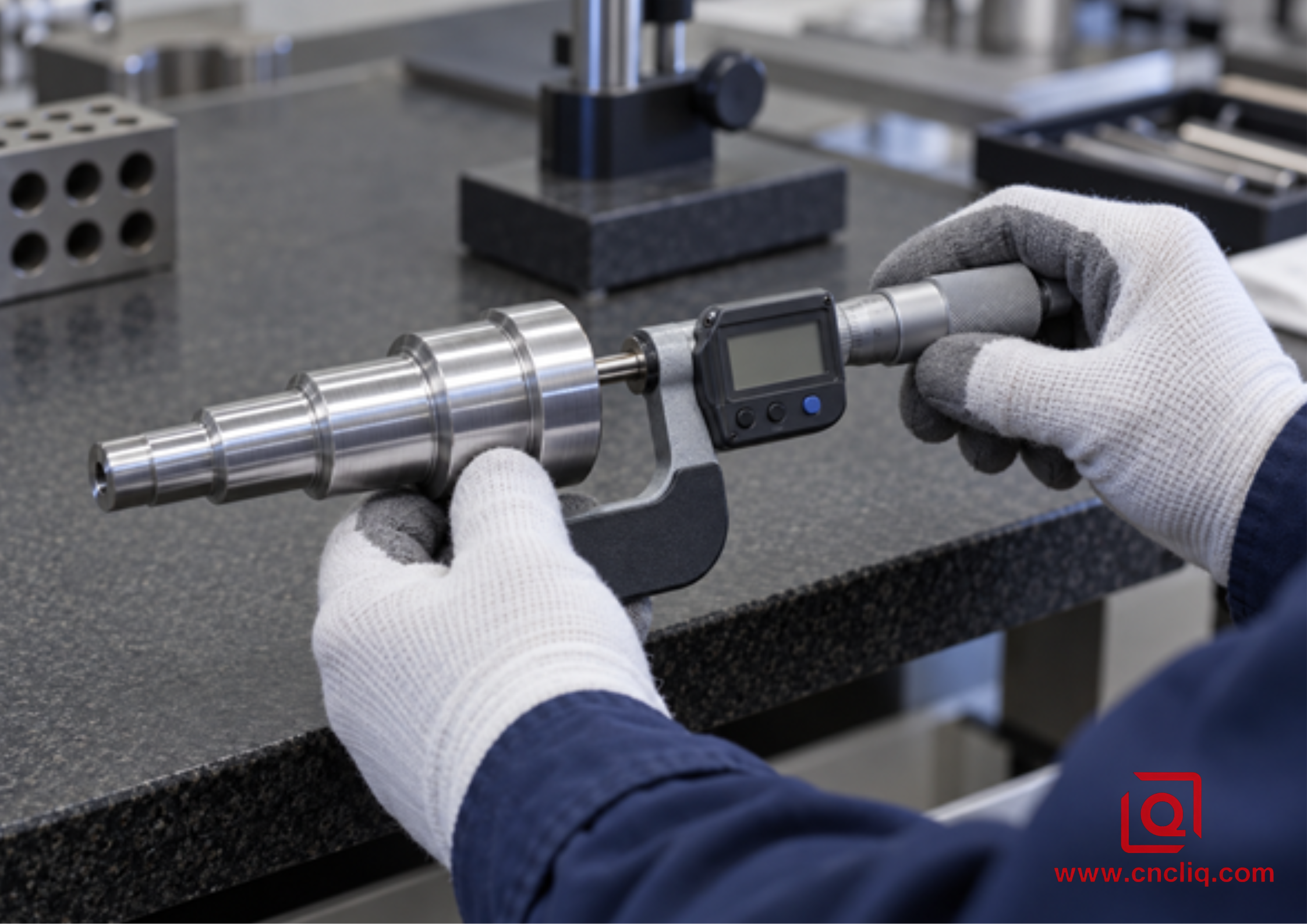
Micrometer inspection of a turned aluminum shaft
Image 1 — outside micrometer verification after the part and gauge have stabilized
4. Workholding: Hold the Part Without Machining the Clamp Error Into It
Aluminum’s elastic modulus is about 70 GPa, and the NIST machining reference warns that aluminum distorts more than many metals under a given chucking force. More pressure is therefore not automatically more secure. On a thin ring, 3 hard jaws can temporarily create a 3-lobed shape. The tool cuts a round path while the ring is constrained; when the jaws open, the component springs toward its original shape and the bore or outside diameter changes.
Use the largest practical contact area. Bored soft jaws should match the grip diameter and hold near a structurally stiff region. Split collets distribute force more evenly than small jaw contacts. Expanding mandrels can support a finished bore while an outside diameter is turned, but their expansion must also be controlled. For very delicate sleeves, a sacrificial support plug or purpose-built arbor may be justified. Whatever the method, validate it at the lowest pressure that prevents slip under the planned cutting load.
Do not accept a tight diameter only while the component remains clamped. Inspect it after release, then rotate it and sample several angular positions. If the wall is thin, repeat the check after a defined stabilization period. This is the difference between measuring the manufacturing fixture and measuring the customer’s part.
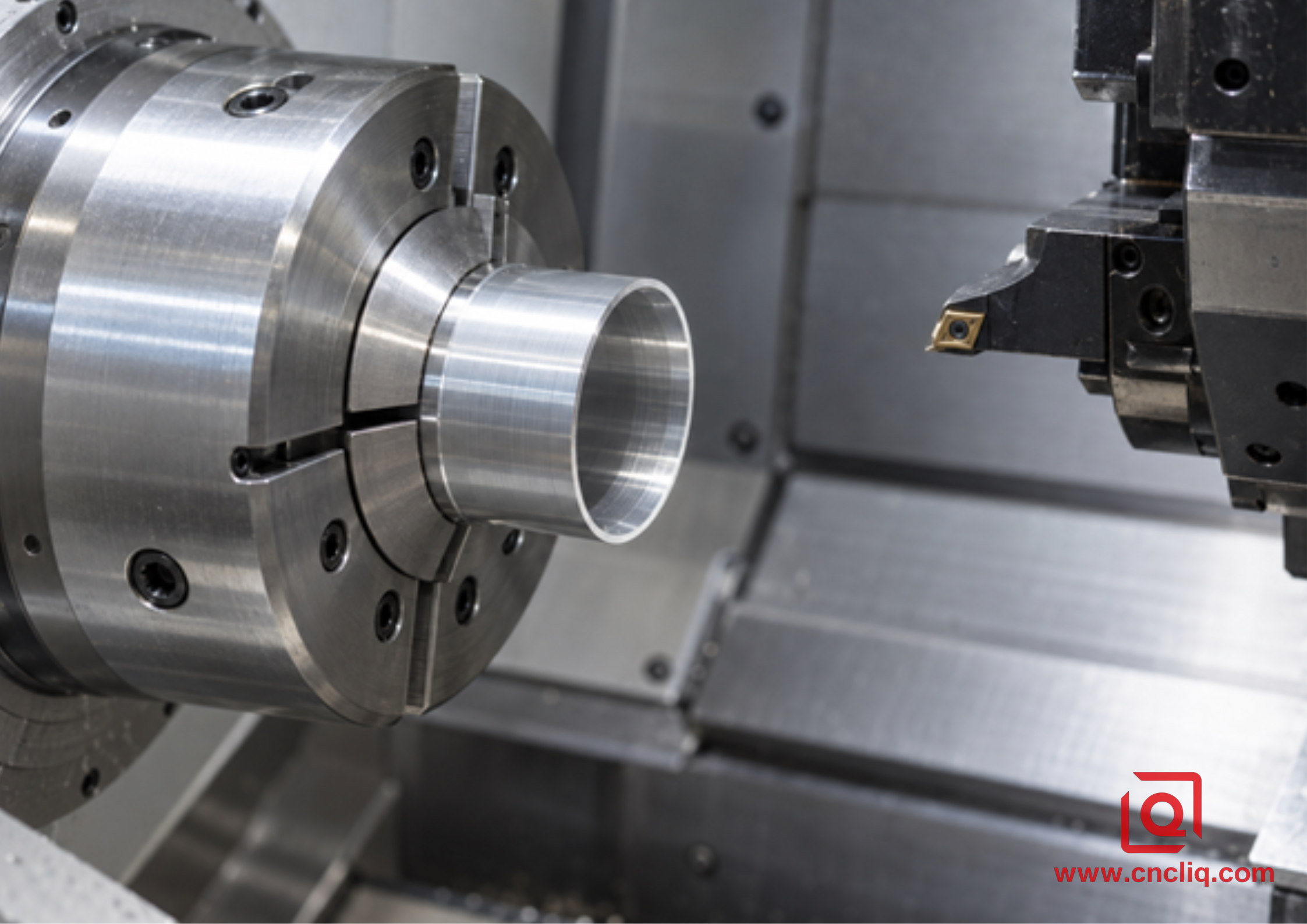
Thin aluminum sleeve held in full-wrap soft jaws
Image 2 — full-contact workholding reduces local distortion on thin-wall turned components
5. Separate Roughing, Semi-Finishing, and Finishing
Trying to reach size in 1 heroic pass makes troubleshooting difficult. A controlled route creates a stable surface and a predictable amount of material for the finish edge to remove.
1. Rough consistently. Remove the bulk material with a tool and geometry intended for the load. Leave enough radial stock to clean up runout, damaged stock surfaces, and distortion from the first operation.
2. Release and reassess when geometry demands it. A thin sleeve or heavily relieved shape may move after roughing. Unclamping, resting, and re-establishing the datum can be worth more than a final correction made against a stressed part.
3. Semi-finish with a repeatable allowance. Establish the shape that the finishing tool will actually see. Unequal stock produces unequal cutting force and can turn a diameter correction into taper.
4. Finish with the correct edge. Sandvik Coromant turning guidance distinguishes sharp finishing geometries for light cuts from stronger roughing geometries. A heavily honed roughing edge used for a tiny finishing allowance may rub, create heat, and leave a poor surface instead of cutting cleanly.
5. Verify before the batch runs away. Measure the first component in a stable state, correct only the demonstrated error, and lock the reaction plan for subsequent checks.
The last pass must be large enough for the edge to cut, but not so large that cutting force deflects the component. There is no responsible universal feed, speed, or depth-of-cut value for every alloy, insert, diameter, and machine. Start with the toolmaker’s data for the exact insert and alloy group, then prove the setting on the actual setup. A good supplier can explain the reasoning and show the first-article result instead of quoting 1 magic number.
6. Keep the Cutting Edge Clean and Predictable
Built-up edge is a common cause of sudden diameter change in ductile aluminum. Material adheres to the rake face and temporarily changes the effective cutting edge. The part may grow, the finish may look torn, and a later piece may shift again when the deposit breaks away. A polished, sharp, positive-rake geometry designed for aluminum reduces cutting force and discourages adhesion. Coolant or minimum-quantity lubrication must reach the tool–chip interface consistently, subject to the machine and fluid supplier’s recommendations.
Chip control also protects the measured surface. Long ribbon chips can wrap around a shaft, scratch a seal land, or disturb coolant delivery. A chipbreaker must be matched to the actual feed and depth of cut; choosing one by insert shape alone is not enough. Watch the chips, surface, spindle load, and insert under magnification. They are early warnings, not housekeeping details.
For long slender shafts or deep bores, reduce leverage before changing offsets. Shorten tool overhang, support the work when practical, and keep the cutting direction and stock allowance consistent. An offset cannot correct a process that bends differently on each part.
7. Measure Diameter as a System
A digital micrometer is not automatically a complete acceptance system. Define where the operator measures, how many angular positions are sampled, how close the points are to shoulders, and whether the stated result is size, ovality, or taper. Use a calibrated master appropriate to the range, keep contact faces clean, and avoid warming a small aluminum part in a bare hand.
For high-volume outside diameters, a snap gauge or electronic comparator can provide fast comparative measurement after it is set with traceable masters. Air gauging is especially useful for bores, but nozzle arrangement, surface finish, and master quality matter. A CMM is valuable for datum relationships and a documented dimensional map; it is not always the fastest or most informative tool for every simple turned diameter. Where form is critical, a roundness instrument or a defined multi-section scan may be required.
Liqin’s article on CMM inspection for aluminum tolerance verification explains how dimensional reporting fits into the wider quality loop. For a turned feature, the measurement plan should still match the functional question rather than defaulting to the most expensive instrument.
|
Feature risk |
Useful inspection approach |
Important caution |
|
Short rigid outside diameter |
Outside micrometer or comparative snap gauge |
Sample at more than 1 angle if lobing is possible. |
|
Thin-wall sleeve OD or ID |
Low-force comparative gauge plus free-state form check |
Gauge force and fixture support can distort the part. |
|
Long bearing journal |
Measure several axial sections and angular positions |
A single mid-length reading will not reveal taper or barrel shape. |
|
Bore related to an external pilot |
Bore or air gauge for size; CMM or runout setup for relationship |
Size alone does not prove coaxiality. |
|
Production batch |
Defined sampling plus SPC on the critical characteristic |
Do not adjust from 1 noisy reading; use a reaction rule. |
8. Use SPC to Correct Drift Before It Becomes Scrap
Tool wear and thermal drift tend to move; random gauge noise tends to scatter. Plotting the critical diameter in sequence helps the team tell the difference. Begin only after the measurement system is acceptable. Then establish the process center from proven parts, set warning and action rules, and document who may change an offset.
A capable process is not the same as a machine that once made 1 good part. Capability indices such as Cp and Cpk summarize variation relative to specification, but they are meaningful only when the process is stable and the data distribution and sampling plan are appropriate. Buyers should ask for the first-article report, control-plan frequency, gauge identification, and reaction plan before asking for a capability number with no context.
For repeat orders, record the bar lot, insert identity, offset history, chuck pressure setting, coolant condition, machine, operator, and gauge. That record turns the next setup into a controlled restart rather than a new experiment.
9. Account for Secondary Operations and One-Setup Relationships
If a diameter will be anodized, plated, heat treated, or assembled with an insert, define whether the print limits apply before or after that operation. Coating thickness and dimensional effect depend on the specified process and supplier. Do not copy a generic allowance from another job. Agree on masking, pre-coat target, sample coupons if needed, and final verification.
When an outside pilot, bearing bore, and sealing face must share an axis, turning them in 1 setup can reduce re-clamping error. Mill-turn equipment is valuable when a primarily rotational part also needs cross-holes, flats, or milled features; the design logic is covered in traditional CNC versus mill-turn machining. The process should be chosen from datum relationships and production needs, not from machine branding.
Anonymous Composite Case: Aluminum Motor-End Interface
The following is an illustrative, anonymized composite case created from common turning practice and Liqin’s publicly listed motor-component capabilities. It is not presented as a record of 1 customer order or as a guaranteed result.
An industrial automation customer needed an aluminum end component with a central bearing bore, an external locating pilot, and a face controlling assembly runout. Early samples from a multi-setup route showed a familiar pattern: the bore met its 2-point size limit, but the pilot-to-bore relationship shifted after re-clamping. The thin surrounding wall also responded to high jaw pressure, so readings taken before release did not represent the assembled condition.
The process team changed the plan rather than chasing offsets. The bearing bore, locating pilot, and critical face were finished from 1 datum in 1 turning setup. Full-contact soft jaws were bored to the actual grip diameter, and the qualified clamping pressure was recorded. Roughing and finishing used separate edges. After machining, the part was released, stabilized, then checked at multiple sections and angles; the datum relationship was verified with a suitable runout or coordinate measurement routine.
This reasoning closely matches the published manufacturing logic for Liqin’s precision motor flange/front end cap, whose bearing bore, locating spigot, and face require controlled concentricity and perpendicularity. A related servo motor front cover also shows why circular interfaces and assembly datums deserve targeted machining and inspection. The commercial lesson is straightforward: if your drawing identifies the mating function and datum relationship at quotation stage, the supplier can design the setup around it instead of discovering the problem during assembly.
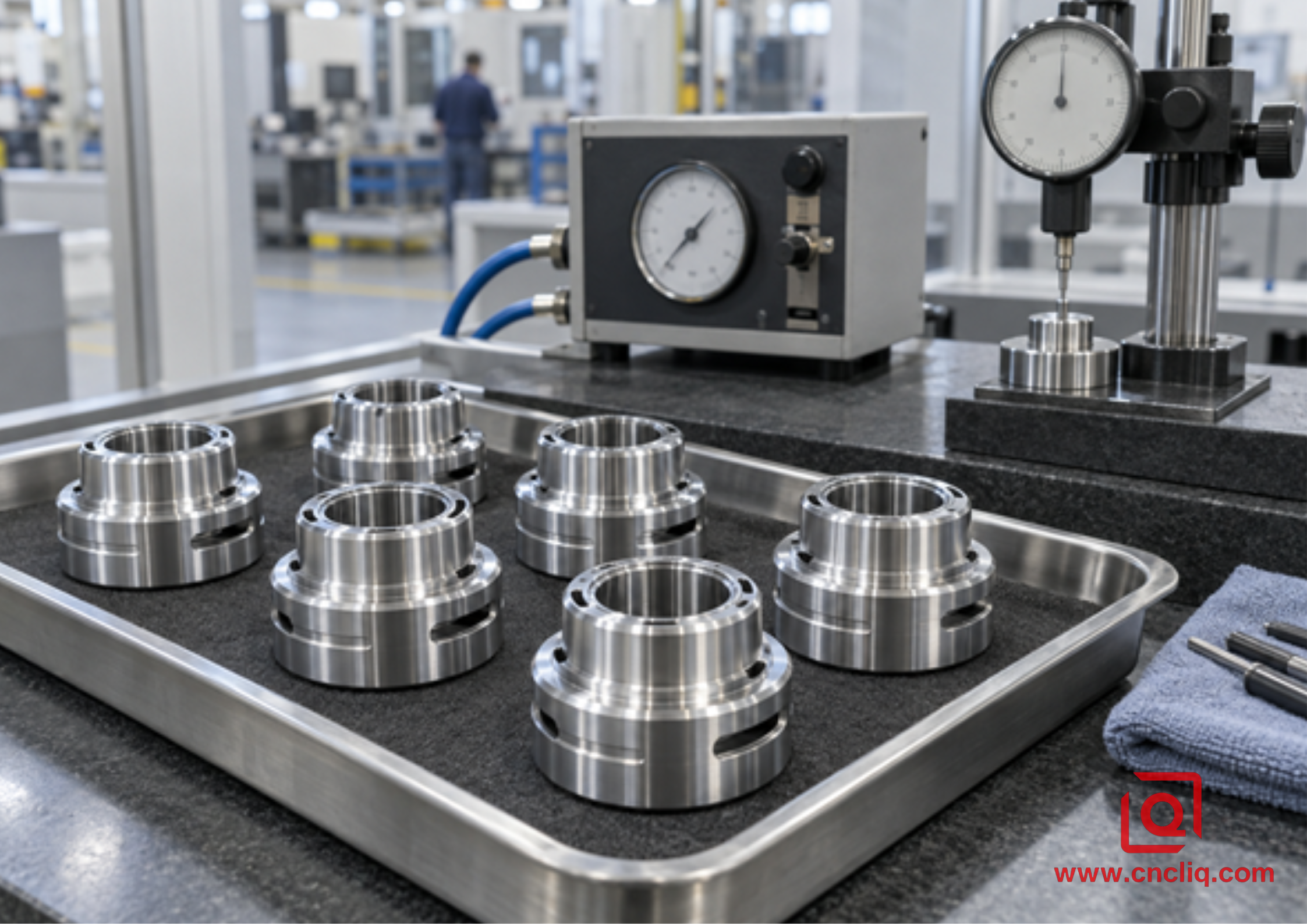
Batch of precision turned aluminum components in inspection
Image 3 — batch control links repeatable turning with appropriate comparative and geometric inspection
RFQ Checklist for Tight-Tolerance Aluminum Turning
Send enough information for the factory to quote the process, not just the shape. A useful package includes:
· Native 3D model and a controlled 2D drawing with revision level.
· Complete alloy and temper, plus any material certification requirement.
· Critical diameter limits, fit function, datum structure, GD&T, and surface texture.
· Whether dimensions apply before or after anodizing, plating, heat treatment, or assembly.
· Mating-part information where fit or stack-up drives the tolerance.
· Prototype quantity, batch size, annual demand, and expected repeat-order horizon.
· First-article, CMM, material, capability, PPAP, or other documentation requirements.
· Cleanliness, deburring, packaging, and cosmetic acceptance requirements.
Planning a shaft, sleeve, bearing seat, motor pilot, or tight aluminum bore? Send the drawing, alloy or temper, mating fit, coating condition, and forecast quantity. Liqin’s engineering team can review the tolerance chain and propose a measurable production route. Request a DFM review and quotation.
FAQ
1. What is a realistic tight diameter tolerance for CNC-turned aluminum?
There is no honest universal number because capability depends on diameter, length, wall thickness, alloy and temper, setup rigidity, tool reach, temperature, surface finish, batch size, and measurement method. A short rigid journal is different from a thin sleeve or deep bore. State the functional limit on the drawing, then ask the supplier to confirm the route, inspection method, and first-article result for that exact geometry.
2. Why does an aluminum part measure differently after it cools?
Aluminum alloys have a comparatively high coefficient of thermal expansion—approximately 18–25 µm/m·K in the NIST-hosted machining reference—so a warm workpiece can be measurably larger than the same workpiece at the ISO 1 reference temperature of 20°C. Machine, coolant, part, master, and inspection-room temperatures all matter; acceptance should follow an agreed and recorded measurement condition.
3. Can a CMM replace micrometers, air gauges, and roundness testing?
Not in every case. A CMM is excellent for datum relationships, position, and documented geometry, while a micrometer or comparative gauge can be faster and more direct for production diameter checks. Air gauges are useful for bores, and a roundness instrument may reveal form that limited CMM points miss. The correct system is the 1 that matches the feature’s function and uncertainty requirement.
4. How do we prevent a thin aluminum sleeve from becoming oval?
Reduce localized clamping force, increase contact area with a qualified collet, full-wrap soft jaw, or suitable mandrel, support the wall where practical, separate roughing from finishing, and inspect the part after it is released. Measure at multiple angles and axial locations because a single reading can hide lobing, taper, or local distortion.
5. What information gives us the fastest reliable quotation?
Provide the 3D model, controlled 2D drawing, alloy and temper, critical dimensions and datums, surface finish, coating state, mating-fit intent, quantity, annual demand, and required inspection documents. Mark the truly critical features instead of applying 1 tight tolerance everywhere. That lets the supplier select workholding, tooling, machine route, and inspection effort without pricing avoidable uncertainty.
Summary
Tight diameter control in precision aluminum turning comes from a closed process, not a final-pass trick: define the function, manage thermal and clamping effects, use staged machining and a sharp aluminum-appropriate edge, measure the free-state part with the right gauge, and react to trends before they reach the drawing limit. Share the mating condition, coating state, datum scheme, and production volume early, and your supplier can build both accuracy and repeatability into the quotation.
Contact Information
Company: Ningbo Liqin Industry Co., Ltd.
Daily customer maintenance & after-sales support:service@shturl. zhuwanying@cncliq.com
New inquiry, quotation & order discussion:business@shturl. zhouli@chinaliqin.com
Hotline: +86 18757148656
Disclaimer
All technical articles, material specifications, machining recommendations, and surface treatment details published on this blog are for informational and reference purposes only. Please note that general blog insights do not replace signed technical agreements. Because custom parts vary by material heat numbers, machine calibrations, and specific tolerances, binding quality specs are governed solely by your approved CAD drawings, signed contracts, and formal quality plans.
All customer case studies featured on this blog have been thoroughly anonymized and sanitized. The performance metrics, manufacturing workflows, and imagery displayed serve solely to demonstrate our custom machining capabilities and do not represent a single universal standard for all orders.
Liqin Manufacturing Team
Built on 18 years of precision engineering experience, Ningbo Liqin Industry manufactures high-tolerance metal components for demanding global markets. We operate out of a 6,500 m² production hub equipped with over 150 machines, running 4-axis and 5-axis CNC machining, mill-turn machining, cold extrusion, and pressure die casting under 1 roof. This setup allows us to manage projects seamlessly, taking parts from initial CAD concepts directly to finalized shipments.
We handle quality control with zero compromise. We treat tight tolerances with the engineering discipline they require. Backed by ISO 9001, ISO 13485, and IATF 16949 certifications, our QA engineers run strict IPQC, FQC, and OQC checks on every single production batch. From CMM dimensional mapping and optical profiling to hardness and salt-spray testing, we validate your critical specs upfront—so you receive drop-in ready components with zero assembly headaches or costly line stoppages. On top of manufacturing, you can rely on us for 2-hour response times on new RFQs, direct support for prototype sampling, and smooth export shipping across Europe, North America, Asia, and Oceania.
Welcome your inquiries and samples. Visit our website or contact us directly for a competitive quote!
