 English




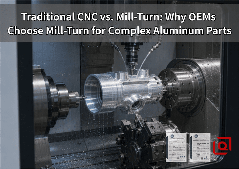
Here is a scenario every mechanical engineer and procurement lead recognizes.
Your print lands on the desk: 6061-T6 aluminum, thin walls, tight bore alignments, and radial cross-holes that intersect an internal bore. You spec a 0.012 mm runout and a positional tolerance that leaves zero room for drift.
What happens next on the floor determines whether your project succeeds or stalls.
If that part routes through a conventional multi-op setup—first turning the outer diameter on a 2-axis lathe, tossing it into a tote, moving it across the shop, and reclamping it into a custom soft-jaw fixture on a 3-axis vertical machining center (VMC)—you invite variation at every handoff.
That is where mill-turn centers change the economics.
At our facility, machining precision aluminum OEM components is not an abstract CAD exercise; it is an uncompromising physical fight against clamping distortion, chip re-cutting, thermal expansion, and stacked tolerance errors.
Here is why sophisticated OEMs have walked away from sequential CNC milling and turning setups in favor of integrated mill-turn centers—and what actually happens inside the machine enclosure to make that call pay off.
The Real Cost of the "Transfer Bottleneck"
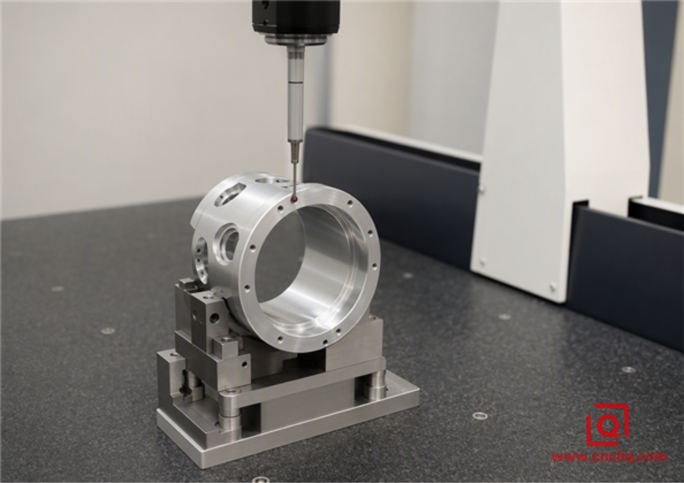
On paper, a two-machine process looks cheap. Run the turning ops on an inexpensive lathe, run the cross-drilling and pocket milling on an open bed mill. Simple, right?
Not quite.
Watch the floor for ten minutes. The operator unclamps the turned blank. Even with carefully bored 6061 soft jaws on the secondary milling fixture, chips inevitably lodge beneath the part seating face. A stray 0.03 mm chip trapped under a locating shoulder introduces an angular tilt. Tighten the hydraulic vice to 2.5 MPa, and you introduce elastic deformation into a thin-walled aluminum cylinder.
You mill the radial features, take the part out, and measure it.
The feature-to-datum true position blew past your target.
Why? Because the reference coordinate system reset the second the workpiece left the primary spindle chuck.
Conventional Routing:
Lathe Op 10 (Datum A Created)
  → Part Ejection & Queue Wait (Thermal Drop)
  → Mill Op 20 (Re-clamp on Datum A via Soft Jaws)
  → True Position Shift + Runout Degradation
In contrast, a 5-axis or multi-axis mill-turn center executes what the industry calls "Done-in-One" processing. The main spindle clamps the extruded aluminum bar stock once. The rough turning, outer profile contouring, eccentric live-tool boring, cross-hole drilling, rigid tapping, and deburring occur under a single, undisturbed coordinate system.
If the secondary side requires work, a counter-spindle synchronizes rotational speed with the main spindle, matches phase down to 0.001 degrees via C-axis encoder alignment, grabs the finished diameter, and accepts the part during automatic cutoff.
No manual operator touches. No re-clamping error. No datum migration.
Real-World Production Snapshot: The Fluid Manifold Housing
To see how this works in practice, let us examine an actual industrial fluid manifold housing we produced for a European automated testing equipment OEM.
The part design paired a precision hydraulic spool bore with four cross-milled manifold ports, angled oil galleries, and external retention threads.
Key Material & Geometry Baseline:
- Material: Aircraft-grade Aluminum 6061-T6 (AMS 4027 / ASTM B221)
- Raw Stock: 65 mm Diameter Cold-Drawn Round Bar
- Finished Length: 112.5 mm
- Critical Features:
  * 28.000 mm (+0.008 / -0.000 mm) Central Valve Bore
  * 4x Radial M12x1.5 Cross-Drilled & Threaded Ports
  * 0.010 mm Coaxiality along the full 110 mm axis
  * Ra 0.4 µm Internal Spool Surface Finish
Why the Conventional 2-Op Route Struggled
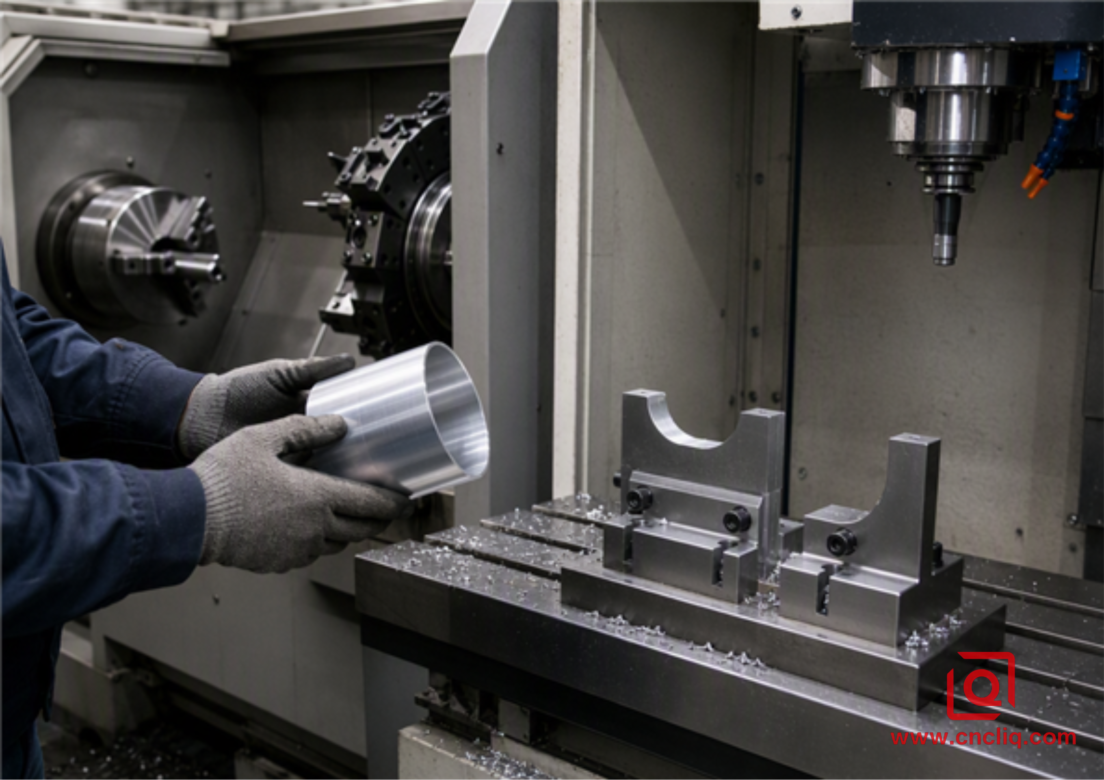
Back on the first prototype run, the customer went with a 2-step setup: turn the OD, finish it, and bore the ID on a lathe, then flip the part sideways into a standard mill vise to pop in the cross-ports.
The outcome:
-
Hydraulic Bore Ovality: Vise jaw pressure directly against that turned 4 mm wall pinched the cylinder by 0.018 mm out-of-round. The moment clamping was popped, material spring-back left an egged bore that blew right through the air-decay leak check.
-
Radial Angular Misalignment: Re-zeroing the part rotationally via an edge finder on a pre-machined flat resulted in a true position error of 0.038 mm on the cross-ports relative to the bore centerline—exceeding the 0.015 mm drawing callout.
-
Queue Time: A batch of 500 units took 14 business days to clear the shop floor due to setup changeovers and queue times between machines.
The Mill-Turn Countermeasure
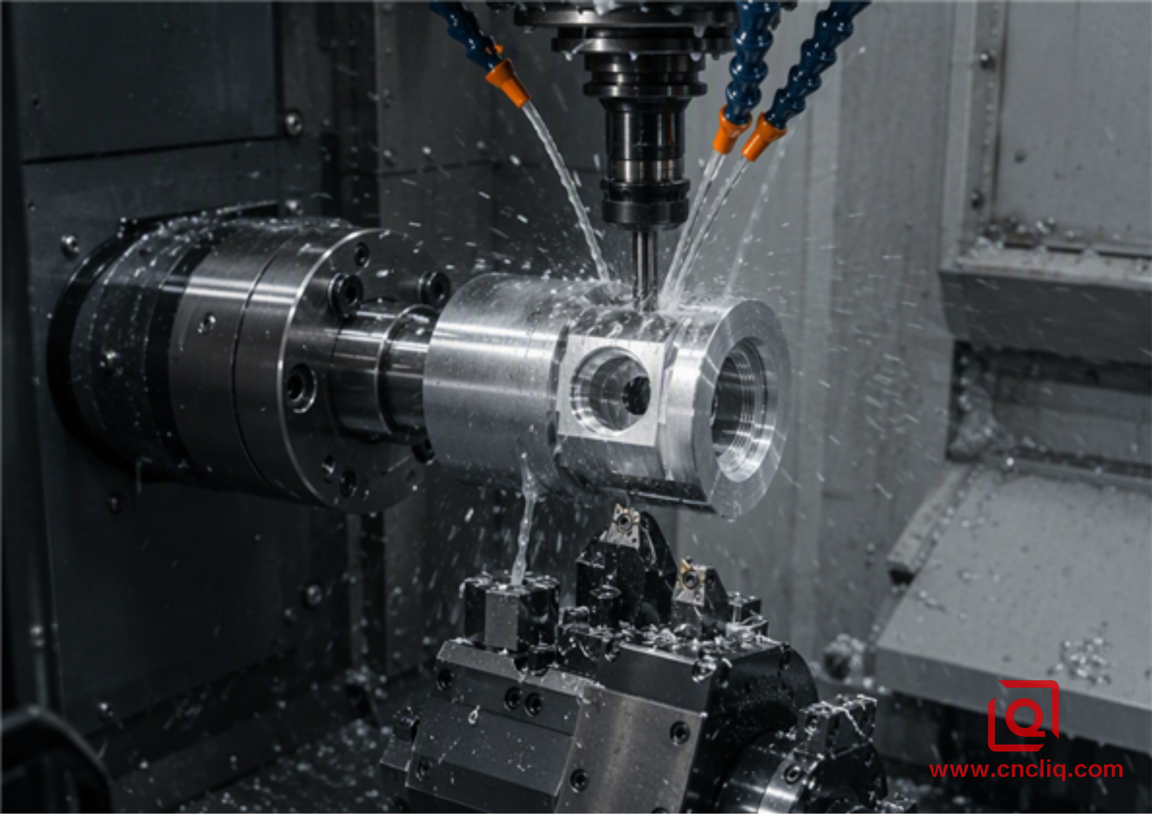
We routed the job directly to an 8-station lower turret, B-axis upper milling spindle mill-turn center.
-
Tooling & Setup:
-
Main spindle: 3-jaw collet chuck holding 65 mm stock.
-
Rough turning: Diamond CNMG 120408 carbide insert running dry with high-pressure air blast at 280 m/min cutting speed (Vc) and 0.22 mm/rev feed (fn).
-
Internal boring: Fine boring bar using polished, uncoated micro-grain carbide with a sharp 0.2 mm nose radius running at 180 m/min with synthetic water-soluble coolant (8% concentration) delivered through the tool at 70 bar to evacuate stringy aluminum chips without scratching the wall.
-
Cross-features: The main spindle clamped dynamically via C-axis disk brake holding 0.002-degree indexing rigidity. A solid carbide, 4-flute stub-length end mill milled the port relief flats, followed by drilling and form-tapping.
-
-
Secondary Operation:
-
The sub-spindle moved forward, engaged the turned front face, matched torque, clamped with smooth pie-jaws at a controlled 1.2 MPa clamping force, and parted off the workpiece.
-
The sub-spindle completed the rear face facing, counterboring, and deburring.
-
The results speak for themselves:
| Processing Parameter | Conventional 2-Op (Lathe + VMC) | Integrated Mill-Turn Center |
| Total Setups / Clamping Ops | 2 distinct setups (Op 10 + Op 20) | 1 single setup (Sub-spindle transfer) |
| Total Floor Cycle Time | 18.5 min machining + 3 days queue | 6.8 min complete single-cycle drop |
| Bore Roundness Deviation | 0.014 mm to 0.022 mm (Distorted) | 0.003 mm to 0.005 mm (Consistent) |
| Cross-Hole True Position | 0.035 mm (Accumulated fixture error) | 0.008 mm (Direct C/Y-axis positioning) |
| Final Part Rejection Rate | 6.4% across a 500-pc pilot run | 0.2% across a 2,000-pc production run |
| Applicable Standards | ISO 2768-m, ASTM B221 | ISO 2768-f, ISO 1101, ASME Y14.5 |
Machine Kinematics: Why the Mechanics Matter for Aluminum
Why does a mill-turn machine handle aluminum alloys (such as 6061, 7075-T651, and 2024) with markedly higher structural integrity than standalone mills or lathes?
It comes down to rigidity, thermal stability, and axis synchronization.
                  +----------------------------------+
                  |    B-Axis Milling Spindle        |
                  |  (12,000 RPM, Multi-Angle Mill)  |
                  +-----------------+----------------+
                                    |
                                    v
   +-------------------+    [Workpiece]    +--------------------+
   |   Main Spindle    | ===[ 6061-T6  ]===|    Sub-Spindle     |
   | (C-Axis / 0.001°) |                   | (Opposed Coaxial)  |
   +-------------------+                   +--------------------+
                                    ^
                                    |
                  +-----------------+----------------+
                  |       Lower Tool Turret          |
                  |     (Static & Driven Tools)      |
                  +----------------------------------+
1. Managing Thermal Expansion (ΔL = L × α × ΔT)
Aluminum moves a lot with heat—thermal expansion sits around 23 × 10⁻⁶ / K. Rip 40% of the blank away on a roughing pass, and you will watch the part's core spike from 20 °C straight up to 55 °C before you know it.
In a traditional shop routing, that hot part cools off in a plastic bin overnight, shrinking measurably before an operator loads it into a milling fixture the next morning. Your datum surfaces are already moving targets.
Running this on a mill-turn lets flood coolant—or high-pressure through-spindle coolant—lock the part's temperature dead flat. You rough, you semi-finish, let it soak through a timed 30-second dwell or intermediate rinse, then skin the final pass without the job ever leaving that same thermal pocket.
2. Radial Y-Axis Interpolation vs. True Orthogonal Movement
Older live-tool lathes often had no real Y-axis to speak of; they just cheated cross-travel by syncing the X slide with the C-axis spindle. That trick handles sloppy tolerances fine. Try holding 0.01 mm perpendicularity on a flat or an O-ring face groove, though, and tool push-off will crown the feature every single time.
Modern mill-turn centers employ true orthogonal Y-axis mechanical ways. The milling head travels cleanly along a dedicated structural guide rail perpendicular to the turning axis.
In plain terms, slotting out a pocket or dropping in an O-ring groove leaves the floor dead flat, while side walls square up cleanly against your ASME Y14.5 callout.
Controlling Chips and Cutters in High-Speed Aluminum Machining
Aluminum is soft compared to stainless steel or Inconel, but it presents its own distinct workshop headaches: built-up edge (BUE), work hardening under dull tools, and bird-nesting chips that wrap around the chuck.
Here is how we set up the cutting parameters inside our mill-turn programs to maintain mirror finishes and tight dimensions:
-
Surface Speeds for 6061-T6:
Turning roughing passes: 250 to 320 m/min.
Turning finishing passes: 350 to 450 m/min with a 0.08 mm/rev feed rate to hit Ra 0.8 µm directly off the insert without secondary polishing.
Live tooling milling (Solid Carbide End Mills): 300 to 500 m/min cutting speed, spindle speeds pushed to 10,000–14,000 RPM, chip load targeted at 0.06 to 0.12 mm per tooth depending on tool stick-out.
-
Tool Coatings:
Never use generic AlTiN or TiAlN-coated tooling for aluminum. The aluminum affinity to aluminum-based coatings causes rapid material welding and micro-welding at the cutting edge. Instead, we run polished uncoated carbide (PCD for ultra-long runs) or specialized DLC (Diamond-Like Carbon) coatings with extremely low friction coefficients (under 0.1).
-
Chip Breaking Tactics:
Mill-turn programming uses oscillatory cutting (chip-breaking macros) during rough turning. By momentarily oscillating the feed axis out of the cut for a millisecond, the machine snaps ductile aluminum chips into small, manageable curls rather than allowing them to wrap into dangerous birds' nests that scratch precision surfaces or jam tool turrets.
Key DFM Guidelines for Your Next Mill-Turn Aluminum Component
If you want to maximize the efficiency of mill-turn machining and lower your per-unit costs, structure your CAD model with these shop-floor realities in mind:
-
Leverage Standard Collet Diameters:
Design the largest outer diameter of your part to match standard raw bar stock sizes (e.g., 20 mm, 25 mm, 32 mm, 50 mm). This allows bar-fed, automated production without requiring prior centerless grinding or custom turning of the raw stock.
-
Avoid Uniform Deep Internal Radices at the Base:
When designing pockets on cylindrical bodies, leave internal corner radii of at least 1.5 to 2.0 mm. This allows a standard 3 mm or 4 mm solid carbide end mill to blend the corner without squealing or inducing chatter at high RPM.
-
Align Cross-Holes with Coordinate Planes:
Whenever you can, drop cross-holes dead square to the centerline or pin them strictly to common radial indexing angles. Modern articulating heads offer plenty of reach, sure, but sticking to standard planes still trims cut times and spares you from programming nightmarish multi-axis touch-probe inspection routines.
-
Account for Secondary Anodizing Tolerances:
Remember that MIL-A-8625 Type II sulfuric anodizing typically adds 5 to 12 µm per surface (10 to 24 µm to an internal bore diameter), whereas Type III Hardcoat anodizing deposits 25 to 50 µm per surface. On a mill-turn program, we bias our finish-bore tool offsets to the low end of the tolerance band to leave precise breathing room for post-anodizing buildup.
The Bottom Line: Total Cost of Ownership
Looking strictly at machine hourly rates misses the bigger picture.
Yes, a multi-axis mill-turn center carries a higher hourly machine rate than a standard 3-axis CNC vertical mill.
However, when you factor in:
-
Zero secondary custom fixture tooling costs (saving $1,500 to $4,000 in dedicated soft-jaw development per SKU),
-
Up to 60% reduction in total cycle and transit time,
-
Sub-0.5% scrap rates on high-value parts, and
-
Guaranteed runout and coaxiality across multiple datums,
...the total landing cost per qualified piece drops substantially.
If your aluminum components demand tight coaxiality between turned diameters and milled features, consider skipping the multi-machine relay. Mill-turn manufacturing provides an unbroken path from raw extruded bar to finished, CMM-verified hardware ready for the assembly line.
FAQs
Q1: What batch sizes are cost-effective for mill-turn aluminum parts compared to 3-axis CNC?
A: Dialing in a mill-turn hurts on the front end—bank on 3 to 5 hours just burning through CAM simulation and setting offsets. For multi-op jobs needing dedicated jigs, batch economies typically kick in around 50 to 100 parts. Still, even on 10 to 30 piece short runs, one-and-done machining pays off the second your true position or runout dips under 0.012 mm, since you completely dodge sinking 1,500+ into OP2 milling fixtures.
Q2: Can mill-turn centers handle harder aluminum alloys like 7075-T651 as easily as 6061?
A: Yes, and in many ways, 7075-T651 is actually easier to manage inside a mill-turn enclosure than 6061. Its higher zinc content and yield strength produce short, crisp chips that break cleanly during high-speed turning and thread-milling, virtually eliminating chip bird-nesting. The main adjustment on our end is reducing surface speeds by roughly 15–20% and switching to high-shear, micro-grain carbide tooling to prevent premature edge chipping under aggressive milling engagement.
Q3: How do you verify critical dimensions on parts with interrupted cuts and intersecting cross-bores?
A: We use a dual-layer verification protocol. First, an on-machine optical touch probe (such as Renishaw OMP40-2) verifies datum positions, bore diameters, and axial distances before the part is parted off by the sub-spindle. Once parted off, pieces run through a full 100% first-piece buyoff plus continuous SPC in our climate-held quality room (20 °C ± 0.5 °C). We probe them on a CMM and track cylindrical features using optical shaft scanners, all dialed in to ISO 10360 calibration standards.
Q4: How do mill-turn centers prevent thin-walled aluminum cylinders from crushing during sub-spindle transfer?
A: Clamping force management is critical. We use programmable hydraulic/pneumatic proportional valves on the sub-spindle chuck, lowering clamping pressure to 0.8–1.2 MPa depending on wall thickness. Fixture-wise, we bore custom 360-degree full-contact pie jaws matched dead-on to the turned OD, ditching standard serrated 3-jaw teeth. Wrapping the whole circumference spreads chuck pressure flat across the skin, killing off point pinching before it can egg the bore or kick out runout.
Q5: Which file types and drawings give you everything needed to quote a mill-turn job right on the money?
A: Best bet is to send over a 3D model—preferably STEP AP214 or AP242, since those hold onto embedded GD&T—paired with a clean 2D PDF print. Make sure your 2D print nails down your primary datums (A, B, C), tight limits, targeted Ra finishes, and exact surface calls like MIL-A-8625 Type II anodize or Type III Hardcoat. That way, we can figure our tool passes and baking-in plating growth from day 1.
Summary
Bouncing tricky aluminum parts between standalone lathes and mills stacks up setup errors, crushes thin walls under repeat clamping, and bogs jobs down waiting for the next spindle. Packing multi-axis turning, synchronized C/Y/B live cutting, and automated sub-spindle handoffs into 1 continuous grab stops datum drift cold. Backed by solid chip evacuation, true orthogonal travel, and stable temperature soak, this one-and-done workflow trims run times by up to 60%, nails true position under 0.010 mm, and cuts piece-part cost on tight-tolerance OEM runs.
Contact Information
Disclaimer
All technical articles, material specifications, machining recommendations, and surface treatment details published on this blog are for informational and reference purposes only. Please note that general blog insights do not replace signed technical agreements. Because custom parts vary by material heat numbers, machine calibrations, and specific tolerances, binding quality specs are governed solely by your approved CAD drawings, signed contracts, and formal quality plans.
All customer case studies featured on this blog have been thoroughly anonymized and sanitized. The performance metrics, manufacturing workflows, and imagery displayed serve solely to demonstrate our custom machining capabilities and do not represent a single universal standard for all orders.
Liqin Manufacturing Team
Built on 18 years of precision engineering experience, Ningbo Liqin Industry manufactures high-tolerance metal components for demanding global markets. We operate out of a 6,500 m² production hub equipped with over 150 machines, running 4-axis and 5-axis CNC machining, mill-turn machining, cold extrusion, and pressure die casting under one roof. This setup allows us to manage projects seamlessly, taking parts from initial CAD concepts directly to finalized shipments.
We handle quality control with zero compromise. We treat tight tolerances with the engineering discipline they require. Backed by ISO 9001, ISO 13485, and IATF 16949 certifications, our QA engineers run strict IPQC, FQC, and OQC checks on every single production batch. From CMM dimensional mapping and optical profiling to hardness and salt-spray testing, we validate your critical specs upfront—so you receive drop-in ready components with zero assembly headaches or costly line stoppages. On top of manufacturing, you can rely on us for two-hour response times on new RFQs, direct support for prototype sampling, and smooth export shipping across Europe, North America, Asia, and Oceania.
Welcome your inquiries and samples. Visit our website or contact us directly for a competitive quote!
