 English




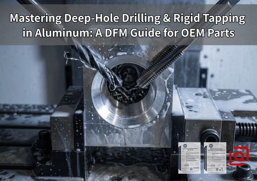
Every design engineer knows aluminum cuts easily. Feed a basic carbide mill into 6061-T6, push the travel rate, and clean chips fly off without a hitch. That easy predictability vanishes the second a print demands drilling a 3.20 mm oil passage 45 mm deep inside a pocket, bottoming right out into an M4 blind hole with extra-long full thread reach.
Suddenly, an alloy celebrated for its machinability starts acting gummy and unforgiving. Fine chips pack tight into tool flutes, cutting fluid turns to vapor inside the pocket, friction swells the hole wall inward against the tool shank, and an expensive custom manifold block ends up ruined directly on the machine fixture.
Deep micro-drilling and rigid tapping in wrought aluminum alloys are notorious failure points in precision OEM production. Once hole depth extends past five to ten times diameter, standard chip evacuation physics breakdown completely. Metal removal becomes secondary to thermal management and continuous chip flushing.
Understanding how aluminum behaves under high depth-to-diameter conditions helps design engineers eliminate shop floor friction, reduce scrap, and streamline manufacturing before drawings ever hit the production line.
1. The Real Mechanics of Deep Aluminum Holes
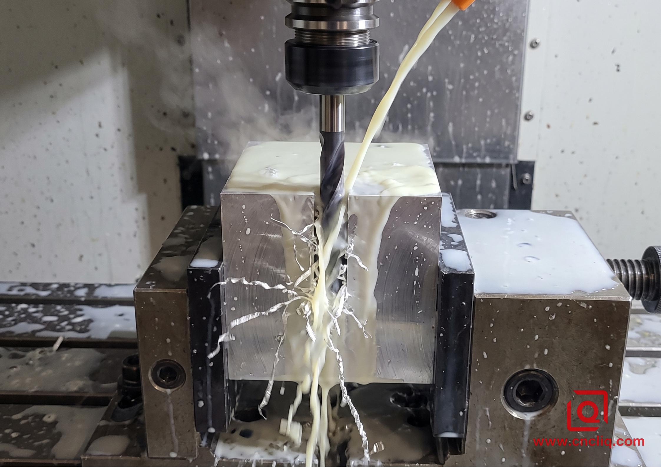
In custom machine shops, any hole deeper than five times its diameter shifts the operational approach. Once you venture beyond ten times diameter, you enter territory where tool deflection, heat buildup, and chip packing compound into severe tool drift.
Aluminum is an excellent thermal conductor, but its high coefficient of thermal expansion creates unexpected traps during deep drilling. As the tool edge continuously works against the bottom of a deep channel, intense friction generates localized thermal energy faster than the surrounding mass can dissipate it.
-
Bore Wall Pinching: The surrounding metal expands inward around the drill body. If the tool hesitates or feed rates drop during the cut, the margins seize against the bore wall almost instantaneously, welding the carbide straight to the workpiece.
-
Stringy Chip Wedging: Cast metals break into predictable, granular chips, but ductile wrought alloys like 6061 and 5052 generate long, ductile ribbons. In a deep hole without direct escape paths, these ribbons fold over themselves, score the internal finish, and act as a physical dam blocking incoming cutting fluid.
Entry Faces and Centerline Wander
One persistent issue on incoming custom prints is demanding tight positional true position on an extended deep hole while allowing the drill to start on a raw, uneven, or slanted casting face. A drill tip touching an angled surface deflects instantly. Once a flexible small-diameter drill wanders off-axis during the first few millimeters of engagement, no machine spindle rigidity can pull that hole back to its true geometric centerline.
Shop Floor Practice: Always design a flat entry pocket or planar landing perpendicular to the drill axis. In production, we run a short, rigid spotting drill with an included angle designed to match the secondary deep drill tip. This ensures the drill self-centers smoothly into a guided indentation, keeping radial runout to a minimum from the very first revolution.
2. Chip Evacuation: Fluid Dynamics Over Raw Horsepower
When hole depth forces chips to travel several inches against gravity and centrifugal force, standard twist geometry is simply the wrong tool for the job.
Parabolic Flute Geometry
Standard twist drills feature narrow flutes suited for quick, shallow clearance. For deep OEM aluminum components, custom parabolic flute profiles are critical. These designs widen the flute valley, opening up significantly more cross-sectional volume so stringy aluminum chips slide freely upward without packing tightly against the bored wall.
The Reality of High-Pressure Internal Coolant
Flooding cutting fluid through external machine nozzles is ineffective past three times diameter. The high-velocity spinning action of the tool shank combined with hot rising gases forms an impenetrable vapor barrier around the hole entrance, blowing external coolant straight off the opening.
To overcome this:
-
High-Pressure Fluid Columns: We drive specialized high-pressure delivery systems pumping synthetic fluid directly through internal coolant passages inside the drill body at 70 bar. This pressurized jet shoots directly out of the drill face, hydro-dynamically forcing chips backward through the flutes like a piston ejecting waste.
-
Emulsion Concentration Adjustments: While everyday facing and slotting runs smoothly at standard water-to-oil concentrations, deep boring and micro-tapping require richer fluid mixtures. Elevating lubricant concentration provides the extreme-pressure film strength needed to stop soft aluminum from sticking to cutting edges under continuous contact.
3. Tapping Dynamics: Cutting Threads vs. Forming Threads
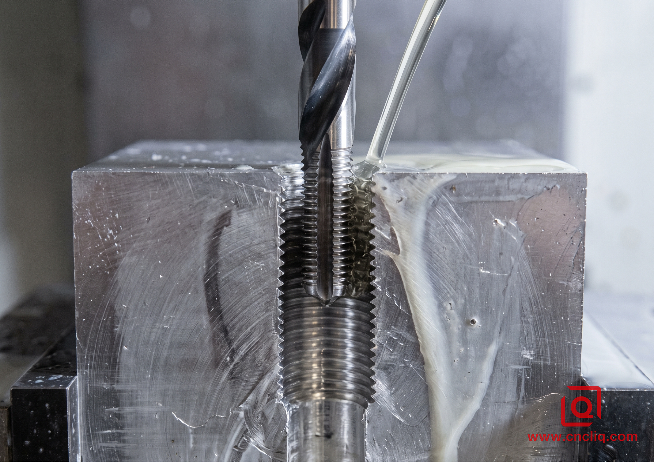
Tapping deep blind holes in aluminum is where parts are most vulnerable. Snapping a small tap at the bottom of a near-finished block scraps the piece entirely, wasting hours of upfront roughing and fine surface profiling. Choosing between cutting and forming threads determines whether a design is truly production-ready.
Why Cold Forming Wins in Ductile Alloys
Whenever an OEM drawing allows flexibility, we advocate converting internal blind threads in ductile alloys like 6061-T6 from traditional cutting taps to roll forming taps.
-
Zero Swarf Generation: Cutting taps cut metal, throwing continuous, razor-sharp chips into the hole bottom where they quickly bundle and bind the tool flutes. Form taps work by displacement; they displace the aluminum plastically to roll the profile without shaving away a single grain of material.
-
Superior Thread Grain Structure: Because cold forming works with the natural grain boundaries rather than severing them, the root and crest of cold-rolled threads demonstrate markedly higher resistance against stripped threads and bolt pull-out.
-
Exceptional Batch Consistency: Forming tools have no cutting edges to wear down or dull, meaning pitch diameters remain uniform across extended production runs.
The Pre-Drill Hole Sizing Mismatch
Design engineers must note: A roll form tap requires a substantially larger pre-drilled pilot hole than a cutting tap.
-
A standard M6x1.0 cut thread relies on a 5.00 mm drilled pilot hole.
-
An equivalent M6x1.0 roll form thread requires a 5.55 mm pre-drilled pilot hole.
When engineering drawings specify a standard pilot hole diameter alongside a callout for roll-formed threading, the incoming forming tool faces massive material overfill, causing extreme torque spikes that shear the tap before it reaches depth.
4. Rigid Tapping Synchronization and Hole-Bottom Clearance
Modern CNC machines utilize rigid tapping, using digital encoder feedback to lock spindle rotation and vertical feed into exact alignment without floating tap holders. However, machines must still physically brake, stop, and reverse at the bottom of a hole.
At the deepest point of an internal thread:
-
The spindle must decelerate to a dead stop from high rotational speeds within a fraction of a thread lead.
-
During rapid tapping, rotational mass and motor deceleration profiles create tiny mechanical overshoots past programmed depths.
-
The Design Rule: Never design usable thread length that bottoms out flush against the drilled hole depth. Always build a safety cushion equal to at least 3 full thread pitches between the end of the bolt engagement zone and the conical tip of the pre-drilled pocket.
5. Quick DFM Reference: Hole and Thread Guidelines
The table below outlines real-world engineering baselines derived from custom CNC setups running 6061-T6 and 7075-T651 stock:
| Engineering Parameter | Standard Baseline | Deep-Hole / Fine Feature Range | Extreme Tooling Envelope | Applicable Standards |
| Depth-to-Diameter Ratio | 1 to 5 times diameter | 6 to 15 times diameter | 16 to 30 times diameter | DIN 6537 / ISO 5419 |
| Internal Hole Runout | 0.02 mm per 25 mm depth | 0.05 mm per 50 mm depth | 0.12 mm per 100 mm depth | ISO 286 / ASME Y14.5 |
| Coolant Delivery Setup | External flood delivery | Through-spindle at 30 to 70 bar | Ultra-high pressure through-spindle | Proprietary OEM specs |
| Drill Tip Geometry | 118 degree standard | 135 to 140 degree solid carbide | 140 degree with parabolic profile | DIN 1412 Form E |
| Usable Thread Depth Ratio | 1.0 to 1.5 times diameter | 1.5 to 2.0 times diameter | 2.5 times diameter maximum | ASME B1.1 / ISO 965-1 |
| Blind Hole Bottom Relief | 2 full thread pitches | 3 to 4 full thread pitches | 5 full thread pitches | ANSI B94.9 |
| Thread Profile Engagement | 65 percent | 70 to 75 percent (forming) | 80 percent maximum limit | Machinery Handbook |
6. Application Analysis: Complex Fluid Manifold Blocks
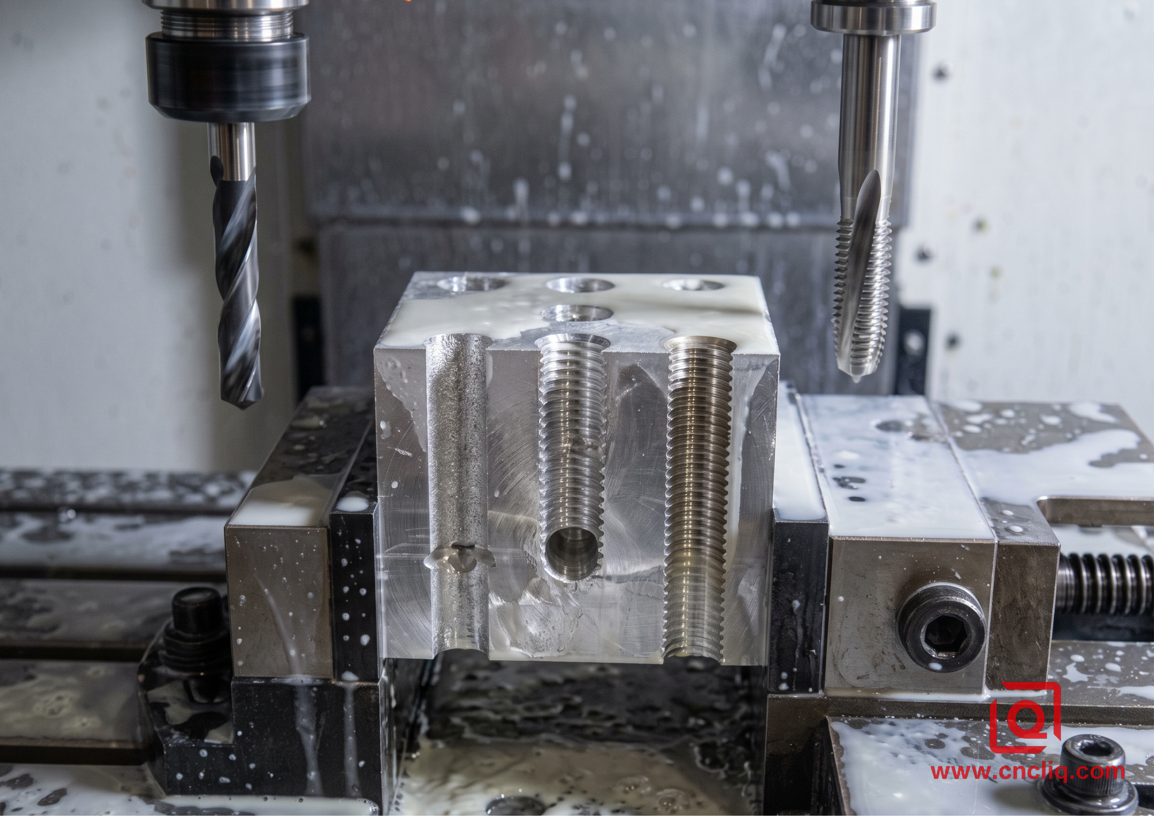
A client in the industrial instrumentation space approached us with a high-performance 6061-T6 manifold block housing several internal pneumatic pathways.
Initial Design Hurdles
The original print featured narrow internal passages measuring 2.80 mm in diameter, drilled straight to a depth of 38.00 mm. The design placed these holes directly into blind M3x0.5 threaded connection ports.
The client's previous machining sources faced catastrophic failure rates:
-
Tiny spiral-flute taps repeatedly fractured inside the channels due to chip compaction.
-
Drill wander caused internal passages to break through adjacent wall sections.
-
High pressure hydraulic testing at 210 bar frequently washed loose cutting burrs into sensitive downstream valves.
Original Customer Print:
[ Planar Face ] -> [ 2.80 mm Bore x 38.00 mm Depth ] -> [ M3x0.5 Cut Thread x 9.00 mm Depth ] -> [ 1.00 mm Clearance ]

DFM Optimized Approach:
[ Planar Face ] -> [ Spot Pocket + 90 Deg Chamfer ] -> [ 2.85 mm Parabolic Drill ] -> [ M3 Form Tap x 6.00 mm Depth ] -> [ 3.50 mm Clearance ]
The DFM Solution Applied
-
Thread Depth Rationalization: The original drawing demanded a full 9.00 mm of usable thread on an M3 fastener. Engineering shear stress calculations confirmed that in 6061 aluminum, thread engagement beyond 6.00 mm provides zero additional joint retention; the steel fastener itself will yield and snap before the aluminum threads pull out. The customer agreed to shorten the thread depth.
-
Converting to Chipless Cold Forming: We eliminated cutting taps in favor of specialized cold forming taps coated in titanium diboride, a slick surface treatment that prevents soft aluminum from welding to the tool. Pre-drilled pilot holes were enlarged to 2.78 mm to hit a secure thread height profile without stressing the tool.
-
Advanced Micro-Step Drilling Strategy: Instead of standard retract-peck routines that pull chips back into the hole, we utilized solid-carbide parabolic drills backed by 70 bar of through-spindle coolant. Micro-dwell motions fractured the aluminum into tiny flakes that were flushed out continuously by the coolant stream.
Operational Results
The updated part design completely eliminated scrap across the entire production order of 850 components. Internal bore runout across the full 38.00 mm depth dropped to under 0.018 mm, and cycle times dropped by 27 percent per block, yielding measurable component cost reductions.
7. DFM Checklist for Aluminum Holes and Threads
Before sending native CAD files and engineering prints out for quote, run through this manufacturing validation checklist:
-
[ ] Keep Depth-to-Diameter Ratios Manageable: Design hole depths under 8 times diameter whenever practical. If deeper channels are critical, maintain generous wall thickness around the passage to resist internal fluid pressure.
-
[ ] Limit Blind Thread Depths: Restrict full thread engagement to 1.5 to 2.0 times nominal bolt diameter. Extra depth adds tool breakage risk with negligible mechanical gain.
-
[ ] Allow Spindle Deceleration Relief: Ensure the distance between the end of usable thread and the drill point equals at least 3 full thread pitches to cushion CNC spindle deceleration.
-
[ ] Check Pilot Holes for Forming Taps: If your design benefits from chipless roll forming, verify pilot hole callouts reflect cold forming standards rather than outdated cutting tap charts.
-
[ ] Provide Flat Entry Surfaces: Ensure deep-drilled holes enter perpendicular to the surface, or design a flat milled counterbore to prevent drill wander.
Successful precision machining in aluminum relies on smart design planning. Aligning your CAD geometry with the realities of chip clearance, thermal movement, and machine synchronization delivers tighter part tolerances, cleaner threads, and dependable production economics across every production run.
FAQs
Q1: Why do taps snap so easily in aluminum when it is considered a soft metal?
Softness in aluminum tricks people. Unlike cast stock that shears into dust, ductile grades heat up fast, stretch, and turn into glue. Trapped in a blind pocket, stringy chips pack tightly around the flutes and bind the tool. Worse, intense local heat welds the metal straight onto the cutting lips. The second that built-up edge grabs, torque spikes in less than half a revolution, shearing small taps before the servo drive even senses the load.
Q2: What is the main operational difference between cut tapping and form tapping?
Cut taps rely on sharp flutes to slice material away, dumping continuous curly swarf that must crawl upward to clear the hole. Form taps remove zero material. Instead, engineered lobes cold-roll and flow the metal into pitch profile. With zero swarf generated, you rule out blind-hole clogging entirely, leaving a work-hardened, mirror-burnished flank that holds up far better against stripping.
Q3: How do you keep long, slender drills from wandering off-target?
Runout almost always traces back to initial touch-off. When a skinny drill meets rough stock or a slight draft angle, the chisel tip skids sideways, steering the entire hole off-axis. The fix is spot-facing a flat landing pad, then dropping in a stubby, rigid center drill to prep a conical dimple. That recess seats the point of the long drill, locking it on center so it tracks straight down the bore.
Q4: Why does flood coolant fail on deep bores, and what works better?
Once a drill buries itself deep in a hole, high rotational speeds paired with rising heat whip up a vapor cushion. Fluid from generic external nozzles splashes against that barrier and never reaches the bottom, leaving the lips bone-dry. High-pressure through-spindle coolant fixes this by routing fluid straight through micro-ports inside the drill shank. The stream blasts out right at the shear zone, knocking down heat and blowing chips back up the flutes.
Q5: If deep threads do not make an aluminum bolt connection stronger, what actually happens?
In soft aluminum, the first three to five engaged pitches carry virtually the entire clamp load. Chasing deeper threads past that point sheds practically zero extra stress into the joint. Push the assembly past its limit, and the steel bolt snaps clean off before the internal threads pull out. All that extra thread engagement really delivers is wasted friction, thermal buildup, and a high risk of scrapping a finished part over an embedded broken tap.
Summary
Boring deep oil paths and tapping blind threads in aluminum never comes down to brute force—it hinges on controlling thermal growth, swarf evacuation, and tool kinematics. When product teams hold depth ratios to sane boundaries, draft flat lead-ins, swap over to chipless roll-form taps, and leave adequate clearance under blind threads, tool blowouts and wander dry up. Factoring cutting mechanics into CAD models before releasing prints turns headache-inducing aluminum OEM parts into stable, repeatable machining runs.
Contact Information
Disclaimer
All technical articles, material specifications, machining recommendations, and surface treatment details published on this blog are for informational and reference purposes only. Please note that general blog insights do not replace signed technical agreements. Because custom parts vary by material heat numbers, machine calibrations, and specific tolerances, binding quality specs are governed solely by your approved CAD drawings, signed contracts, and formal quality plans.
All customer case studies featured on this blog have been thoroughly anonymized and sanitized. The performance metrics, manufacturing workflows, and imagery displayed serve solely to demonstrate our custom machining capabilities and do not represent a single universal standard for all orders.
Liqin Manufacturing Team
Built on 18 years of precision engineering experience, Ningbo Liqin Industry manufactures high-tolerance metal components for demanding global markets. We operate out of a 6,500 m² production hub equipped with over 150 machines, running 4-axis and 5-axis CNC machining, mill-turn machining, cold extrusion, and pressure die casting under one roof. This setup allows us to manage projects seamlessly, taking parts from initial CAD concepts directly to finalized shipments.
We handle quality control with zero compromise. We treat tight tolerances with the engineering discipline they require. Backed by ISO 9001, ISO 13485, and IATF 16949 certifications, our QA engineers run strict IPQC, FQC, and OQC checks on every single production batch. From CMM dimensional mapping and optical profiling to hardness and salt-spray testing, we validate your critical specs upfront—so you receive drop-in ready components with zero assembly headaches or costly line stoppages. On top of manufacturing, you can rely on us for two-hour response times on new RFQs, direct support for prototype sampling, and smooth export shipping across Europe, North America, Asia, and Oceania.
Welcome your inquiries and samples. Visit our website or contact us directly for a competitive quote!
