 English




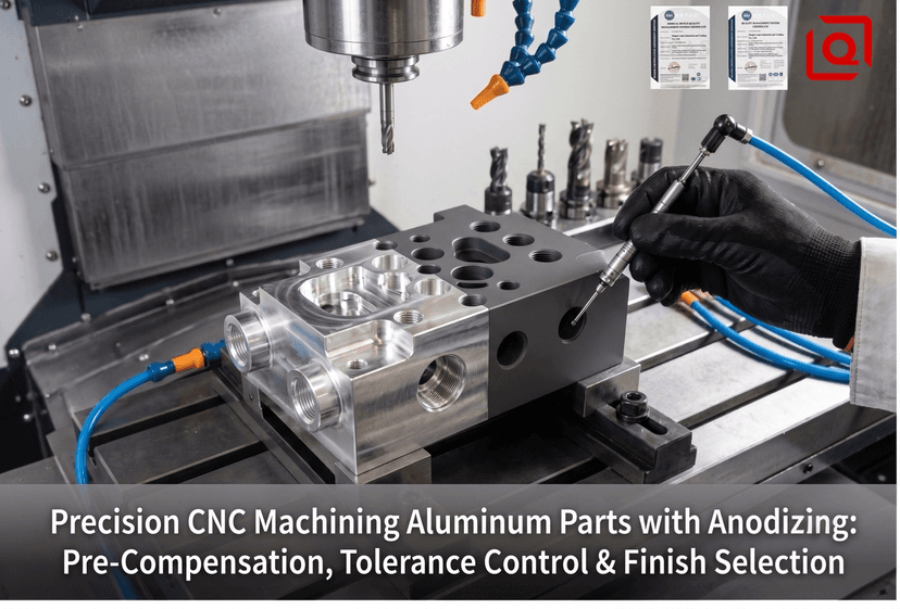
If your shop floor keeps milling 6061-T6 aluminum to ±0.005 mm final blueprint tolerances before sending parts out to Type III Hardcoat Anodizing, you're lighting profit margin on fire. Anodizing isn't paint. It grows into and out of the substrate simultaneously. Stop blaming your plating vendor for seized thread pitch diameters and out-of-round H7 bearing bores—start compensating your toolpaths upstream in CAM.
The Pre-Compensation Audit: Stop Blaming the Plating Tank
[Raw Stock: AL6061-T651] ➔ [Rough End Mill: 12mm 3-Flute Carbide @ 12,000 RPM]
  ➔ [Finish Bore: Offset -0.0125mm per side] ➔ [Type III Hardcoat (Mil-A-8625)]
  ➔ [25µm Penetration / 25µm Growth] ➔ [Final Target Fit: H7 Tolerance Pass]
Here is the hard math every CAM programmer forgets: Type III Hardcoat Anodizing per MIL-A-8625 Type III Class 1 adds measurable dimensional change. For a total target oxide layer thickness of 50 µm (0.002”), exactly 50% (25 µm / 0.001”) penetrates the aluminum matrix, and 50% (25 µm / 0.001”) builds up on the exterior surface.
Dimensional Impact Reference Matrix
| Feature Geometry | Anodize Specification | Total Film Thickness | Dimensional Change (Per Surface) | CAM Offset Strategy |
| External OD / Boss | MIL-A-8625 Type II (Clear) | 12 µm | +6 µm (+0.00024”) | Machine undersize by 12 µm on Diameter |
| Internal Bore (H7) | MIL-A-8625 Type II (Clear) | 12 µm | -6 µm (-0.00024”) | Machine oversize by 12 µm on Diameter |
| External OD / Boss | MIL-A-8625 Type III (Hardcoat) | 50 µm | +25 µm (+0.0010”) | Machine undersize by 50 µm on Diameter |
| Internal Bore (H7) | MIL-A-8625 Type III (Hardcoat) | 50 µm | -25 µm (-0.0010”) | Machine oversize by 50 µm on Diameter |
| M6x1.0 Tapped Hole | MIL-A-8625 Type III (Hardcoat) | 50 µm | Pitch Dia Shrinks ~100 µm | Use GH5/GH7 Oversize Taps prior to anodize |
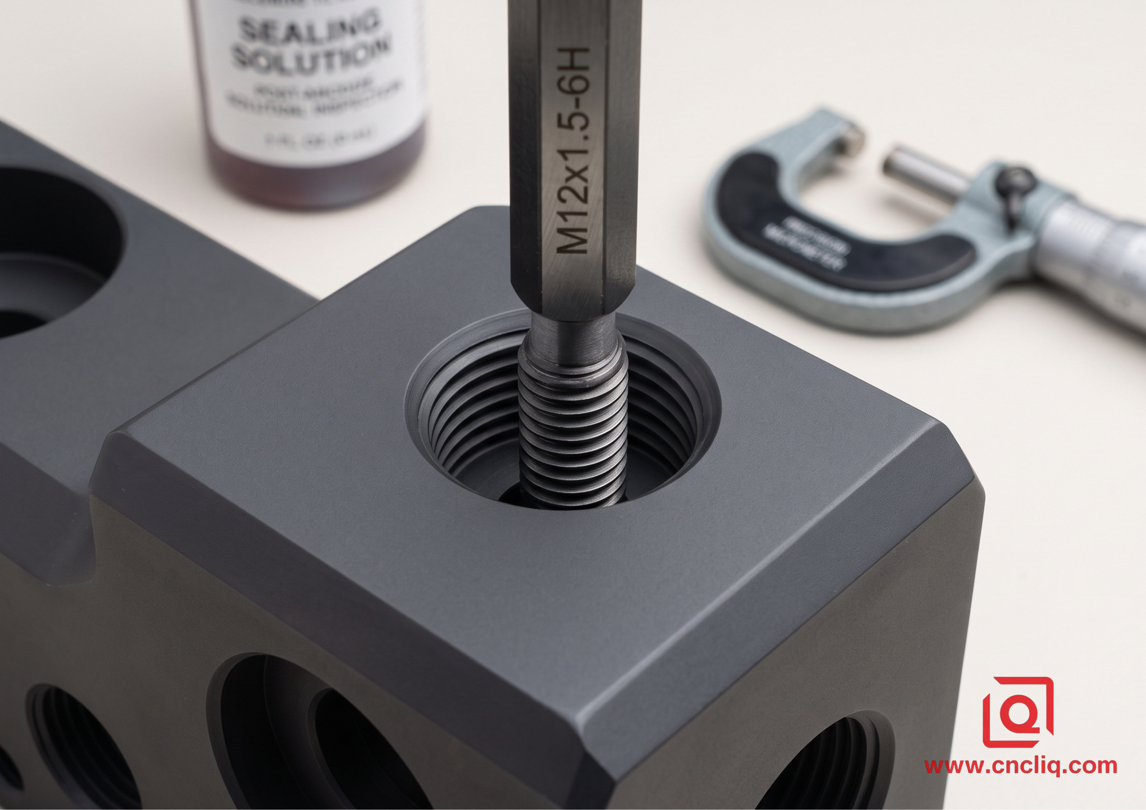
When boring an ISO H7 housing for a 6204-RS bearing (20.000 mm +0.021/-0.000 mm), machining to 20.010 mm pre-plate means that after 50 µm Type III coating, your finished bore collapses to 19.960 mm. The bearing won't press—it galling-seizes at 3 kN load.
The Fix: Program your finish bore cycle using a 16 mm solid carbide fine-boring head with a target pre-anodize diameter of 20.060 mm ±0.004 mm. As the 25 µm per-side dielectric oxide layer grows, the bore pulled back down precisely to 20.010 mm, right in the sweet spot of H7.
Shop-Floor Diagnostic Case Study: The Seized Pneumatic Manifold
-
Part Geometry: 7075-T651 Aircraft Aluminum Hyd-Pneumatic Block with 6x M12x1.5-6H internal port threads and dual Ø12.00 mm slide-valve channels.
-
Failure Mode: Post-anodize leak testing showed 1.8 bar pressure drop within 15 seconds. Slide valves jammed during assembly; M12 threads stripped at 22 Nm torque (spec: 45 Nm).
-
Root Cause Investigation:
-
The machinist used a standard 6H thread tap. Post-Hardcoat oxide growth choked the thread pitch diameter by ~0.088 mm, turning 6H fit into an interference condition. The operator forced bolts with an impact wrench, shearing the brittle 60 HRC Al₂O₃ skin.
-
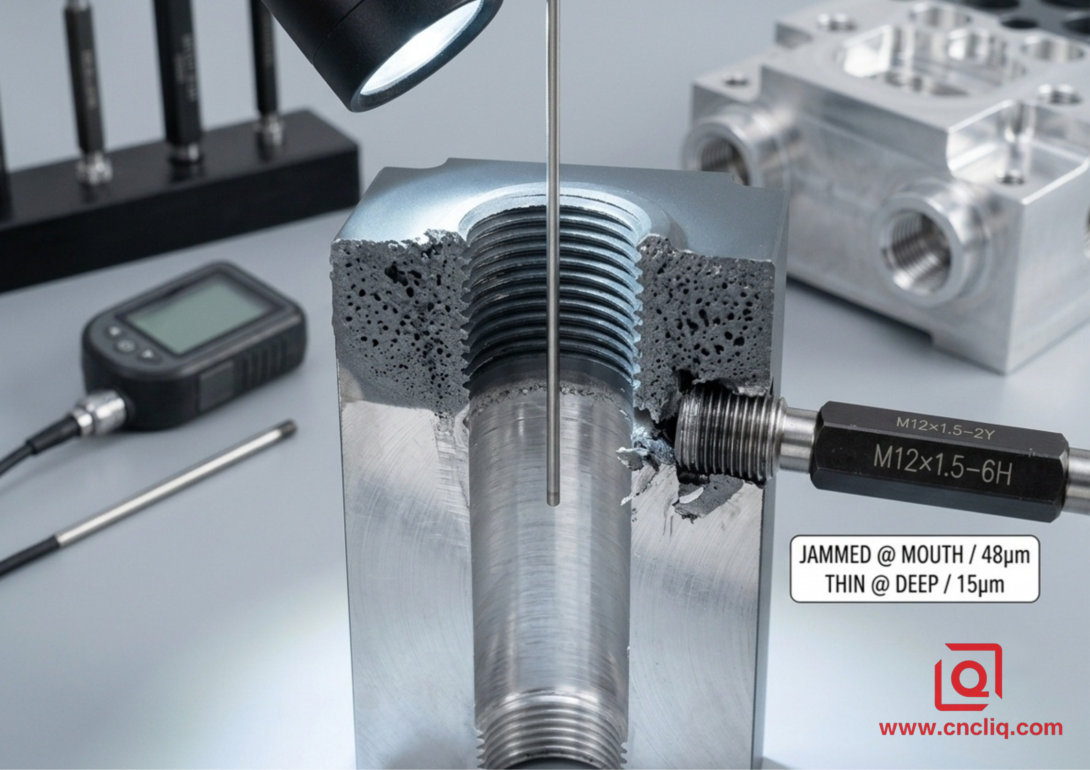
The valve bore was reamed with a standard 12.00 mm H7 reamer. Post-plate thickness varied from 42 µm at the mouth to 18 µm deep inside the 80 mm blind channel due to localized current density dropping off inside high-aspect-ratio cavities (Aspect Ratio > 6:1).
-
   POOR CATHODE / ANODE FLOW IN BLIND HOLE
   [Tanks Current] ──> [Outer Edge: 48µm Oxide]  (Choked Opening)
                       [Deep Cavity: 15µm Oxide] (Soft Substrate & Leaks)
Corrective Action Protocol:
-
Thread Rework: Switched from standard 6H cutting taps to 6G oversize roll-form taps (Emuge-Franken). Form-tapping eliminates micro-burrs and leaves a work-hardened grain structure that handles thread engagement post-anodize without micro-fracturing.
-
Cavity Anodizing Adjustment: Mandated auxiliary cathode wire Insertion (Titanium/Lead cathode rod centered inside blind bores > 50 mm deep) to equalize current density at 2.4 A/dm².
-
Pre-plating Caustic Etch Control: Reduced sodium hydroxide (NaOH, 50 g/L @ 55°C) bath time from 3 minutes down to 45 seconds. Over-etching AL7075 dissolves zinc-rich grain boundaries, spiking surface roughness from Ra 0.4 µm to Ra 3.2 µm and dropping thread shear strength by 30%.
Bath Chemistry vs. Surface Roughness (Ra) Drift
Don't let salespeople tell you anodizing "smoothes out" tool marks. It amplifies them. High-current sulfuric acid baths (H₂SO₄ 180-200 g/L, dissolved aluminum 12-18 g/L) aggressively attack micro-peaks left by high-feed milling cutters.
       [CAM Roughing: Ra 1.6µm] ──> [Etch Bath: Peak Attack] ──> [Post-Anodize: Ra 3.2µm (Fail)]
       [CAM Burnishing: Ra 0.2µm] ──> [Controlled Etch]      ──> [Post-Anodize: Ra 0.8µm (Pass)]
If your drawing calls for Ra 0.8 µm post-anodize, your CNC finish pass must achieve Ra 0.2–0.4 µm out of the machine.
Step-by-Step Machining Execution for Low-Ra Anodized Finishes:
-
Roughing Phase:
-
Material: 6061-T651 plate
-
Tool: 3-flute 10 mm DLC (Diamond-Like Carbon) coated carbide endmill
-
Parameters: Vc =450m/min, n=14,320 RPM, fz =0.08mm/tooth, ap =4.0mm, ae =6.0mm
-
Critical Note: Run high-pressure (70 bar) water-soluble coolant directly through the spindle. Chips left in deep pockets get recut, creating micro-work-hardened scratches that etch at uneven rates in acid tanks.
-
-
Finishing Contour Pass:
-
Tool: Single-crystal diamond (SCD) or PCD insert wiper face mill for flat surfaces; 2-flute polished carbide ballnose (r=3.0 mm) for 3D surfaces.
-
Parameters: Vc =750m/min, n=18,000 RPM, fz =0.02mm/tooth, ap =0.1mm.
-
Observation: Keep stepover (ae ) under 0.05mm. A cusping height exceeding 0.8μm will trap acid bath surfactant chemicals, creating white streaks along the grain direction post-sealing.
-
-
Pre-Plating Surface Prep Selection:
-
Glass Bead Blasting (100–170 Mesh, 3.5 bar): Uniform matte finish. Hides tool marks up to Ra 1.6 µm, but reduces fatigue life by introducing random micro-stress risers.
-
Vapor Honing / Wet Blast (180 Mesh Alumina + Water @ 4.0 bar): Cleans residual oils out of aluminum pores without embedding media particles. Recommended for optical chassis and semiconductor vacuum chambers.
-
Chemical Finishing Matrix: Type II vs. Type III vs. Chromate Conversion
       Requirement: Corrosion Only ──> MIL-DTL-5541 Type II (0µm buildup, conductive)
       Requirement: Decorative Color ──> MIL-A-8625 Type II Class 2 (15µm, dyeable)
       Requirement: Extreme Wear ──> MIL-A-8625 Type III Class 1 (50µm, 60 HRC surface)
Selecting the wrong surface specification burns budget and ruins tight-tolerance features. Use this exact breakdown for engineering sign-offs:
+-----------------------------------------------------------------------------------------+
| MIL-A-8625 TYPE II (Sulfuric)                                                           |
|  ├─ Coating Thickness: 5 µm – 25 µm                                                     |
|  ├─ Voltage/Temp: 15–20 VDC | 18–21°C                                                     |
|  ├─ Hardness: 200–300 HV                                                                |
|  └─ Best For: Enclosures, brackets, cosmetic front panels, clear/black/red color dyes |
+-----------------------------------------------------------------------------------------+
| MIL-A-8625 TYPE III (Hardcoat)                                                          |
|  ├─ Coating Thickness: 25 µm – 75 µm (Standard = 50 µm)                                 |
|  ├─ Voltage/Temp: 24–60 VDC | 0–4°C (Chilled bath prevents dissolution)                  |
|  ├─ Hardness: 400–600 HV (Equivalent to 60 HRC tool steel)                              |
|  └─ Best For: Hydraulic spools, wear plates, aerospace actuators, slide rails           |
+-----------------------------------------------------------------------------------------+
| MIL-DTL-5541 TYPE II (Chromate / Chem Film - Hexavalent-Free)                           |
|  ├─ Coating Thickness: < 1 µm (Zero dimensional change)                                 |
|  ├─ Electrical Resistance: < 5,000 µΩ/sq.in (Conductive / EMI Shielding)               |
|  └─ Best For: Grounding pads, interior RF shielding cavities, pre-paint primers         |
+-----------------------------------------------------------------------------------------+
Quality Assurance & Inspection Criteria
Do not accept anodized shipments without verifying three parameters on-site:
-
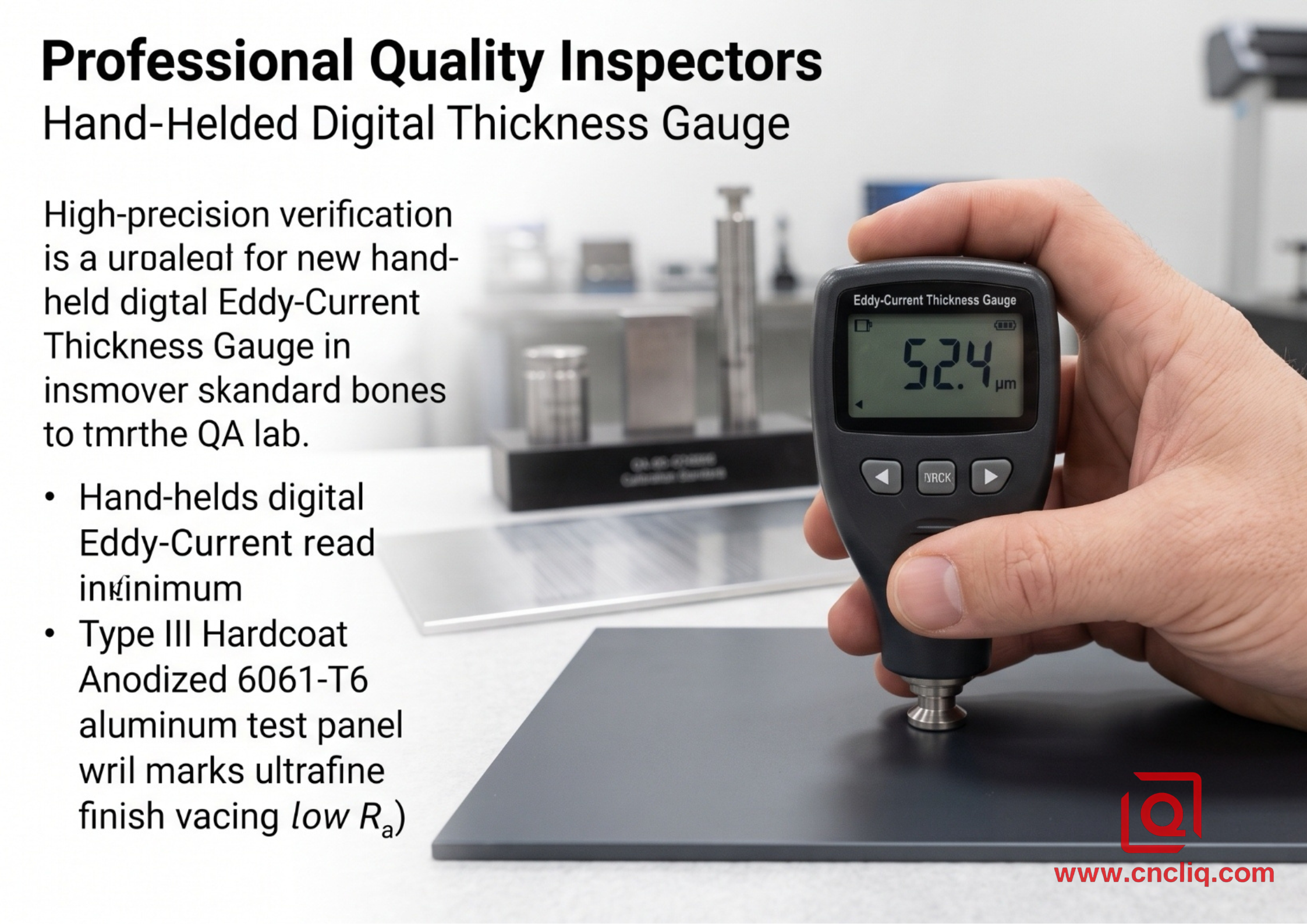
Thickness Verification: Use an Eddy-Current Thickness Gauge (ISO 2360 / ASTM B244). Measure minimum 5 points per panel. Reject batch if standard deviation exceeds 3.5μm across a 300×300mm surface.
-
Seal Quality Test (Acid Dissolution Test per ASTM B680): Dip part in nitric/phosphoric acid solution (35ml/L H₃PO₄ +20g/L CrO₃ @38℃) for 15 minutes. Weight loss must be <40mg/dm². Unsealed or poorly sealed pores absorb ambient oils, showing finger-mark stains that cannot be solvent-cleaned.
-
Thread Go/No-Go Inspection: Test all pitch diameters using ANSI/ASME B1.2 Class 6H plug gages after sealing.
Need DFM Engineering Feedback on Your CNC Aluminum Parts?
Send your native STEP files and GD&T drawings directly to our engineering desk at Ningbo Liqin Industrial & Trading Co., Ltd. We will run full CAM toolpath pre-compensation, calculate exact anodize growth offsets, and output CMM inspection reports for your tight-tolerance components.
FAQs
Q1: Can we machine localized critical features after anodizing?
A: Yes, but watch out for tool chatter. Carbide endmills will instantly chip when striking the brittle 60 HRC Al₂O₃ skin. Use Diamond-Coated or PCD tools, step down in 0.05mm light cuts, and flush with coolant to prevent boundary delamination.
Q2: How do you protect precision ground surfaces or conductive grounding pads during Type III Hardcoat Anodizing?
A: Liquid rubber masking (like AC-350) or custom precision-molded silicone plugs.
For tight-tolerance bores (under ±0.005mm), don't trust chemical tape—acid creeps under edges. We machine 0.2 mm oversized rubber bungs, press-fit them into the channels before dipping, and peel them post-seal. Expect a 0.15mm edge-feathering transition zone around masked boundaries; factor that clearance into your assembly design.
Q3: Why does 7075 aluminum look darker or yellower than 6061 after clear anodizing?
A: Material chemistry. AL7075 contains 5.1–6.1% Zinc and 1.2–2.0% Copper. During anodic oxidation, intermetallic phases dissolve unevenly and get trapped in the oxide layer. If cosmetic color uniformity across an assembly is mandatory, do not mix 6061 and 7075 parts in the same anodizing rack.
Q4: How do I dimension threads on drawings to ensure 6H fit after hardcoat?
A: Mark it on the print: M12x1.5-6G PRE-PLATE TAP / MIL-A-8625 TYPE III CLASS 1 POST-PLATE 6H FIT. Let the shop handle tap sizing.
Q5: Will anodizing fill micro-porosity in die-cast or extruded aluminum?
A: No. It bleeds.
Acid traps inside sub-surface voids during dipping. Hours after sealing, residual sulfuric acid oozes back out, creating ugly white blooming spots that ruin the finish and cause localized corrosion. For cast aluminum (like A380/A356), always specify resin vacuum impregnation prior to anodizing, or switch to CNC-machined wrought 6061-T6 billet.
Summary
Precision aluminum machining and anodizing can’t be managed as two isolated processes. Controlling tight tolerances requires calculating the 50% penetration and 50% growth ratio of the oxide layer, applying pre-compensation directly to your CAM toolpaths, and selecting the right surface finish early in the design stage. Machining smart upstream eliminates costly thread seizing, bore collapse, and scrap downstream.
Contact Information
Disclaimer
The engineering parameters, tolerance compensations, and process recommendations provided in this article are based on general industry standards (such as MIL-A-8625) and standard shop-floor practices. Machining outcomes and anodizing film thickness may vary depending on specific aluminum alloy compositions, bath chemistry, and toolpath conditions. Always validate critical dimensions through physical prototyping and first-article testing before full production.
Liqin Manufacturing Team
We are Ningbo Liqin Industrial & Trading Co., Ltd.,a professional manufacturer with over 18 years of experience in high-precision custom metal parts. We specialize in CNC machining, forging, die casting, and cold extrusion processes, serving industries such as automotive, medical, aerospace, electronics, and more. Our factory covers an area of 6,500 square meters and is equipped with 150+ advanced machines, including:
- CNC machining centers (4-axis, 5-axis)
- CNC lathes and turning-milling complexes
- Cold extrusion equipment (250T–650T)
- Die casting machines
We adhere to ISO9001, ISO13485: 2016, and IATF16949: 2016 standards, implementing end-to-end quality management: In-process quality control (IPQC), final quality control (FQC), outgoing quality control (OQC). CMM, projectors, hardness testers, and salt spray test equipment. Our products are exported to North America, Europe, Asia, and Oceania. We offer:
- One-stop service from design to delivery
- Quick response within 2 hours for quotes and technical support
- Custom solutions based on your drawings or samples
Welcome your inquiries and samples. Visit our website or contact us directly for a competitive quote!
