 English




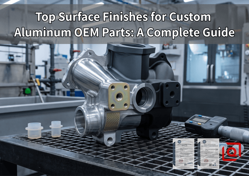
Milling a billet block down to tight prints feels rewarding on the floor. Until shop air takes over. Fresh 6061 or 7075 cuts start reacting with oxygen in seconds, growing a patchy native oxide layer merely 2 to 5 nanometers thin. This bare film picks up fingerprints, scuffs easily, and falls apart fast in humid or salty environments.
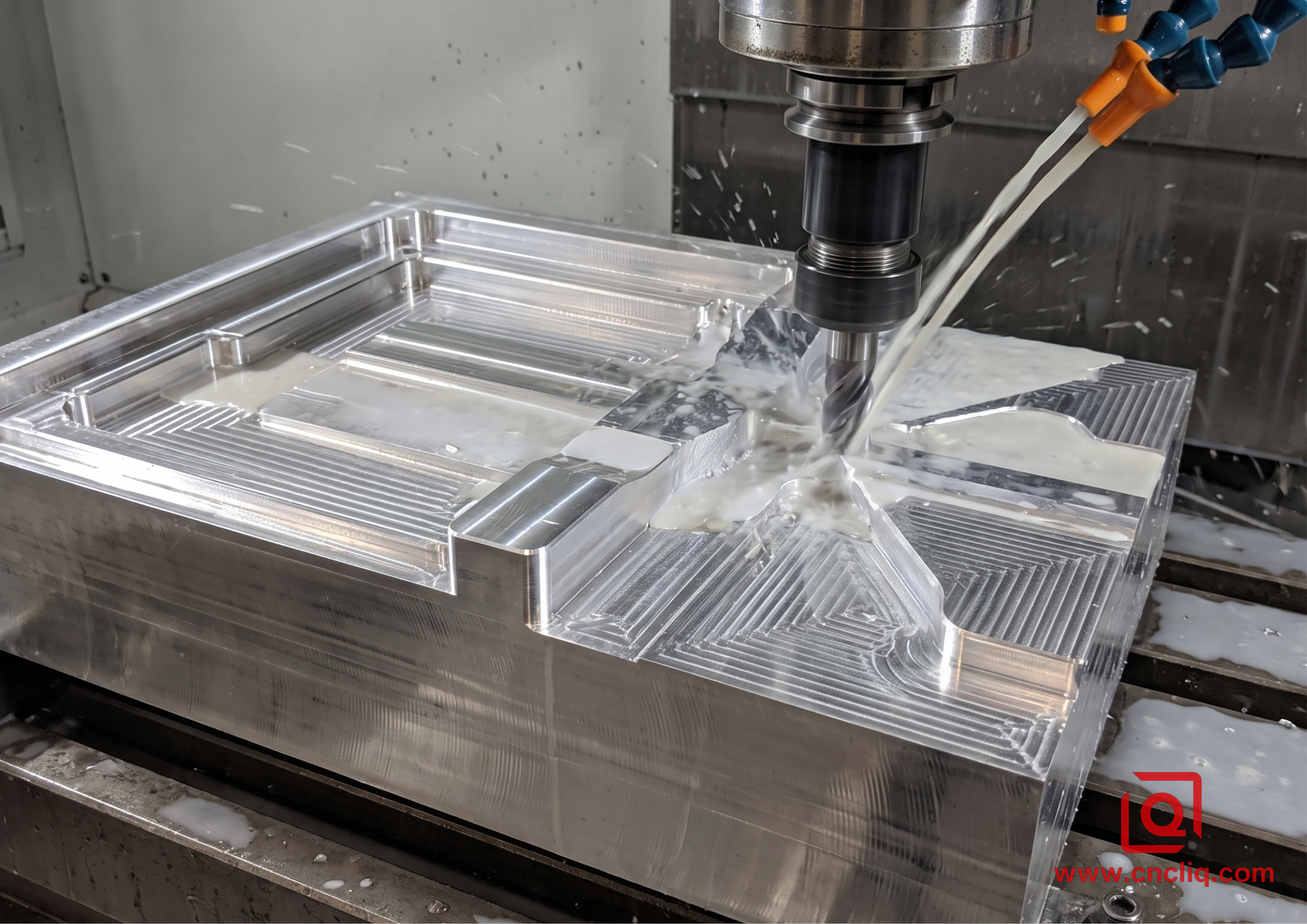
When engineers and procurement staff source custom aluminum OEM parts, surface treatment goes way beyond looks. Your print spec decides whether stainless hardware locks up under torque, an outdoor housing keeps out moisture, or mating faces grind down before 1000s of strokes.
Here is what these finishes actually do in the field, which standards matter, and the blueprint mistakes that stall the CNC line.
1. Type II Anodizing (Sulfuric Acid Anodizing)
Type II anodizing serves as the standard baseline for aluminum OEM manufacturing across industrial and consumer sectors. Governed worldwide by MIL-A-8625 Type II, Class 1 (Clear) and Class 2 (Dyed) as well as ISO 7599, this electrochemical immersion transforms the raw metal surface into a durable, porous honeycomb of aluminum oxide.
Raw Machined Part ➔ Alkaline Clean ➔ Chemical Etch & Deoxidize ➔ Sulfuric Acid Bath (15% to 20% concentration at 20°C) ➔ Organic Dye Tank ➔ Hot Nickel Acetate Seal (96°C to 100°C) .
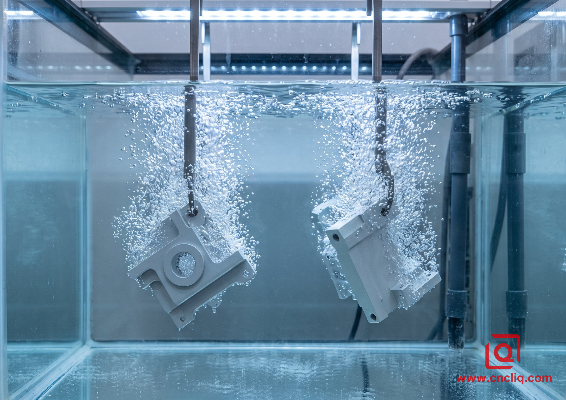
Parts get racked onto conductive titanium or aluminum fixtures, then dropped into a chilled sulfuric tank. Running direct current forces oxygen ions into the base metal, turning raw aluminum into a tight, even oxide skin from the outside in.
 +------------------------------------------------------------+
           |        Nickel Acetate Seal Layer |
           +------------------------------------------------------------+
           |  Porous Oxide Layer (Absorbs Color Dye) | 50% Penetration into base metal
===========+================================================+====================================
--- Original Machined Surface Baseline ---
===========+================================================+====================================
           |  Dense Barrier Oxide Layer | 50% Outward Dimensional Growth
           +------------------------------------------------------------+
           |  Raw Aluminum Alloy Core (e.g.6061-T6)     |
           +---------------------------------------------+
Critical Shop-Floor Reality: The 50/50 Growth Rule
Fresh prints frequently assume anodizing is just a topcoat like paint, but tank chemistry works differently. The layer forms on a strict 50/50 split: half the thickness penetrates the raw substrate, while the remainder expands outward.
Take a print specifying a 15-micron (0.015 mm) build:
-
7.5 microns of substrate is consumed inward.
-
7.5 microns builds outward on each face.
-
A critical reamed pin hole or internal bore will shrink by 15 microns (0.015 mm) in total diameter.
When machinists hold tight bearing bores on the CNC mill without offsetting for this growth, components return from the plating tanks undersized, requiring manual hand-polishing or scrap disposition.
Best practice: Always state on the drawing notes whether dimensions apply before or after plating.
2. Type III Hardcoat Anodizing (Hard Anodizing)
Subject standard Type II coatings to non-stop rubbing, abrasive debris, or scouring hydraulic jets, and that surface skin burns right off. Brutal wear regimes demand Type III Hardcoat, built to MIL-A-8625 Type III, Class 1/2 and ISO 10074 standards.
We run hardcoat tanks cold—cranking high current density in an acid bath chilled right down to 0°C to 5°C. Dropping the temperature stalls natural acid attack just enough for the electric drive to force rapid build-up, locking submicron pore columns into an ultra-tight ceramic barrier between 25 and 75 microns (0.025 to 0.075 mm) thick.
Dialed in on temper-hardened stock like 6061-T6, microhardness hits 400 to 550 HV, giving lightweight aluminum the working friction profile of case-hardened steel.
Workshop Realities & Engineering Compromises
-
Base Metal Color Shifts: Tight oxide pores lock in raw alloying constituents like silicon, iron, and copper. This chemistry naturally pulls bare aluminum into a deep slate charcoal or uneven bronze-olive tint straight out of the tank—no dye added. Deep black dye takes well, but bright cosmetic colors like vibrant red, clear blue, or gold cannot be achieved.
-
Fatigue Life Penalty: Hard anodic layers are rigid and non-ductile. Under heavy cyclic bending or dynamic vibration, microscopic micro-cracks form naturally within the brittle oxide skin, concentrating stress and lowering the fatigue limit of structural components by 15% to 30%. Never specify thick hardcoat on high-deflection spring clips or cyclic flexure arms unless wear resistance is strictly required.
3. Chemical Conversion Coating (Chem Film / Alodine)
Chemical conversion coating—widely referenced under trade names like Alodine or Iridite—is an immersion passivation process defined by MIL-DTL-5541 Type II (Hexavalent Chromium-Free, RoHS compliant), Class 1A and Class 3.
Unlike anodizing, chem film requires no electrical rectifiers or power supplies. It relies on a controlled chemical reaction between the bath chemistry and the aluminum surface, forming an ultra-thin, microscopic passivated barrier measuring just 0.2 to 1.0 micron (0.0002 to 0.0010 mm).
+-----------------------------------------------------------------------------------------+
|  Class 1A: Engineered for maximum corrosion prevention (surpasses 168 hours salt spray)  |
|  Class 3: Engineered for low electrical contact resistance while preventing oxidation    |
+-----------------------------------------------------------------------------------------+
When to Select Chem Film
- True-to-Print Dimensions: The conversion film builds up far below standard machining roughness limits, leaving nominal CAD models, thread pitch diameters, and close-tolerance pin bores completely unchanged on the CMM.
- Bare-Metal Continuity & RF Shielding: Class 3 finishes maintain true surface conductivity. That makes them the hard requirement for avionics enclosures, RF filter housings, and earthing pads where an anodized shell would simply insulate the circuit.
- Primer & Bonding Anchor: Chromate passivates live aluminum on contact, killing off sub-surface creep while biting hard into topcoats so powder lines and structural epoxies never peel.
4. Powder Coating
If aluminum weldments or frames need bold cosmetic branding, heavy stipple textures, ding resistance, or non-stop outdoor exposure to UV and driving rain, powder coat is the go-to production call under AAMA 2604 and Qualicoat Class 2.
We feed dry-milled polymer blends—mostly polyesters, urethanes, or tough epoxies—through high-voltage spray nozzles that throw a static charge straight at grounded aluminum racks. The airborne cloud wraps every exposed flank evenly. From there, the whole load heads into the bake oven at 180°C to 200°C for 15 to 20 minutes, kicking off full resin cross-linking to flow out into a tough, monolithic skin.
Cleaning & Chemical Pre-treatment ➔ Moisture Dry-Off (110°C) ➔ Electrostatic Powder Application ➔ Convection Oven Bake (190°C,15 min) ➔ Cooling & Visual Inspection
========================================================================================================================================================================================
  Cross-Linked Powder Coat Resin Shell (60 to 110 microns thick) .---------------------------------------------------------------------------------------------------------------------------------
  Pre-treatment: Micro-thin Chem Film Passivation (Under 1 micron)
====================================================================
  Aluminum Base Metal (6000 / 5000 Series)
====================================================================
Shop-Floor Red Flags
- Plug Those Holes or Chase Threads: Powder stacks on thick—expect 60 to 110 microns (0.060 to 0.110 mm) added per face. If your prints miss callouts for high-temp silicone mask plugs in tight holes like M3, M4, or M5, liquid resin floods the root. You’ll end up manually re-tapping every thread, wrecking your cycle times.
- Watch the Oven Soak: Holding 200°C for a 20 minutes bake can over-temper heat-treated series like 7075-T6.Let the thermal curve drift uncontrolled, and you risk knocking the top end right off your design yield strength.
5. Mechanical Pre-Finishes: Bead Blasting & Brushing
Plating tanks don't hide metal defects; they hold up a magnifying glass.Pull a fresh billet off the CNC spindle with heavy step-over scallops and cutter ridges, and a Type II clear bath will highlight every single flaw instead of burying it.
Bead Blasting: Blast cabinets blast fine glass or ceramic media under line air pressure, hammering the skin into an even, zero-direction satin texture. That light peening knocks down raw milling tracks, leaving a clean, anti-glare finish standard across medical consoles and high-end handhelds.
Linear Brushing (Belt Grit): Feed parts straight over abrasive belts or Scotch-Brite flap wheels to lay down parallel, straight-line grain runs that play up the raw metallic shine.
Shop-Floor Golden Rule: On external faceplates and bezel covers, always blast before Type II dip—it wipes directional glare and keeps cosmetic surfaces uniform.
6. Technical Comparison Matrix
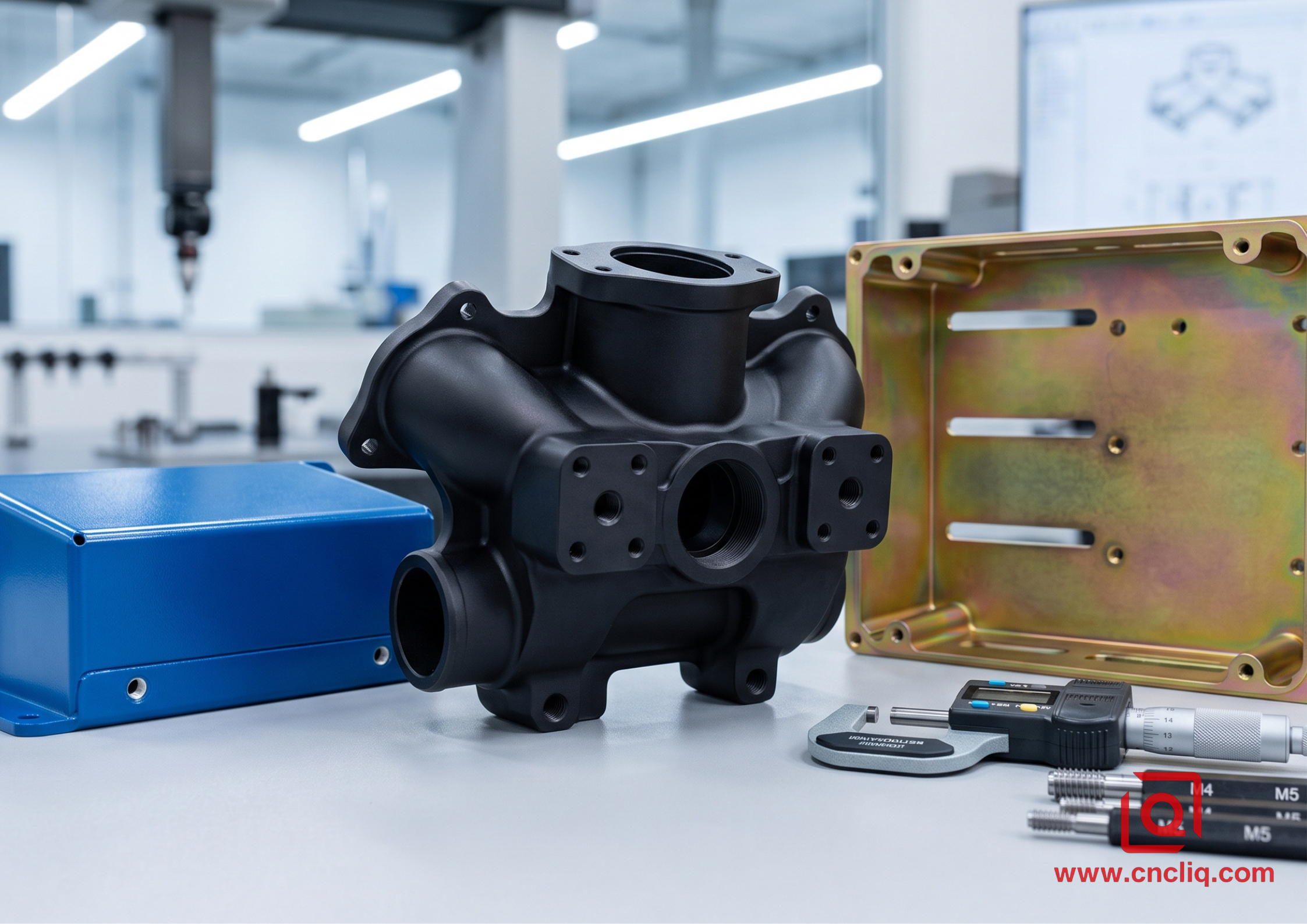
| Finishing Process | Typical Thickness | Dimensional Change (Per Surface) | Surface Hardness | Electrical Conductivity | Standard Specification |
| Type II Anodizing | 10 to 25 microns | +5 to +12.5 microns | 250 to 350 HV | Non-conductive (Insulator) | MIL-A-8625 Type II |
| Type III Hardcoat | 25 to 75 microns | +12.5 to +37.5 microns | 400 to 550 HV | Non-conductive (Dielectric) | MIL-A-8625 Type III |
| Chem Film (Alodine) | 0.2 to 1.0 micron | Negligible (Under 0.5 micron) | Same as base alloy | Electrically conductive | MIL-DTL-5541 Type II |
| Powder Coating | 60 to 120 microns | +60 to +120 microns | 2H to 4H Pencil Hardness | Non-conductive | AAMA 2604 / Qualicoat |
| Bead Blast + Type II | 12 to 25 microns | +5 to +10 microns | 250 to 350 HV | Non-conductive | MIL-A-8625 Type II |
7. Real-World Case Breakdown: The Multi-Functional Sensor Housing
The Engineering Challenge
An aerospace technology client partnered with our engineering team to manufacture an environmental optical sensor enclosure milled from solid 6061-T6 aluminum.
                                  [ Optical Sensor Array ]
                                             |
                                   +-------------------+
        Internal Grounding Path ➔ | Sensor Base Flange| (Requires Class 3 Chem Film)
                                   +-------------------+
                                   | Outer Housing Body| (Requires Bead Blast + Matte Black Type II)
                                   +-------------------+
                                             |
                               (Internal Sealed Sensor Chamber)
The component had to meet three strict operational requirements on a single continuous workpiece:
-
The exterior surface required an anti-glare, non-reflective matte black finish to avoid scattering external optical beams.
-
The internal sensor mounting pad needed full electrical continuity to the chassis, maintaining low contact resistance to dissipate static build-up and shield sensitive sensors against radio-frequency interference (RFI).
-
Four precision internal alignment dowel pin holes required a tight positional tolerance of ±0.008 mm to align sensitive optical lenses.
The Initial Drawing Risk
The initial drawing revision arrived with a single broad surface note: "Hardcoat Anodize Black per MIL-A-8625 Type III, Class 2, 50 microns thickness on all surfaces."
Executing the part directly under this blanket note would have caused two assembly failures:
-
The thick dielectric hardcoat would have insulated the internal mounting pad, completely eliminating electrical grounding and leaving the internal sensor vulnerable to electromagnetic noise.
-
The 50-micron oxide growth would have reduced the precision dowel pin holes by nearly 0.050 mm, preventing optical locating pins from seating and causing mechanical binding.
Manufacturing Strategy & Routing Plan
Our DFM engineering team revised the process routing and executed a multi-stage finishing procedure:
-
Machining Pre-Compensation: Using 5-axis CNC machining centers, toolpaths for the four dowel pin bores were pre-reamed with an offset of +0.025 mm to account for subsequent chemical etching and oxide growth.
-
Full-Body Chemical Passivation: The entire raw enclosure was submerged in a MIL-DTL-5541 Type II Class 3 bath, creating a micro-thin, conductive conversion film across all internal cavities, threads, and mounting flanges.
-
Precision Masking: Operators applied custom-fitted silicone plugs into the threaded dowel holes and placed die-cut chemical-resistant masks over the internal electrical grounding pad.
-
Controlled Bead Blasting: Exposed outer exterior surfaces received an automated glass bead blast using fine media, erasing CNC tool marks and preparing the surface for uniform matte dyeing.
-
Selective Type II Anodizing: The unmasked outer surfaces underwent MIL-A-8625 Type II, Class 2 (Matte Black) anodizing targeted at a controlled 15-micron thickness, sealed in a heated nickel acetate solution.
-
De-Masking & Quality Verification: Protective plugs and masks were removed, followed by ultrasonic cleaning. Inspection on the coordinate measuring machine (CMM) confirmed that dowel pin locations held within the ±0.008 mm tolerance, while micro-ohmmeter testing confirmed clean electrical continuity across the grounded mounting pad.
8.Practical Rules for Specifying Aluminum Finishes on 2D Drawings
1. DEFINE DIMENSION TIMING ➔ State whether drawing dimensions apply BEFORE or AFTER surface finishing.
2. PROTECT FINE THREADS   ➔ Explicitly note masking on M4 and smaller internal tapped holes.
3. IDENTIFY RACKING ZONES  ➔ Designate non-critical surfaces where electrical racking marks are acceptable.
4. ACCOUNT FOR ALLOY TYPE ➔ Remember that 2000 & 7000 series aluminum yield darker, earthier anodized tones.-
State Dimensional Timing Clearly: Never leave drawing callouts ambiguous. Include an explicit note:
"All drawing dimensions and tolerances apply AFTER surface treatment"or"Dimensions apply BEFORE plating."This allows the CNC programming team to apply accurate cutter compensation offsets before machining. -
Explicit Masking Boundaries: For grounding pads, high-tolerance bearing bores, or small internal threads (M4 and below), mark the specific zones on your print with hatching and add a clear note:
"Mask from Anodizing / Powder Coat - Chem Film Only." -
Designate Racking Contact Zones: Anodizing requires firm electrical contact via titanium or aluminum fixtures, which leaves tiny un-anodized contact points (1 to 2 mm). Note acceptable clamp locations on non-cosmetic interior walls (such as
"Racking contact permitted on inside recess face B only"). -
Match Expectations to Alloy Composition: Alloy chemistry directly influences color and appearance. Machined 6061-T6 takes dyes evenly with crisp color matching. Drop high-strength 7075-T6 in the same rack, and its heavy zinc load will cast a muddy, olive tint. As for high-silicon casting alloys like A380 or ADC12, anodize baths leave them blotchy and gray; keep cast housings on chem film or powder lines instead.
FAQs
Q1: How does anodizing shift part dimensions and hole tolerances?
Paint and electroplating simply stack on the exterior, but anodizing actually consumes the base aluminum. The layer forms on a strict 50/50 split: 50% bites into the substrate, 50% pushes out. Specify a 15-micron coating, and each wall gains 7.5 microns—tightening any finished inside diameter by a total of 15 microns. Machinists need to offset toolpaths upfront on tight pin bores, or parts will return from the tanks undersized.
Q2: Can die-cast aluminum alloys achieve a clean cosmetic anodized finish?
Skip it for appearance-critical parts. Die-casting grades like A380 carry heavy silicon loads for melt fluidity, but that silicon bleeds out during anodizing, leaving a muddy, streaky grey mess. If you want uniform cosmetics on cast housings, go with electrostatic powder coat or a chromate conversion film instead.
Q3: What makes Chem Film a better call than standard Type II anodize?
Spec Chem Film (Alodine) whenever mating surfaces need direct electrical continuity—think RF shielding enclosures or chassis ground pads. Standard anodic films act as non-conductive dielectric barriers that break ground circuits. Chem Film adds virtually zero measurable build (under 1 micron), so it protects tight slip-fit pins and precision bores without blowing your dimensional stack.
Q4: Why does Type III Hardcoat knock down fatigue life under cyclic loads?
Hardcoat yields a glass-hard (400 to 550 HV) ceramic shield that shrugs off abrasive sliding wear. The catch is brittleness. Under dynamic vibration or cyclic bending, tiny micro-cracks form across the rigid oxide crust. These fractures turn into sharp stress risers, biting into the base alloy and dropping structural fatigue strength by 15% to 30%.
Q5: How do you stop powder coating from packing into internal threads?
Powder leaves a heavy film—roughly 60 to 110 microns per side—and molten resin easily floods unprotected threads inside the curing oven. The simplest shop-floor fix is pressing reusable high-temp silicone taper plugs into tapped holes prior to spray. That keeps thread roots clean and saves you from manually chasing threads on the bench later.
Summary
Specifying the right finish for aluminum hardware means juggling mechanical loads, conductivity, tight tolerances, and whatever weather it hits. Run Type II with a bead blast for solid corrosion defense and clean cosmetics. Hit severe sliding wear with Type III Hardcoat. Need bare-metal grounding and zero dimensional shift? Call out Chem Film. For outdoor beating and impact survival, stack on thick powder coat.
If you plan ahead for thickness build-up—like the 50/50 anodize split—mask your fine threads, and clearly flag "before/after finish" tolerances on your 2D prints, those raw billets will clear assembly without nasty shop-floor surprises.
Contact Information
Disclaimer
All technical articles, material specifications, machining recommendations, and surface treatment details published on this blog are for informational and reference purposes only. Please note that general blog insights do not replace signed technical agreements. Because custom parts vary by material heat numbers, machine calibrations, and specific tolerances, binding quality specs are governed solely by your approved CAD drawings, signed contracts, and formal quality plans.
All customer case studies featured on this blog have been thoroughly anonymized and sanitized.The performance metrics, manufacturing workflows, and imagery displayed serve solely to demonstrate our custom machining capabilities and do not represent a single universal standard for all orders.
Liqin Manufacturing Team
Built on 18 years of precision engineering experience, Ningbo Liqin Industry manufactures high-tolerance metal components for demanding global markets. We operate out of a 6,500 m² production hub equipped with over 150 machines, running 4-axis and 5-axis CNC machining, mill-turn machining, cold extrusion, and pressure die casting under one roof. This setup allows us to manage projects seamlessly, taking parts from initial CAD concepts directly to finalized shipments.
We handle quality control with zero compromise. We treat tight tolerances with the engineering discipline they require. Backed by ISO 9001, ISO 13485, and IATF 16949 certifications, our QA engineers run strict IPQC, FQC, and OQC checks on every single production batch. From CMM dimensional mapping and optical profiling to hardness and salt-spray testing, we validate your critical specs upfront—so you receive drop-in ready components with zero assembly headaches or costly line stoppages. On top of manufacturing, you can rely on us for two-hour response times on new RFQs, direct support for prototype sampling, and smooth export shipping across Europe, North America, Asia, and Oceania.
Welcome your inquiries and samples.Visit our website or contact us directly for a competitive quote!
