 English




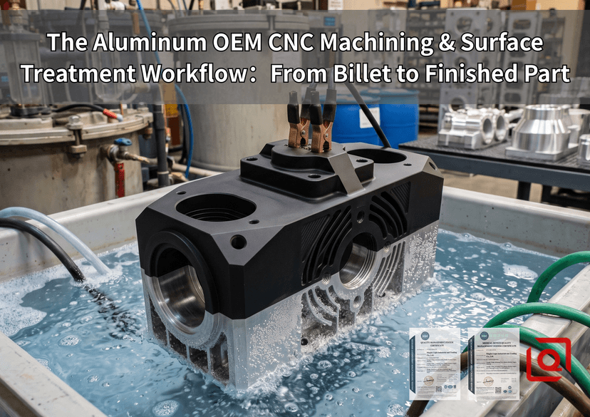
Every sourcing manager and mechanical engineer has lived through this scenario. You finalize a 3D model, set strict geometric dimensioning and tolerancing callouts on your 2D manufacturing prints, approve a golden sample, and release a purchase order for mass production. A few weeks later, the shipping crates arrive at your receiving dock. When your assembly technicians attempt to slide a precision ground stainless steel shaft into an anodized aluminum bore, the assembly line freezes. The fit is either binding completely or wobbling with excessive play. You drop the batch at QC, only for the CMM readout to flag a 0.030 mm bore blowout past nominal—meanwhile, the anodizing came back milky, streaky, and splotchy across the entire run.
Ring up the CNC shop, and they instantly pass the buck to the plater, insisting the batch got torched in the acid etch. Dial the anodizer next, and you get the exact opposite story: the incoming stock was chewed up with micro-scratches, rough step-overs, and burnt-on coolant gumming up the pores.
This endless blame game happens because far too many suppliers treat CNC cutting and surface finishing as two isolated, disconnected operations handled by different entities.
In custom aluminum manufacturing, every single operational choice made inside the CNC enclosure directly dictates how that raw metal responds when submerged in chemical transformation baths. Whether you are hogging out structural brackets from aerospace-grade 7075-T6 or face-milling complex fluid manifolds from 6061-T6, machining and chemical post-processing must be treated as a single continuous engineering sequence.
Step 1: Raw Material Verification and Internal Stress Normalization
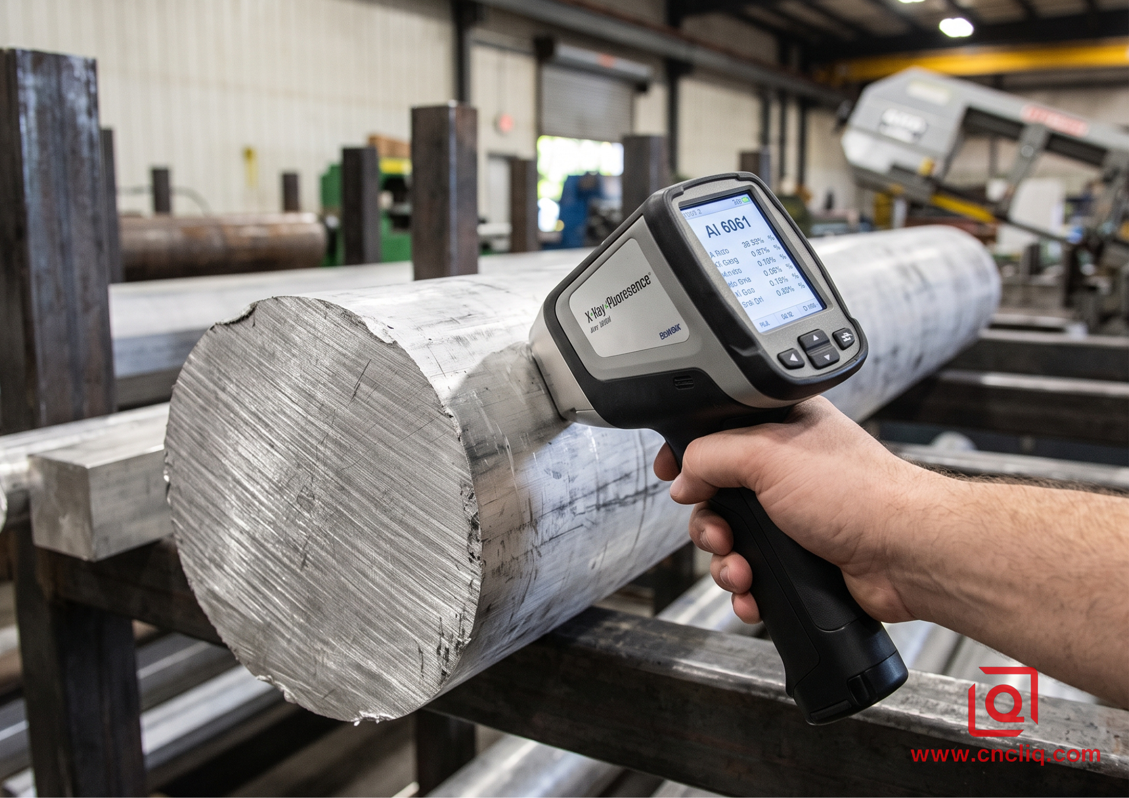
A common mistake in custom manufacturing is assuming every piece of raw bar stock or extruded block matches the nominal properties on the mill certificate. When raw aluminum billets roll out of an extrusion press or cold-rolling mill, massive internal tensile and compressive residual stresses remain locked deep within the core grain structure.
Raw Billet Cut-off ➔ Face Milling Datum-A ➔ Stress Equalization Soak ➔ Rough Hogging
If you mount an as-extruded billet directly into machine vise jaws and immediately cut deep cavities, material tension releases unevenly. The part relaxes, shifts, and bows while the cutter is still spinning. By the time you unclamp the fixture jaws, your flat mounting face warps into an arch, ruining your 0.015 mm flatness tolerance.
To prevent raw stock instability:
-
We scan raw incoming stock with an X-ray fluorescence alloy analyzer to verify element percentages before issuing stock to the saws.
-
For thin-walled enclosures and asymmetrical structural housings, our CAM programmers divide machining into two distinct setups. We rough hog approximately 85% of the bulk cavity volume, completely unclamp the workpiece from the vise, and allow the semi-machined part to sit on an equalization bench for 4 to 6 hours.
-
This intermediate resting stage lets the aluminum grain structure normalize and equalize its mechanical tension at room temperature. Only after this stress-relief stage do our technicians reload the part with light, uniform clamping torque to perform the final precision finishing cuts.
Step 2: High-Speed Precision CNC Machining & Datum Integrity
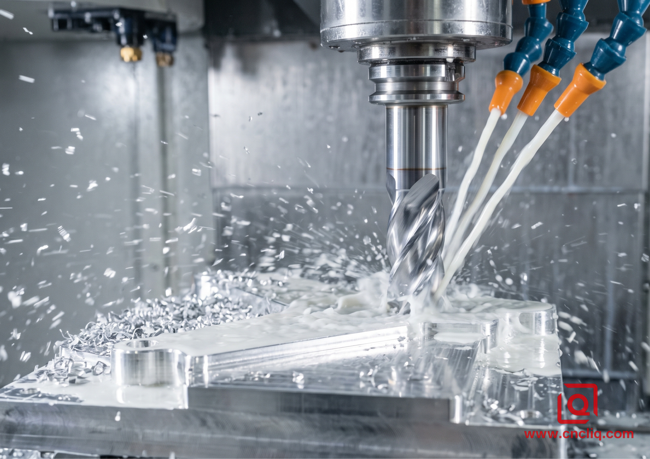
Sure, aluminum cuts like butter, but its material quirks trigger real headaches: severe thermal growth and a nasty habit of galling inside the flutes.Jam the feed too hard or starve the coolant, and that friction liquifies swarf in a heartbeat—fusing raw slug onto the insert tip and shredding the finished surface.
Rough Cavity Hogging ➔ Semi-Finish Contours ➔ Tool Wear Verification ➔ Final Precision Bore Finishing
Our machinists eliminate built-up edges and dimensional thermal drift using dedicated tooling and process setups:
-
Tool Geometry Setup: We spin 3-flute micro-grain carbide end mills ground with mirror-slick, polished gullets and shielded in ZrN or DLC film.That ultra-slick channel flings blistering swarf clear out before frictional heat can fuse melted stock against the tool body.
-
Coolant Management: Flood coolant nozzles cannot clear chips out of deep pocket pockets. We employ high-pressure through-spindle coolant delivery at 70 bar directly through the cutting tool core. This setup blasts chips out of pockets in milliseconds while stabilizing the cutting zone at an ambient 20°C.
-
Single-Setup 5-Axis Multi-Sided Machining: When machining multi-sided housings with compound angled cross-holes, repositioning a workpiece across multiple three-axis vise setups introduces datum stacking errors. Every manual re-clamping introduces between 0.010 mm and 0.020 mm of true position error. We load complex parts onto 5-axis trunnion machining centers, accessing five distinct faces in a single clamping setup to maintain true position within 0.008 mm relative to primary datums.
Material Selection & Machining Parameter Reference
| Metric & Property | Grade: AL 6061-T6 | Grade: AL 7075-T6 | Grade: AL 5052-H32 |
| Yield Strength | 276 MPa | 503 MPa | 193 MPa |
| Machinability Rating | 80% (Smooth chip clearance) | 70% (Hard, short brittle chips) | 50% (Gummy, prone to burrs) |
| Linear Cutting Speed | 350 to 600 m/min | 300 to 450 m/min | 200 to 350 m/min |
| Standard CNC Tolerance | 0.015 mm | 0.010 mm | 0.030 mm |
| Primary Applications | Electronic housings, manifolds | Aerospace structural brackets | Sheet metal housings, marine parts |
Step 3: Deburring and Surface Preparation (Pre-Anodize Processing)
Never dump a raw milled part straight off the fixture into the anodize tanks. OEM jobs constantly blow up because folks treat deburring like some cosmetic option. Stray fuzz hooked on thread starts, paper-thin wire edges hugging the bevels, or cutter cusp lines? Anodize won't mask a thing. The acid tank gnaws straight into those spots, digging into parent stock and ballooning negligible blemishes into obvious reject material.
Manual Micro-Deburring ➔ Ultrasonic Degreasing ➔ Media Bead Blasting ➔ Cleanliness Inspection
-
Micro-Edge Finishing: Operators scan every seam, intersecting port, and step under 10x stereo optics. Working with ceramic dressers and manual deburr hooks, they wipe off all razor edges to hold a clean, uniform 0.100 mm to 0.200 mm edge break.
-
Multi-Tank Sonic Wash: Raw-milled aluminum traps fine cutting fluid and high-pressure additives down in the grain. We dunk the run into a churning, heated alkaline bath at 55°C for 12 minutes. High-frequency transducers pop micro-cavitation bubbles right inside blind threads, stripping out stuck grease.
-
Automated Bead Blasting: When a uniform matte aesthetic is required, parts move into automated tumble-blasting cabinets using 120# fine spherical glass media at a consistent nozzle pressure of 0.40 MPa. This eliminates directional toolpath marks and produces an even, clean surface roughness of Ra 1.2 micrometers.
Step 4: Industrial Surface Treatment & Dimensional Growth Compensation
Anodizing bears zero resemblance to running powder coat or shooting wet paint. You are not slapping a separate skin onto the metal; an electro-chemical tank actually converts parent aluminum into an ultra-hard alumina structure—building 50% inward into the substrate and 50% outward from the original boundary.
Alkaline Wash ➔ Acid Deoxidize ➔ Sulfuric Anodic Bath ➔ Color Dye Soak ➔ Hydrothermal Sealing
A common engineering trap is adding an anodizing callout to a drawing without accounting for dimensional stack-up. For standard Type II sulfuric acid anodizing, the resulting oxide film penetrates into the metal substrate by 50% and grows outward beyond the original physical boundary by 50%.
When your prints call out heavy-duty Type III hardcoat anodizing per MIL-A-8625 Type III Class 1 with a specified coating thickness of 0.050 mm (50 micrometers), your part's exterior dimensions grow outward by 0.025 mm per surface, while internal bores and threaded holes shrink inward by 0.025 mm per side.
Original Pre-Plate Machined Diameter
       │
       ├── Exterior Boss Profile: Grows +0.025 mm outward per side (+0.050 mm total OD growth)
       └── Interior Bore Profile: Shrinks -0.025 mm inward per side (-0.050 mm total ID reduction)
If your machine shop finishes an internal bearing bore exactly to nominal print dimensions prior to sending it to the plating line, the hardcoat oxide build-up will close down the internal diameter. The bearing will not press in without galling or cracking the housing.
To guarantee perfect post-treatment fits:
-
Our CAM programmers apply custom tool offset compensation tables during the final finishing pass, cutting internal bore diameters oversized and exterior journal diameters undersized by the exact expected plating growth.
-
For tight internal threads (such as M3 or M4 tapped holes) that cannot tolerate dimensional closure, our technicians insert custom tapered silicone masking plugs before the parts enter the acid bath.
Surface Finishing Process Selection Guide
| Surface Treatment | Industry Specification | Film Thickness | Layer Hardness | Operational Purpose & Surface Quality |
| Type II Anodize | ISO 7599 / MIL-A-8625 Type II | 0.008 to 0.015 mm | 300 HV | Cosmetic coloring, corrosion protection, consumer electronics |
| Type III Hardcoat | MIL-A-8625 Type III Class 1/2 | 0.035 to 0.060 mm | 500 HV | Wear resistance, electrical insulation, hydraulic cylinders |
| Chemical Film (Chromate) | MIL-DTL-5541F Type II Class 3 | Under 0.001 mm | Base Metal | Electrical grounding paths, low contact resistance, paint primer |
| Electroless Nickel Plating | ASTM B733 Class 1 | 0.010 to 0.025 mm | 600 HV | Chemical washdown resistance, high surface hardness, sliding tracks |
Real-World Engineering Case: Industrial Robotic Vision Housing
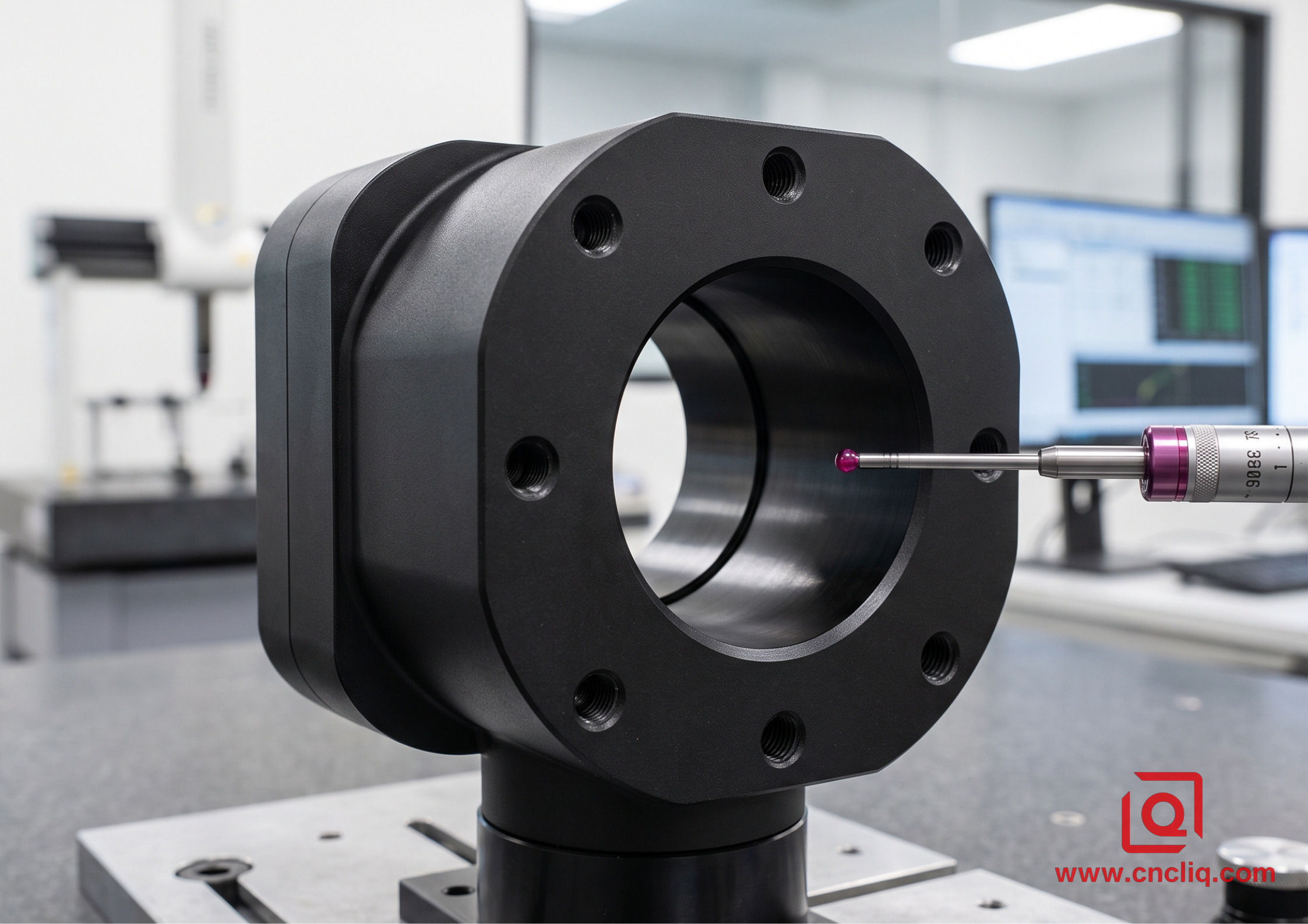
A European industrial automation client required a batch of precision optical mounting enclosures for an automated robotic inspection line. The component features a critical central optical tube bore, high aesthetic requirements, and demanding environmental durability specifications.
    ┌────────────────────────────────────────────────────────┐
    │              Robotic Vision Sensor Housing             │
    │                                                        │
    │   Critical Features:                                   │
    │   • Central Bore: 32.000 mm (+0.012 / -0.000 mm) H7    │
    │   • True Position: 0.015 mm relative to Datums A & B   │
    │   • Coating: MIL-A-8625 Type III Class 2 Matte Black   │
    │   • Specified Coating Thickness: 0.040 mm ± 0.005 mm   │
    └────────────────────────────────────────────────────────┘
The Engineering Challenges
-
The tight 32.000 mm bore (+0.012 / -0.000 mm H7 fit) required a flawless sliding fit for a multi-lens optical barrel.
-
The customer required a deep, non-reflective matte black MIL-A-8625 Type III Class 2 hardcoat anodize with a coating thickness of 0.040 mm to withstand continuous abrasive dust exposure in an automated factory environment.
-
Here is the rub: that 0.040 mm hardcoat chokes the inside diameter by 0.040 mm across the bore (0.020 mm buildup per side), which would pinch the finished hole well under the 32.000 mm bottom limit.
Our Production Solution
-
Pre-Plating CAM Bore Offset: Our programming team applied a pre-plating machining compensation offset. The central bore was CNC finish-bored to 32.040 mm (±0.004 mm), leaving room for the inward growth of the oxide film.
-
5-Axis Single-Setup Machining: We clamped the raw 6061-T6 block straight into a 5-axis trunnion mill, hitting the mounting pads, dowel locating bores, and that critical center hole in one shot. That single clamp locked the bore’s true position right within 0.008 mm back to Datums A and B.
-
Precision Masking of Fastener Holes: Custom tapered EPDM rubber plugs were installed in eight blind M3 mounting threads around the front face, protecting them from acid erosion and thread shrinkage.
-
Electrolyte Bath Temperature Control: Hardcoat anodizing typically yields a dark grey or bronze hue that resists deep black dye absorption. To produce a deep, non-reflective matte black finish, we dropped the sulfuric acid tank temperature to -2°C, utilizing pulsed direct current rectification and aggressive mechanical air agitation.
-
CMM Verification: Following hydrothermal deionized water sealing, 100% of the production lot underwent coordinate measuring machine probing. The final post-anodize internal bore diameters measured an average of 32.006 mm across the batch, positioned inside the customer's 32.000 mm to 32.012 mm H7 tolerance band.
Step 5: Final Quality Verification and Packaging
A precision aluminum component isn’t finished until the geometry checks out and the finish is locked down for overseas transit.
-
Coordinate Measuring Machine Inspection: Operating inside a temperature-controlled metrology lab kept at 20°C, our technicians run automated multi-point touch probes across critical datums, verifying concentricity, bore diameters, and surface profiles.
-
Eddy-Current Coating Thickness Testing: Using calibrated non-destructive eddy-current probes (in accordance with ASTM B244 standards), we measure coating thickness across high and low current density zones on each part to confirm consistent oxide coverage.
-
Export-Grade Packaging: Ocean transit is rough on anodized finishes—friction scuffs, salt fog attack, and vibration chatter happen easily. To stop this, we blow down finished parts with clean compressed air, pack each into its own VCI bag, and set them in tailored closed-cell polyethylene foam cutouts before loading into rugged corrugated cartons.
FAQs
Q1: How does anodizing film thickness affect critical bearing fits and tapped threads?
A: Type II sulfuric anodizing builds about 50% into the aluminum substrate and 50% outward, with Type III Hardcoat following that same 50/50 split at greater film thicknesses. Take a standard 0.050 mm hardcoat callout: external journal ODs expand by 0.050 mm overall (0.025 mm per surface), while internal bores close in by 0.050 mm. If you do not apply pre-machining dimensional offsets, tight H7 bearing bores and small internal threads (under M5) will bind. We solve this by boring critical diameters oversize during CNC finishing and applying custom silicone masking plugs to threaded holes before chemical immersion.
Q2: What is the primary difference between 6061-T6 and 7075-T6 for precision OEM parts?
A: At roughly 276 MPa yield, 6061-T6 machines predictably, takes decorative or hard anodize without color blotching, and keeps stock costs reasonable. It is the practical default for enclosures, mounting brackets, and manifold blocks. 7075-T6 jumps to 503 MPa yield strength—rivaling structural carbon steels—though heavy zinc alloying pulls the anodized baseline toward an off-tone, yellowish bronze.Reserve 7075-T6 for assemblies driven by strict strength-to-mass targets or severe fatigue cycles, like flight hardware links and dynamic robot limbs.
Q3: How do you stop thin-walled aluminum enclosures from warping during CNC milling?
A: Thin walls warp when internal stock stress clashes with heavy vise pressure. We counter this using a proven 4-step sequence: buy stress-relieved stock (like 6061-T651), hog out roughly 85% of bulk stock, then crack the vise open so the part settles for 4 to 6 hours. Next, hold parts down with vacuum chucks or profiled soft jaws to distribute clamping pressure over broad surfaces. Keep cuts fast and light—high-feed milling clears heat inside the evacuated chips before thermal stress creeps into your part.
Q4: When should I pick Chemical Conversion Coating (Alodine / Chromate) over Anodizing?
A: Specify Chemical Conversion Coating (MIL-DTL-5541F Type II) when a part must conduct current for grounding or EMI shielding, hold zero dimensional growth—the sub-0.001 mm film won’t throw off tight slip fits—or serve as an anti-corrosion base under wet paint and powder coat. Save Type II or Type III anodizing for parts needing actual wear protection, scratch resistance, dielectric insulation, or specific cosmetic colors.
Q5: Why do anodized aluminum parts show noticeable color variations across different production runs, and how do you lock that down?
A: Run-to-run color shift traces back to 3 root causes: raw billet alloy variance (especially silicon and magnesium ratios across melt heats), unstable bath temperatures, and loose dip timing. For tight-tolerance OEM projects, we keep shade uniformity tight by sticking to single-heat material lots, pinning sulfuric acid baths to ±0.5℃ via automated chillers, and tightening current density limits. Before dropping the full load into the dye tank, we run a test coupon to verify spectrophotometer and Delta-E readings directly against your approved golden sample.
Summary
Machining precision aluminum OEM parts takes tight coordination between the CNC spindle and the anodizing tank. Relieve residual billet stresses, lock down datum reference frames across 5-axis setups, and offset toolpaths upfront for oxide layer buildup. That is how you prevent fit interference, cosmetic flaws, and expensive overseas rework—shipping drop-in, ready-to-assemble components on schedule.
Contact Information
Disclaimer
All technical articles, material specifications, machining recommendations, and surface treatment details published on this blog are for informational and reference purposes only. Please note that general blog insights do not replace signed technical agreements. Because custom parts vary by material heat numbers, machine calibrations, and specific tolerances, binding quality specs are governed solely by your approved CAD drawings, signed contracts, and formal quality plans.
All customer case studies featured on this blog have been thoroughly anonymized and sanitized. The performance metrics, manufacturing workflows, and imagery displayed serve solely to demonstrate our custom machining capabilities and do not represent a single universal standard for all orders.
Liqin Manufacturing Team
Built on 18 years of precision engineering experience, Ningbo Liqin Industry manufactures high-tolerance metal components for demanding global markets. We operate out of a 6,500 m² production hub equipped with over 150 machines, running 4-axis and 5-axis CNC machining, mill-turn machining, cold extrusion, and pressure die casting under one roof. This setup allows us to manage projects seamlessly, taking parts from initial CAD concepts directly to finalized shipments.
We handle quality control with zero compromise. We treat tight tolerances with the engineering discipline they require. Backed by ISO 9001, ISO 13485, and IATF 16949 certifications, our QA engineers run strict IPQC, FQC, and OQC checks on every single production batch. From CMM dimensional mapping and optical profiling to hardness and salt-spray testing, we validate your critical specs upfront—so you receive drop-in ready components with zero assembly headaches or costly line stoppages. On top of manufacturing, you can rely on us for two-hour response times on new RFQs, direct support for prototype sampling, and smooth export shipping across Europe, North America, Asia, and Oceania.
Welcome your inquiries and samples. Visit our website or contact us directly for a competitive quote!
