 English




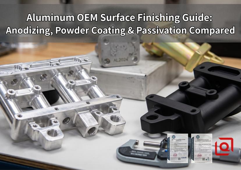
Slap a ±0.005 mm bore tolerance on 6061-T6, then drop a generic “MIL-A-8625 Type III Hardcoat” callout in the corner without calculating pre-plate offsets? You’ve just bought yourself a bucket of scrap. In our shop at Ningbo Liqin, we see it every week—engineers treating anodizing like simple cosmetic spray. It isn't. It's a dimensional shift driven by tank chemistry.
Whether your component lives in salt-drenched sea air or takes a beating on a pick-and-place arm, winging the coating spec will bite you.When spec'ing Type II, hardcoat, powder, or Alodine, you're constantly trading off dielectric barrier and Vickers hardness against fatigue drop, that 50/50 growth-penetration split, and your mill's true holding capability.
Quick Guide: Aluminum Finishing Specs from Our Shop Log
We pulled these hard numbers straight from our CMM inspection data and salt-spray tanks on 6061-T6 and 7075-T651 runs:
| Finishing Route | Film Thickness | Growth / Side | Salt Spray (ASTM B117) | Primary Target |
| Type II Anodize | 8 µm – 25 µm | +50% of film | 336 hrs (sealed) | Color styling & baseline corrosion |
| Type III Hardcoat | 25 µm – 50 µm | +50% of film | 1,000+ hrs | Heavy wear & dielectric strength |
| Chem Film (Alodine) | 0.3 µm – 1.0 µm | Negligible (<0.2 µm) | 168 hrs | EMI shielding & electrical ground |
| TGIC Powder Coat | 60 µm – 110 µm | +60 µm – 110 µm | 1,500+ hrs | Outdoor weather & impact armor |
Anodizing Kinetics: Type II vs. Type III Hardcoat
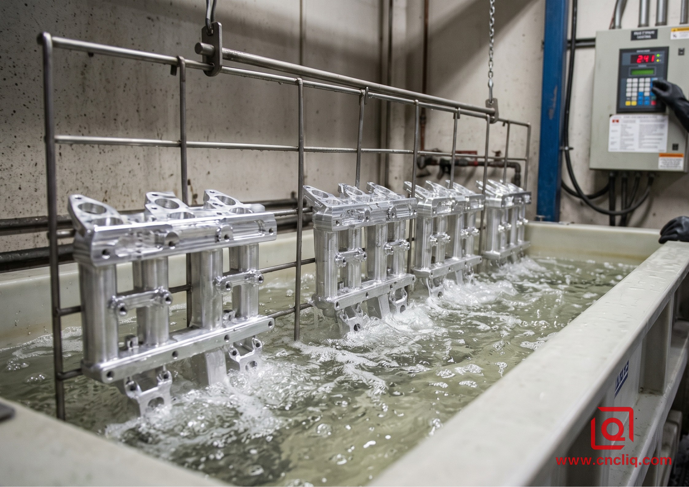
Out on the line, separating standard Type II from Type III hard anodize comes down to three shop-floor dials: tank chill, bath concentration, and rectifier output. To get Type II right without burning parts, we peg the H₂SO₄ mix right at 15% to 18%, hold solution temps between 18°C and 21°C, and dial in a steady 1.2 to 1.5 A/dm². That balance grows an open hexagonal Al₂O₃ structure ready to trap dye. Once the shade looks right, drop the lot into 96°C DI water—that hydrates the alumina into boehmite [AlO(OH)] and seals those micro-pores shut for good.
Type III hardcoat turns the temperature down to -2°C to 4°C, ramps sulfuric acid concentration to 180–200 g/L, and cranks current density up to 2.5–3.6 A/dm² under heavy air agitation. Lower bath temperature retards chemical dissolution of the oxide layer while higher current density accelerates galvanically driven growth.
                          Type III Hardcoat Anodize Growth

       Exterior Boundary (Rougher, porous outer layer)
       ┌──────────────────────────────────────────────────────────┐
       │  o   o   o   o   o   o   o   o   o   o   o   o   o   o  │ ── 50% Growth (Extends beyond raw boundary)
       │  │   │   │   │   │   │   │   │   │   │   │   │   │   │  │
       ├──┼───┼───┼───┼───┼───┼───┼───┼───┼───┼───┼───┼───┼───┼──┤ ── Pre-plating Machined Boundary
       │  │   │   │   │   │   │   │   │   │   │   │   │   │   │  │
       │  o   o   o   o   o   o   o   o   o   o   o   o   o   o  │ ── 50% Penetration (Consumes substrate metal)
       └──────────────────────────────────────────────────────────┘
       Base Aluminum Alloy Substrate (AL6061-T6 / AL7075-T651)
Anodizing doesn't coat parts like paint; it turns raw aluminum into oxide from the inside out. As a rule of thumb on the line, figure half that film stacks outward past your pre-cut line, while the other 50% bites straight back into the parent metal.
Take a practical shop example: say a print calls for a 50 µm Type III hardcoat on a 20.000 mm (+0.010/-0.000 mm) ground pin.
-
Radial build-up per side = 50 µm × 50% = 25 µm (0.025 mm).
-
Total OD growth = 0.025 mm × 2 = 0.050 mm.
-
That leaves you with a finished pin blowing past tolerance to 20.050 mm.
If your machinist turned that pin to 20.005 mm before plating, the component is scrap upon returning from the plating shop. You must offset toolpaths in CAM by 0.025 mm per side on external features and open up internal bores by 0.025 mm per side prior to tank submersion.
Blind Hole Traps & Gas Bubbles
Machining a deep blind pocket or M4×0.7 tapped feature on AL7075-T651 components? Expect acid trap disasters unless you alter racking protocols. During etching inside a 50 g/L NaOH solution at 55°C, micro-bubbles of hydrogen gas cluster inside downward-facing cavity geometries on titanium racks.
                                  Racking Bubble Trap Dynamics

         INCORRECT (Pocket Oriented Downward)        CORRECT (Tilted 30° - 45° Upward)

           Titanium Rack Arm                           Titanium Rack Arm
                 │                                           │
         ┌───────┴───────┐                           ┌───────┴───────┐
         │  Aluminum Part│                           │  Aluminum Part│
         │  ┌─────────┐  │                           │  ╲            │
         │  │H₂ H₂ H₂ │  │ ── Trapped Gas            │   ╲  Gas      │ ── Bubbles escape freely
         │  │Gas Bubble│ │    Blocks Electrolyte     │    ╲ Escapes  │    Full electrolyte contact
         └──┴─────────┴──┘                           └─────╲────────┘
Trapped hydrogen prevents acidic bath solutions from contacting the metal surface. Result: zero anodic layer formation inside cavities, acid bleeding post-rinse, and rapid white corrosion powder blooming inside threads within 48 hours.
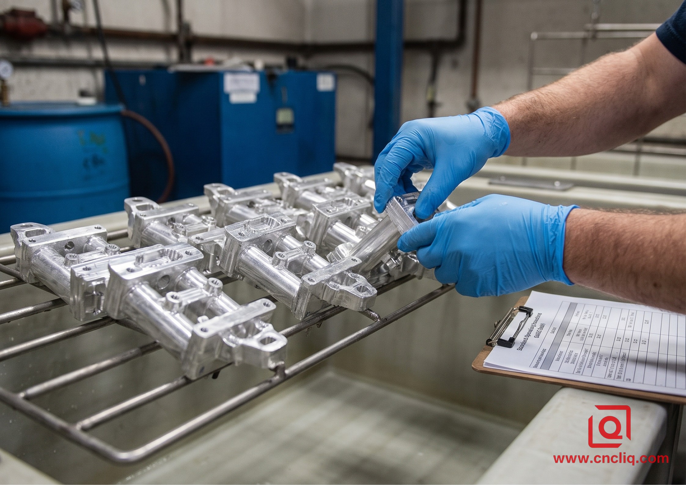
Shop-Floor Mitigation Protocol:
-
Mandate Rack Tilting: Angle all blind cavities upward at 30° to 45° minimum during rack attachment.
-
Specify Drainage Cross-Holes: Add 1.5 mm non-functional relief holes at cavity apexes on CAD models when allowed.
-
Post-Anodize Neutralization: Flush blind tapped holes with a 5% sodium bicarbonate (NaHCO₃) solution before final warm DI water rinsing to neutralize residual H₂SO₄.
Passivation & Chem Film: MIL-DTL-5541 Chromate Conversion
Need chassis grounding or EMI/RFI shielding across your aluminum plate? Rule out anodizing immediately. That grown Al₂O₃ layer acts as a stubborn dielectric insulator—we routinely log breakdown over 500 V at just 25 µm. Instead, spec MIL-DTL-5541 Type II Class 3, utilizing hex-free zirconium/titanium chemistry like SurTec 650.
The tank chemistry works by lightly biting into native Al₂O₃ inside an acidic fluoride bath (hold pH 1.8 to 2.4 at 30°C to 40°C for 60 to 180 seconds). You end up with an amorphous complex oxide skin under 1.0 µm that passes current while holding off corrosion.
                       MIL-DTL-5541 Processing Windows

  Alkaline Clean ──> Acid Deoxidize ──> Chem Film Immersion ──> DI Water Rinse
  (pH 9.5-11.0,     (HNO₃/HF blend,    (pH 1.8-2.4,             (T < 60°C dry,
   60°C, 5 min)      25°C, 2 min)       35°C, 90 sec)            No bake > 65°C)
Hard Rules for the Chem Film Line:
-
Cap Your Bake Temp: Keep parts strictly below 65°C for the first 24 hours. Rush them through a hot cure, and that fresh amorphous gel skin dries out and crazes—we've watched salt-spray ratings plunge from 168 hours straight down to under 24.
-
Hit the Contact Spec: Clearing the MIL-DTL-5541 Class 3 ceiling of 5,000 µΩ per square inch under 200 psi starts in the prep tank. Strip every trace of copper smut off AL2024 or AL7075 during deox, or the lot fails surface resistance before it even ships.
Powder Coating: Managing Layer Buildup on Threads
Baking an AAMA 2604 TGIC polyester powder coat onto 6061-T6 brackets locks down tough UV resistance and sails past a 1,500-hour salt-spray check. But don't overlook the gun: electrostatic spraying lays down heavy skin—easily stacking 60 µm to 110 µm per face.
                           Powder Coat Thread Clearance

          Coating Build (60 - 110 µm thick per wall)
          │
          ▼ ┌─┐     ┌─┐     ┌─┐
         ┌──┘ └───┐ │ └───┐ │ └───┐
         │        └─┘     └─┘     │  ◄── Pitch Diameter closes up if uncapped!
         └────────────────────────┘
          Internal Thread Profile
Leaving internal M6×1.0 threaded features or H7 dowel pin bores unmasked during powder spray causes major assembly failures:
-
Internal thread pitch diameter shrinks by up to 0.220 mm.
-
Fasteners bind solid after two turns, shearing off stainless bolts inside parts during line assembly.
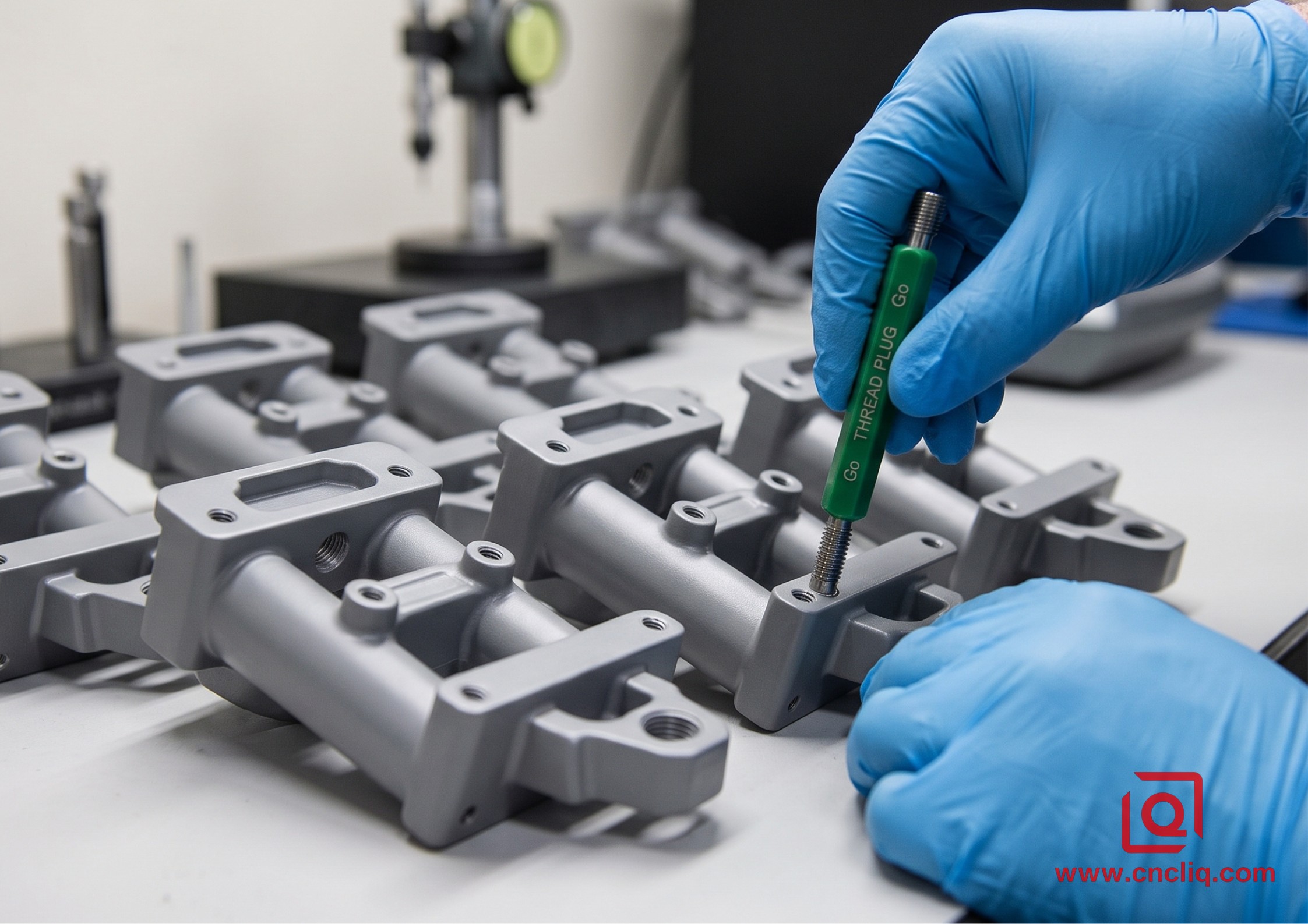
Masking & Thread Preparation Standard:
-
Insert silicone pull plugs rated to 220°C into reamed holes prior to electrostatic application.
-
Cap male studs with silicone sleeves, terminating 1.0 mm clear of shoulder contact faces.
-
If chasing threads post-coating, use 0.1 mm oversize taps (e.g., M6 6G oversize) to clean out thermal overspray without stripping base aluminum threads.
Alloy Selection Impacts on Surface Quality
Never mix aluminum alloys in the same anodizing tank run. Alloy composition radically alters electrochemical anodic oxidation kinetics:
                            Alloy Anodizing Kinetics

   AL6061-T6   ─── [Mg-Si Matrix]  ───> Uniform, Clear, Dense Oxide (Ideal)
   AL7075-T651 ─── [High Zn (5.6%)] ───> Yellow/Olive Tint, High Microhardness
   AL2024-T3   ─── [High Cu (4.4%)] ───> Intermetallic Burning, Porous Structure
-
AL6061-T6: High Mg-Si matrix (Mg 1.0%, Si 0.6%). Anodizes cleanly. Produces dense, clear or black dyed layers with low micro-fissuring.
-
AL7075-T651: High zinc content (5.6% Zn, 2.5% Mg). Yields dense hardcoat layers, but displays a natural olive tint in un-dyed Type III finishes. Requires strict bath temperature control at 0°C to avoid soft outer layers.
-
2024-T3 Alloys (4.4% Cu): That heavy copper load spells trouble in an acid bath. Those Cu-rich phases leach out fast, creating nasty hot spots that scorch workpieces instantly. Don't blast it with full juice upfront—ease the current density up toward 2.0 A/dm² on a steady ramp, and never push depth beyond 35 µm unless you want pitted scrap.
Quality Inspection Protocols & Metrology Standards
Verify OEM aluminum components post-treatment against engineering drawings using three mandatory metrology tools:
                          Shop-Floor Inspection Flow

   ┌──────────────────────┐    ┌──────────────────────┐    ┌──────────────────────┐
   │ Eddy-Current Gauge   │ ──>│ Optical Profilometer │ ──>│ Cross-Hatch Tape     │
   │ (ISO 2360 / ASTM B244)│    │ (ISO 4287 / ASME B46)│    │ (ASTM D3359 Method B)│
   └──────────────────────┘    └──────────────────────┘    └──────────────────────┘
     Film Thickness Check        Surface Roughness (Ra)      Paint / Coating Adhesion
- Eddy-Current Checks (ISO 2360 / ASTM B244): Always null out your pen on an untreated 6061 block prior to checking batches. Spot-check five distinct locations per side—you're making sure that hard anodize lands squarely in the print window (e.g., 40 µm ± 5 µm).
- Surface Profilometry (ISO 4287 / ASME B46.1): Drag the stylus across sealing lands. Because oxide growth roughs up raw surfaces as cells form, always double-check post-treatment Ra against gland limits—keep static O-ring seats under Ra 0.8 µm.
- Cross-Hatch Adhesion (ASTM D3359 Method B): Scribe a 1 mm 6x6 grid straight into the powder coat. Lay down 3M 610 or Permacel 99 tape, yank it back clean at 180°, and inspect the squares. You want zero flaking—solid 5B pass.
- Final DFM Checklist for OEM Aluminum Surface Finishing
Offset CAM Toolpaths: Apply -50% film thickness radial offset on external CNC turned/milled surfaces for Type II/III anodizing.
Specify Post-Plating Dimensions: Write "Dimensions apply AFTER surface treatment per MIL-A-8625" on 2D prints to hold suppliers accountable.
Eliminate Trapped Gas Geometry: Add 1.5 mm relief holes or tilt part geometry on racks to prevent hydrogen bubbles in blind holes.
Select Chem Film for Grounding: Specify MIL-DTL-5541 Type II Class 3 on chassis faces requiring electrical continuity under 5,000 µΩ.
Do Not Bake Chem Film Hot: Keep drying temperatures below 65°C to preserve corrosion-resistant hydrated gel layers.
Mask Precision Bores Before Powder Coating: Use 220°C silicone plugs on all threaded holes and bearing seats prior to electrostatic TGIC spraying.
FAQs
Q1: How should I call out drawing tolerances on CNC prints if parts undergo 50 µm Type III hardcoat?
A: Always add a clear title block note: "All dimensions apply AFTER surface treatment per MIL-A-8625 Type III." On the shop floor, CAM programmers must subtract 50% of the target coating thickness (0.025 mm per side for a 50 µm build) from external profiles and expand internal bores by 0.025 mm per side prior to tank submersion.
Q2: Can we achieve both anodized wear protection and electrical grounding on the same aluminum OEM chassis?
A: Yes, via dual-finish selective masking. Dip your bare part in a MIL-DTL-5541 Type II Class 3 chem-film tank first. Next, slap die-cut vinyl dots or Kapton tape over your grounding pads, then dunk the whole housing into the Type II or Type III hardcoat line. Once you peel that masking, you get untouched conductive pads clocking well below 5,000 µΩ contact resistance—while the rest of the shell takes on tough, non-conductive armor.
Q3: Why do clear-anodized AL7075 and AL6061 components show obvious color mismatch in the same assembly?
A: Alloy chemistry dictates base tint. Thanks to its balanced Mg-Si recipe, 6061 builds a clean, crisp oxide layer. Run 7075 through that exact same hardcoat tank, though, and its 5.6% zinc content turns raw Type III coatings a funky olive-yellow. When you're bolting mixed-alloy parts side-by-side and need an exact visual match, skip the clear finish. Call out a #120 glass bead blast paired with a rich Class 2 black dye instead.
Q4: At what thread size is silicone plug masking mandatory during powder coating?
A: Plug any internal thread M8 or smaller without exception. TGIC powder builds 60 µm to 110 µm per wall, choking pitch diameters by over 0.20 mm and binding fasteners instantly. For M10 and larger, you can occasionally chase threads with an oversized 6G tap post-cure, but pre-plugging with 220°C tapered silicone plugs avoids chipping the painted edge around the hole chamfer.
Q5: Why did our AL2024 components pit and burn during Type III hardcoat anodizing?
A: AL2024 contains roughly 4.4% copper. Crank up the rectifiers on 2024 hardcoat, and those copper phases eat away way faster than your raw aluminum—sparking micro-arcing and instant thermal blowout. To keep parts from burning, hold your build under 35 µm, ramp current density slowly up toward 2.0 A/dm² on a pulse profile, and lock bath chillers flat at 0°C.
Summary
Getting precision aluminum parts right means treating your finishing line like another CNC pass, not an afterthought paint booth. Compensate for that 50/50 Type III hardcoat growth in your CAM file, mask threads before heavy TGIC powder flies, and keep your chem-film dry-off temps low. Do that, and your parts pass QA on the first try. Once you respect how specific alloys behave in the tanks—from predictable 6061 to burn-prone 2024 copper phases—you stop burning lead time on bench rework and scrapped lots.
Contact Information
Disclaimer
All technical articles, material specifications, machining recommendations, and surface treatment details published on this blog are for informational and reference purposes only. Please note that general blog insights do not replace signed technical agreements. Because custom parts vary by material heat numbers, machine calibrations, and specific tolerances, binding quality specs are governed solely by your approved CAD drawings, signed contracts, and formal quality plans.
All customer case studies featured on this blog have been thoroughly anonymized and sanitized. The performance metrics, manufacturing workflows, and imagery displayed serve solely to demonstrate our custom machining capabilities and do not represent a single universal standard for all orders.
Liqin Manufacturing Team
Built on 18 years of precision engineering experience, Ningbo Liqin Industry manufactures high-tolerance metal components for demanding global markets. We operate out of a 6,500 m² production hub equipped with over 150 machines, running 4-axis and 5-axis CNC machining, mill-turn machining, cold extrusion, and pressure die casting under one roof. This setup allows us to manage projects seamlessly, taking parts from initial CAD concepts directly to finalized shipments.
We handle quality control with zero compromise. We treat tight tolerances with the engineering discipline they require. Backed by ISO 9001, ISO 13485, and IATF 16949 certifications, our QA engineers run strict IPQC, FQC, and OQC checks on every single production batch. From CMM dimensional mapping and optical profiling to hardness and salt-spray testing, we validate your critical specs upfront—so you receive drop-in ready components with zero assembly headaches or costly line stoppages. On top of manufacturing, you can rely on us for two-hour response times on new RFQs, direct support for prototype sampling, and smooth export shipping across Europe, North America, Asia, and Oceania.
Welcome your inquiries and samples. Visit our website or contact us directly for a competitive quote!
