 English




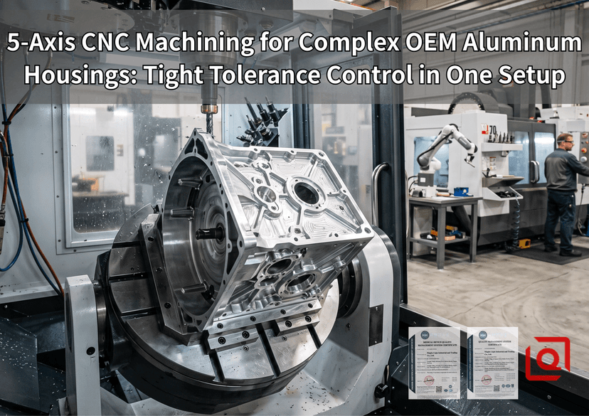
If you’re running OEM aluminum housings with intersecting fluid channels, 0.008 mm bore alignments, and complex O-ring seal grooves, continuous 5-axis machining isn’t a premium flex. It’s a survival requirement.
The Shop-Floor Reality: Thermal Drift, Elastic Recovery, and Datum Inflation
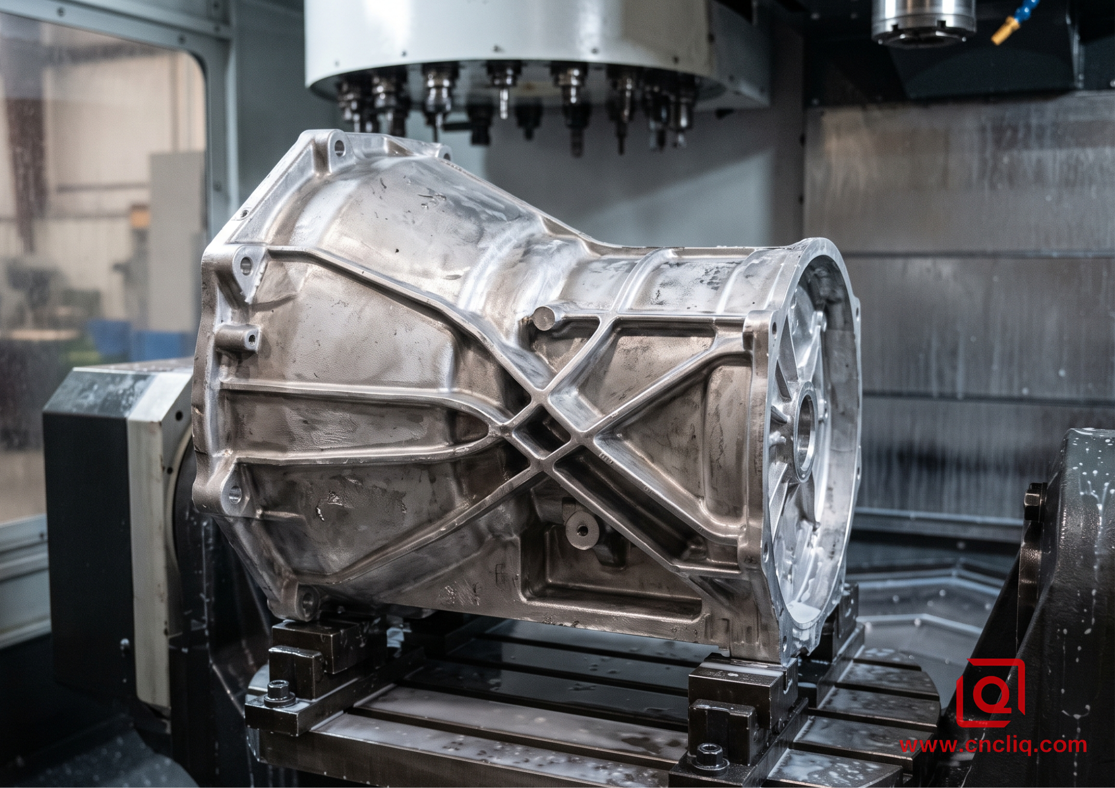
When hogging out 78% of a solid 7075-T651 billet down to a 2.4 mm nominal wall housing, internal stress release is your primary enemy. T651 temper reduces residual stress through controlled stretching, yet asymmetric stock removal still unleashes non-uniform elastic relaxation.
Take a typical 220mm × 180mm × 110mm power-transmission housing. On a 3-axis rig, flipping the part three times compounds stack-up tolerances. Every re-clamping introduces contamination particles—even a 15-micron aluminum chip under a locator pin tilts the Z-axis vector by 0.012° over a 150mm span. By the time you reach the third setup to hit a 30° cross-hole, your positional tolerance to ISO 2768-mK is completely shot.
[3-Axis Multi-Setup]
Setup 1 (Face A) ➔ Flip/Re-clamp ➔ Setup 2 (Face B: +12μm tilt) ➔ Flip/Re-clamp ➔ Setup 3 (Angle Bore: Accumulative Error >0.035mm) ❌ SCRAP

[Simultaneous 5-Axis Single Setup]
Raw Billet ➔ Single Pneumatic Clamp ➔ Probe Calibration ➔ Rough & Finish 5-Axis Tool Paths ➔ CMM In-Situ Verification (Runout <0.005mm) ✅ PASSED
Thermal management is equally ruthless. Spindle growth at 18,000 RPM on an HSK-A63 arbor expands the tool point by up to 14 microns over a 45-minute hogging cycle if thermal stabilization loops are skipped. Worse, pouring flood coolant at 20°C onto an aluminum workpiece heated to 62°C via heavy roughing causes instantaneous localized thermal shock, shrinking the internal pocket width by 0.022 mm mid-pass.
Single-Setup Machining Protocol for Complex Housings
Step 1: Hydro-Pneumatic Fixturing and Clamping Force Vectoring
Standard vise jaws deform thin walls. Period.
-
Use zero-point clamping receivers embedded directly into a 5-axis trunnion table (A/C axis).
-
Interface via custom aluminum risers bolted to sacrificial mounting lugs on the billet base.
-
Set hydraulic clamping pressure to exactly 1.8 MPa. Exceeding 2.2 MPa yields a localized 0.006 mm permanent elastic distortion across the main stator bore.
-
Torque fixture studs in a star pattern to 45 Nm.
Step 2: Adaptive In-Situ Probing and Dynamic Datum Alignment
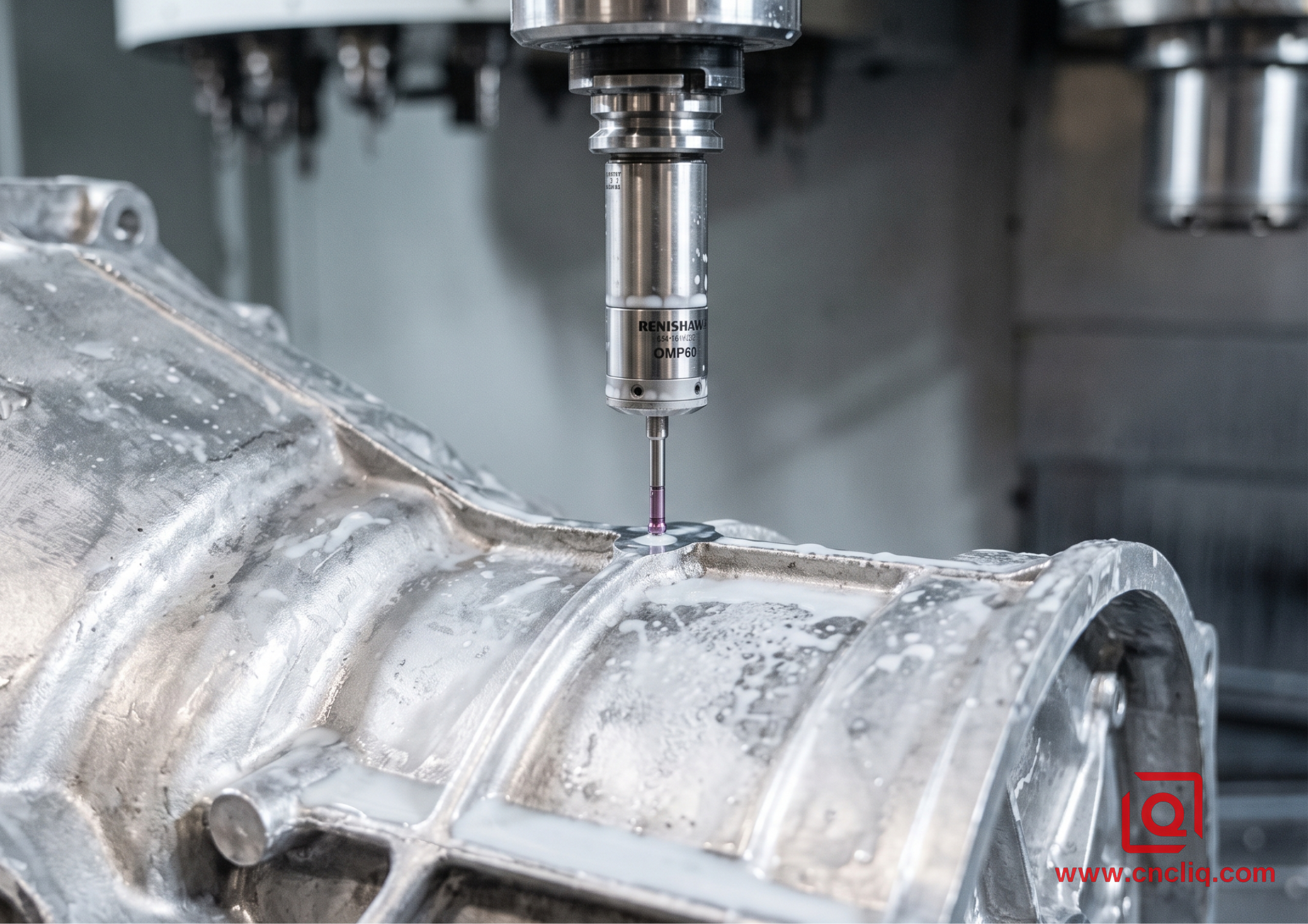
Forget setting mechanical stops.
-
Load a Renishaw OMP60 strain-gauge probe.
-
Execute a 9-point surface scan across raw casting datum pads.
-
Call Siemens 840D
CYCLE800or HeidenhainPLANE SPATIALto rotate the working plane dynamically. -
Establish the spatial origin based on actual stock geometry rather than theoretical CAD zero. This compensates for raw billet bow up to 0.35 mm without manual shimming.
M126 ; Enable shortest path traverse for rotary axes
G68.2 X0 Y0 Z0 A30.0 C45.0 ; Spatial plane rotation
G05.1 Q1 HPCC mode active ; High-precision contour control
Step 3: High-Feed Roughing (HFR) with Volumetric Chip Load Control
Do not plunge a standard endmill into a deep pocket cavity.
-
Tool: 16mm 3-flute uncoated carbide endmill, 45° helix, balanced to G2.5 at 24,000 RPM.
-
Cutting Parameters:
-
Spindle Speed (n): 16,500 RPM
-
Cutting Speed (Vc): 829 m/min
-
Feed per Tooth (fz): 0.18 mm/tooth
-
Axial Depth of Cut (ap: 12.0 mm (Dynamic Trochoidal Milling)
-
Radial Depth of Cut (ae): 1.2 mm (10% engagement)
-
-
Strategy: Trochoidal toolpaths maintain a constant chip thickness (h{max} = 0.045mm). This ensures 82% of the generated friction heat exits with the flying chip, keeping workpiece core temperature under 34°C.
Step 4: 5-Axis Impeller & Internal Channel Finishing
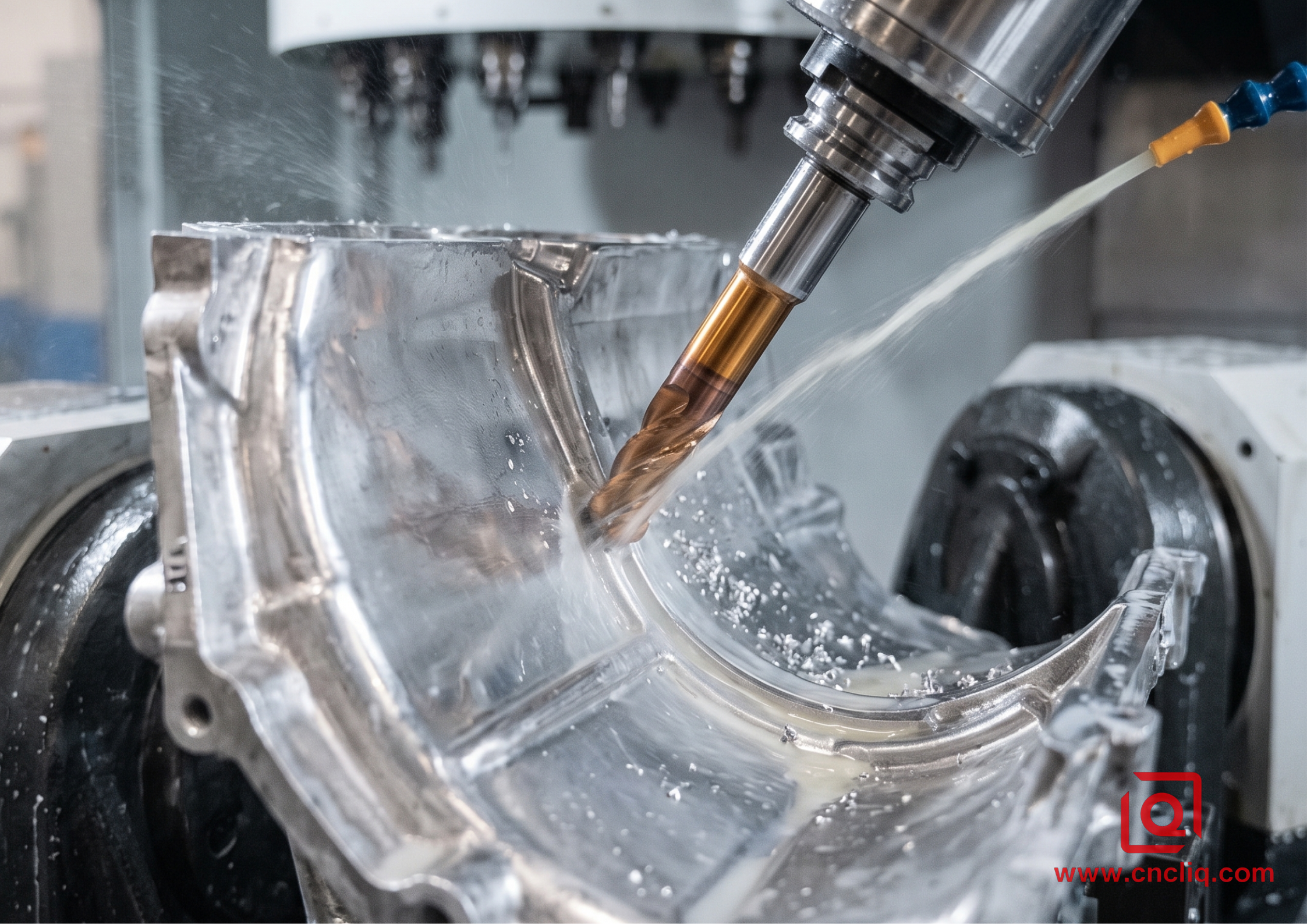
To hit a Ra 0.8 µm surface finish on deep internal cavities without chatter:
-
Deploy a 6mm taper ball-nose cutter with a 75mm gauge length.
-
Maintain a constant lead angle of 15° and tilt angle of 10° relative to the surface normal vector.
-
Never cut with the zero-surface-velocity center point of a ball-nose tool.
-
Stepover (af): 0.15 mm for smooth scallop height calculation (h≤ 0.0008mm).
-
Engage high-pressure through-spindle coolant (70 bar) utilizing a 6% semi-synthetic water-soluble oil emulsion to clear chips instantly from deep blind holes.
Process Data & Metric Matrix
| Parameter / Metric | Standard 3-Axis Process | Continuous 5-Axis Process (Single Setup) | Standard / Target |
| Setups Required | 4 to 6 Setups | 1 Setup | Process Optimization |
| Concentricity (Bore-to-Bore) | 0.025 mm – 0.040 mm | 0.006 mm | ISO 1101 |
| Position Tolerance | 0.030 mm | 0.008 mm | True Position ∅ 0.010 |
| Surface Roughness ($Ra$) | Ra 1.6μm - 3.2μm | Ra 0.6μm - 0.8μm | DIN EN ISO 4287 |
| Thermal Expansion Drift | Uncompensated (≈ 0.020 mm) | In-situ probe real-time dynamic compensation | △ T < 2℃ |
| Cycle Time per Housing | 114 minutes | 42 minutes | -63% Reduction |
In-Situ Quality Control & Final Verification
Don't wait until the CMM room flags out-of-round bores two shifts later.
Before unclamp, run an automated internal bore inspection macro using a spindle-mounted probe at 20°C ambient calibrated temperature:
-
Measure 16 points along the inner cylinder wall of the main bearing journal at two Z-depths (Z -10mm and Z -45mm).
-
Calculate cylindricity via Least Squares Zone (LSZ) algorithms directly on the CNC controller.
-
If cylindricity exceeds 0.005 mm, trigger an automatic micro-finishing spring pass with a 0.002 mm stock offset adjustment.
Inspect the O-ring face flatness using laser scanning on the 5-axis table; ensure total indicator reading (TIR) remains under 0.009 mm across the entire 180mm flange diameter.
By eliminating setup changes, controlling clamping vectors, and maintaining rigid thermal protocols, you lock in micro-level tolerances on complex OEM aluminum housings—consistently, predictably, and profitably.
FAQs
Q1: Why do you specify 1.8 MPa hydraulic clamping pressure instead of mechanical manual clamping for thin-walled OEM housings?
Answer: Manual clamping via standard torque wrenches introduces uncontrolled asymmetrical stress vectors. A typical manual vise delivers inconsistent localized pressures ranging from 12 kN to 35 kN, which forces a 2.4 mm aluminum wall beyond its yield point, leaving a residual 0.012 mm – 0.025 mm permanent geometric distortion post-unclamp. By integrating zero-point hydro-pneumatic receivers calibrated strictly to 1.8 MPa (±0.05 MPa) with custom aluminum contact pads, we distribute clamping force uniformly along non-critical structural webs. This keeps localized elastic strain under 45με, guaranteeing that precision bores remain round within 0.005 mm once released.
Q2: How do you prevent 7075-T651 aluminum housings from warping after removing 75%+ of raw billet volume?
Answer: While 7075-T651 is stress-relieved via mechanical stretching (1.5% - 3% permanent set), aggressive asymmetric stock removal still unbalances internal stress fields. We combat this using a three-tier mitigation protocol:
-
Dynamic Trochoidal High-Feed Roughing (HFR): Maintaining a constant radial engagement (ae = 10%D) to limit heat transfer into the core (≤34℃).
-
Intermediate Stress-Relief Soak: For ultra-precise aerospace housings, we pause after roughing and execute a controlled thermal cycle at 180°C for 2 hours (or allow 24-hour ambient stress relaxation) prior to semi-finishing.
-
Symmetrical Roughing Passes: Equalizing material removal depth across opposing faces to maintain balanced residual tension profiles before final finishing.
Q3: What is the benefit of using CYCLE800 spatial plane rotation over physical angled fixtures for multi-axis cross-bores?
Answer: Physical angled sine plates or dedicated oblique fixtures introduce mechanical stack-up errors—each interface adds approximately 0.008 mm position error and 0.005° angular tilt. Using Siemens CYCLE800 (or Heidenhain PLANE SPATIAL), the CNC controller calculates real-time kinematic transformations (X-Y-Z-A-C) directly within the 32-bit trajectory generator. Coupled with an in-situ strain-gauge probe (Renishaw OMP60) taking 9 reference points on raw casting pads, we dynamically re-align the coordinate system to match actual part geometry. This eliminates fixture build cost while keeping compound cross-hole positional accuracy under ∅ 0.008 mm to Datum A.
Q4: Why is Type III Hard Anodizing thickness crucial during the pre-machining tolerance calculation for H7 hole fits?
Answer: Type III Hardcoat Anodizing (MIL-A-8625 / ISO 10074) builds a oxide layer that grows 50% inward into the aluminum substrate and 50% outward from the surface. If your drawing calls for a 25.000mm +0.021/+0.000 mm (H7) pin bore and a specified 40μm±5μm hard anodize coating, the internal diameter will shrink by 40μm (20μm outward growth per side). Without pre-machining offset, your finished bore chokes to 24.960mm, completely seizing the locating pin. We pre-calculate tool paths with an explicit +0.040mm oversize offset on critical features prior to sending parts to the plating bath.
Q5: How do you eliminate chatter marks on deep internal cavities when utilizing long tool overhangs (L/D > 8)?
Answer: When machining deep internal pump cavities with tool gauge lengths exceeding 8 times the diameter, standard solid carbide tools experience harmonic resonance and deflection. We deploy three specific countermeasures:
-
Heavy Metal / Carbide Anti-Vibration Extensions: Utilizing high-density tungsten-alloy shanks to damp vibration amplitudes by up to 70%.
-
Variable Helix & Asymmetrical Flute Geometry: Disrupted flute spacing breaks up regenerative chatter frequencies.
-
Tilted 5-Axis Tool Paths: Maintaining a continuous 15° lead / 10° tilt angle ensures the cutting force vector pushes axially into the spindle bearings rather than radially against the thin workpiece wall.
Summary
Continuous 5-axis single-setup machining eliminates datum transfer errors, controls thin-wall elastic strain under strict 1.8 MPa hydraulic clamping, and suppresses thermal drift using trochoidal high-feed paths with in-situ probe compensation. By maintaining tight control over processing parameters and plating allowances, complex OEM aluminum housings can consistently achieve micro-level precision.
Ready to optimize your next manufacturing run? Send us your CAD files to receive a free DFM analysis and an actionable, cost-saving OEM quote from our engineering team within 24 hours.
Contact Information
Disclaimer
Liqin Manufacturing Team
We are Ningbo Liqin Industrial & Trading Co., Ltd.,a professional manufacturer with over 18 years of experience in high-precision custom metal parts. We specialize in CNC machining, forging, die casting, and cold extrusion processes, serving industries such as automotive, medical, aerospace, electronics, and more. Our factory covers an area of 6,500 square meters and is equipped with 150+ advanced machines, including:
- CNC machining centers (4-axis, 5-axis)
- CNC lathes and turning-milling complexes
- Cold extrusion equipment (250T–650T)
- Die casting machines
We adhere to ISO9001, ISO13485: 2016, and IATF16949: 2016 standards, implementing end-to-end quality management: In-process quality control (IPQC), final quality control (FQC), outgoing quality control (OQC). CMM, projectors, hardness testers, and salt spray test equipment. Our products are exported to North America, Europe, Asia, and Oceania. We offer:
- One-stop service from design to delivery
- Quick response within 2 hours for quotes and technical support
- Custom solutions based on your drawings or samples
Welcome your inquiries and samples. Visit our website or contact us directly for a competitive quote!
