 English




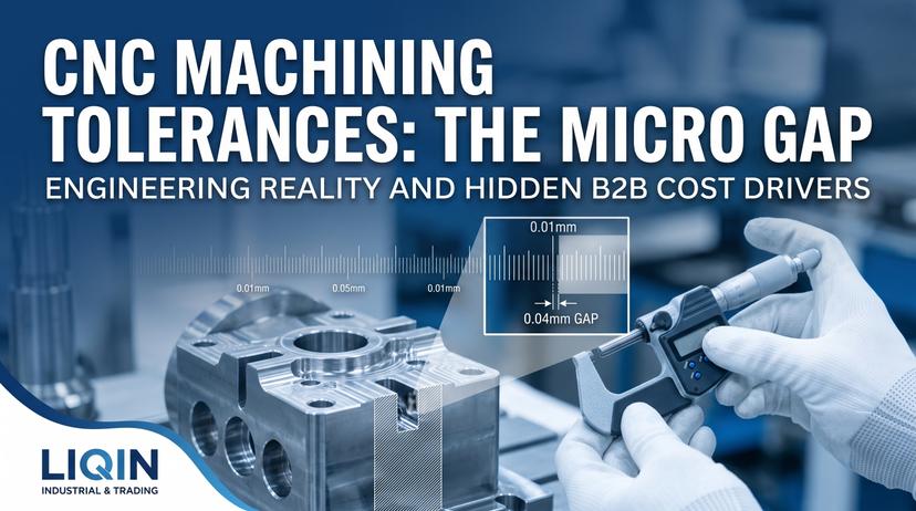
In precision CNC machining, setting a tolerance is never just about getting a mechanical fit right; it is a critical business choice that directly impacts your R&D timeline and purchasing budget. The moment you tighten your drawing tolerance from a standard ±0.05mm to an ultra-precise ±0.01mm you trigger a massive cost spike on the shop floor, as every micron you shave off ripples through the entire manufacturing process.
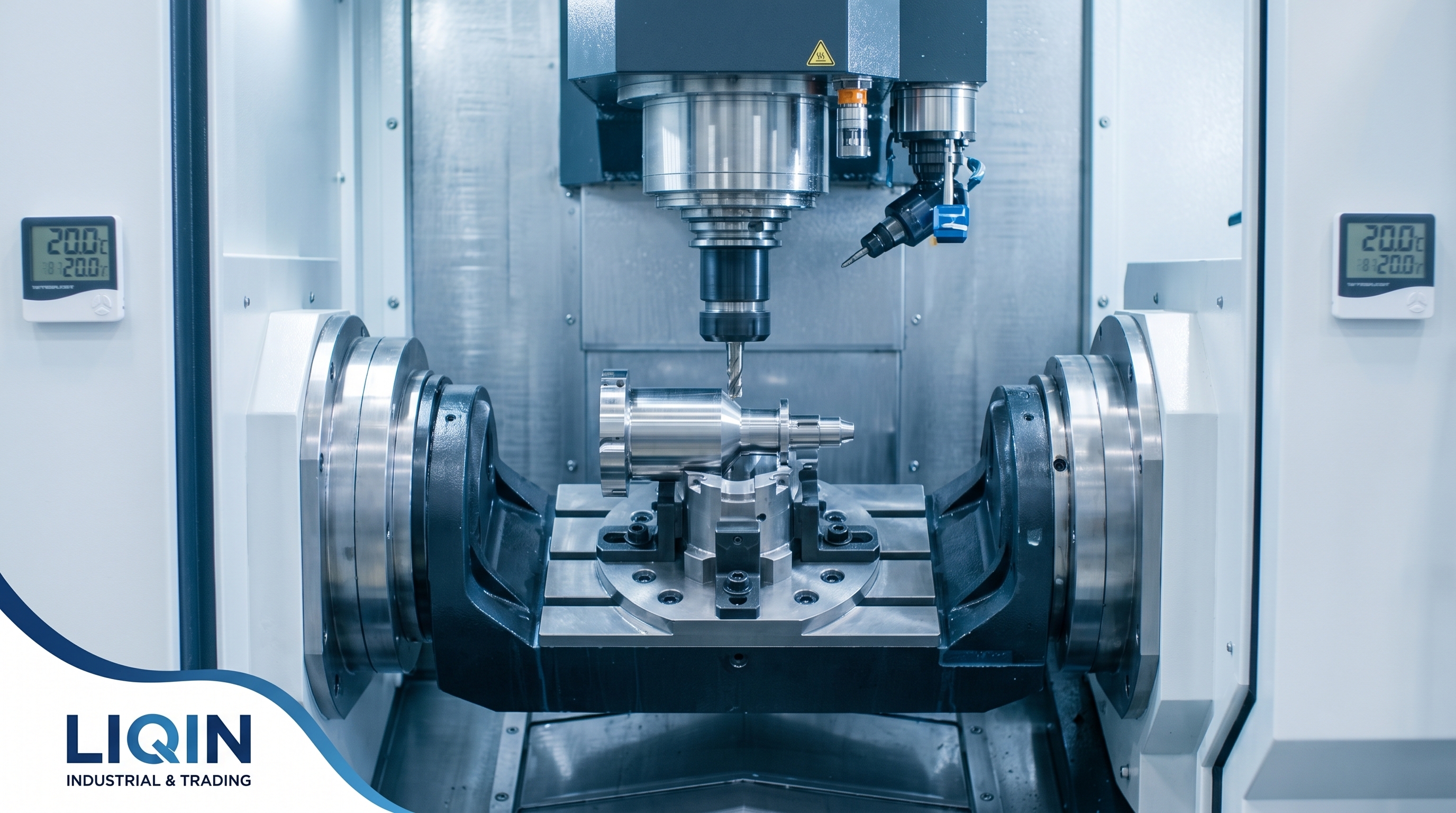
To hit that mark, you have to upgrade to high-end multi-axis machining centers, switch to custom high-rigidity fixtures with ultra-low thermal expansion, and even run inspections in climate-controlled rooms to fight off temperature drift. Drawing from years of front-line manufacturing experience at Ningbo Liqin Industrial & Trading Co., Ltd., this guide breaks down how such a tiny accuracy gain forces a complete process overhaul, and why this seemingly minor $0.04\text{ mm}$ difference triggers an explosive, non-linear cost hike.
Table: CNC Machining Tolerance, Difficulty and Cost Coefficient
| Tolerance Class | Nominal Tolerance Range | Core Equipment and Environment | Cost Coefficient |
| Standard |
±0.1mm - ±0.2mm |
Standard 3/4-axis CNC mills; standard workshop |
Baseline (1.0x)
|
| Precision |
±0.02mm - ±0.05mm |
Mid-to-high-end vertical machining centers |
1.5x - 2.0x
|
| Ultra-Precision |
±0.005mm - ±0.01mm |
Imported 5-axis CNC/mill-turn; climate-controlled workshop |
3.5x - 5.5x |
Why Choose Our Guide? Real Shop Floor Experience from Liqin Industrial & Trading
The industry data and manufacturing logic disclosed in this guide are derived from real-world data accumulated through design reviews and workshop assembly processes at Liqin Industrial & Trading Co., Ltd. As an integrated manufacturing and trading high-tech enterprise deeply serving global industrial automation, Precision Automotive Components, Food-Grade Precision Components, and medical device precision components, we help global R&D teams perform Design for Manufacturability (DFM) reviews every day.
We firmly believe that excellent design does not chase "extreme precision" for its own sake, but rather pursues "the perfect balance of functional realization and cost-efficiency." We always scan every tolerance marking the second a new 3D CAD file lands on our desk. That’s our Liqin engineering team’s standard workflow. Next up, I’ll walk you through all precision machining core details — plain shop talk, no vague jargon, all solid technical logic.
The Physical Nature of Tolerance and the Uncertainty of Mechanical Manufacturing
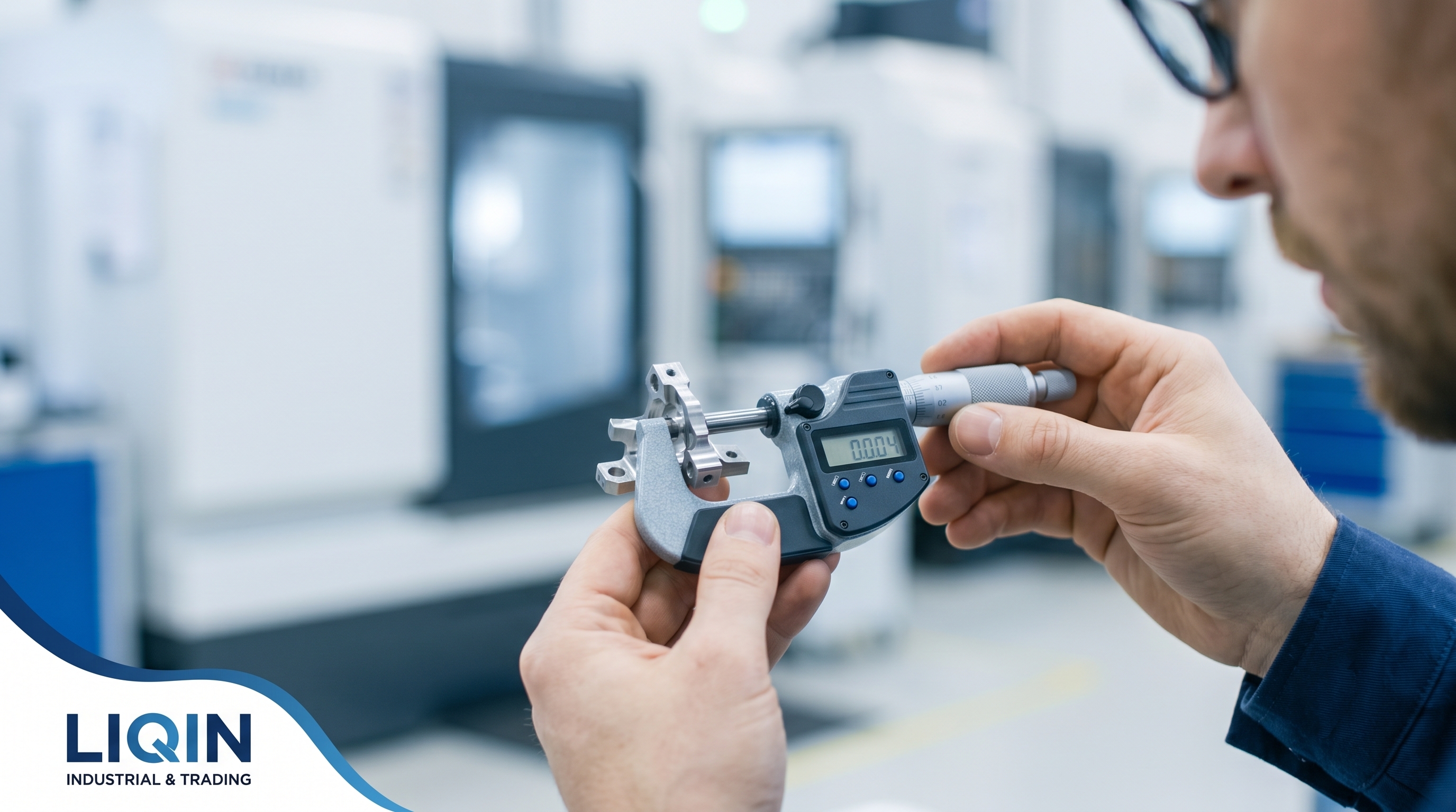
Zero geometric error is impossible in real manufacturing. No matter how high a machine's repeatability is, the final dimensions of a part in actual machining are inevitably affected by the following physical factors:
-
Thermal Stress and Environmental Fluctuations: The cutting zone instantly generates temperatures of several hundred degrees Celsius during cutting due to intense friction, causing micro-expansion of both the tool and workpiece. Even a minor 2°C fluctuation in workshop temperature can cause micron-level dimensional changes in metal raw materials (thermal expansion and contraction).
-
Machine built-in runout issues: Even heavy-duty high-rpm spindles spinning at tens of thousands RPM still carry tiny radial wobble. Add ball screw backlash and subtle rail slide creep, dimensional deviation is unavoidable.
-
Tool edge abrasion is inevitable: Machining tough stock like 304, 316 stainless steel or titanium alloy for hours straight wears cutting edges down permanently. The worn cutter removes less material than programmed, pushing part dimensions over tolerance upper limits.
Therefore, tolerances are not barriers to manufacturing. Instead, they represent a safety margin defined for manufacturing deviations to ensure that "parts can be assembled, fit together, do not leak fluid, and do not vibrate."
Four Core Process Factors Driving Costs in Ultra-Precision Machining
1. Full Upgrade of Machinery and Environmental Conditions
For ±0.05 mm tolerance jobs, regular equipment works perfectly fine. A well-kept 3-axis or 4-axis CNC mill, or a standard high-speed CNC lathe, can run stable batch production in ordinary non-temperature-controlled workshops. We get high yields, low equipment depreciation, and fast daily throughput with zero extra overhead.
On top of equipment upgrades, these precision machines cannot run in ordinary workshops. They require dedicated production zones with strict constant temperature, fixed humidity, and professional vibration isolation treatment. All these hardware and environment upgrades bring massive fixed-cost investment.
2. Strict Tool Control and Frequent Proactive Replacement
When cutting high-hardness raw metals, tool edges continuously shed trace atoms, causing dimensions to drift toward "under-cutting." Under a ±0.05 mm tolerance, normal tool wear can be managed by operators manually making micro-adjustments every few hours.
In ±0.01 mm machining, however, even a 10-micron tool wear directly leads to out-of-tolerance parts. To maintain high yields, the machining system must utilize high-end cutting parameters, utilize in-machine laser tool setters, and implement high-frequency "proactive tool replacement strategies." This reduces tool life utilization by more than 60%, sending tooling consumption costs skyrocketing.
3. DFM Positioning Systems and Physical Clamping Deformation
All metal workpieces produce elastic deformation under clamping pressure. After unclamping, elastic rebound changes part dimensions. This tiny deformation is negligible for ±0.05 mm tolerance but fatal for ±0.01 mm ultra-precision standards.
4. Extended Inspection and Temperature Stabilization Processes
Ultra-precision parts are difficult to measure accurately. Ordinary vernier calipers and micrometers are easily affected by manual operation and temperature, failing ±0.01 mm precision detection.
Liqin Industrial & Trading Classic DFM Optimization Case Study: A Scientific 42% Cost Reduction
-
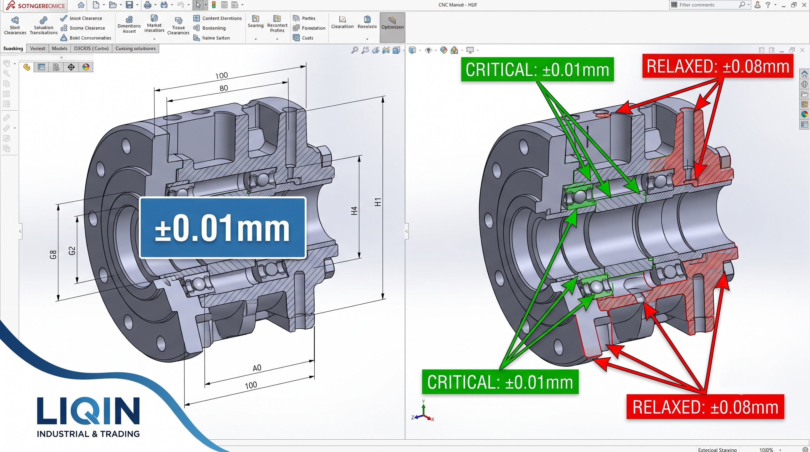
Client Background: A long-term global European packaging machinery multinational sent us a drawing for a transmission bracket made of 316 stainless steel, with an initial purchase order of 800 pieces. Because the client’s R&D engineers were chasing a flawless assembly fit, the entire outer profile, edge thicknesses, deep slots, and assembly mounting holes were uniformly labeled with an extremely high precision of ±0.01 mm.
-
Analysis & Hurdles: Once we received the client’s 3D and 2D drawings, our Liqin DFM engineering team immediately completed process feasibility evaluation. 316 stainless steel is notoriously difficult to machine. It features high internal stress and strong thermal deformation tendency.
If we followed the original full-part ±0.01 mm tolerance requirement, we would be forced to manufacture almost every surface through slow grinding and low-speed wire EDM. Scrap rates would surge, and unit costs would become commercially unviable. -
Tailored Solution: We delivered a targeted localized functional tolerance optimization proposal during our online technical meeting with the client:
We reserved the strict ±0.01 mm interference tolerance only for the core central bearing bore, which fits imported precision rolling bearings. This critical hole is finished via ultra-precision boring and fine grinding to guarantee assembly accuracy and rotational stability.All non-critical features — outer profiles, contact surfaces, side gaps, and bolt clearance holes — were reasonably relaxed to ±0.08 mm. -
Project Benefits: The client fully approved our DFM optimization plan. The original cumbersome process — repeated stress relief + full-scale slow grinding — was replaced with efficient CNC milling plus localized precision finishing.
This upgrade brought tangible results: single-piece cost reduced by 42%, lead time shortened from 15 days to 10 days, while the mechanical performance and assembly precision remained fully unchanged. This project also strengthened our long-term technical cooperation with the client.
FAQs
Q1: Why do material physical and chemical properties directly affect tight-tolerance machining costs?
A: It all comes down to real-world machinability and thermal stability. Tough, sticky alloys like 316 stainless steel and titanium generate massive cutting heat during processing. They harden quickly and build up thermal stress easily. This accelerates tool wear significantly, forcing us to adopt strict, costly process controls just to hold ±0.01 mm precision.
Q2: How to guarantee high-precision rotational fits without excessive cost?
A: Stick to standard hole-basis or shaft-basis fit systems. You do not need ultra-tight tolerances on both mating parts.
Q3: How does Liqin handle dimensions with no tolerance marked on drawings?
A: Undimensioned tolerances follow unified international standards. At Liqin, we strictly apply ISO 2768-m medium tolerance class. Most unmarked dimensions fall within ±0.1 mm to ±0.2 mm deviation.
Q4: What physical conflicts occur between high-precision tolerances and subsequent surface treatments (such as anodizing, chemical passivation, or Teflon coating)?
A: This is a very common design pitfall. All surface coatings alter part dimensions.
Aluminum anodizing adds 5–15 μm thickness per side. Passivation, chemical plating, and Teflon coating also create measurable dimensional changes. If you machine parts dead on ±0.01 mm before treatment, the final size will definitely go out of tolerance after coating.
Q5: How to maximize cost savings via Liqin’s technical support without sacrificing part performance?
A: The most efficient solution is early supplier involvement (ESI).
Send over your STEP/STP 3D CAD files plus tolerance and assembly specs. Our engineering crew will deliver a full DFM review, tolerance adjustment advice and competitive quotation in under 24 hours.
You can quickly check if your design works, cut unnecessary ultra-tight tolerance costs and make the most of your purchasing budget.
Contact Information
Intellectual Property and Technical Specification Disclaimer
-
Design Confidentiality & IP Protection: Liqin strictly protects all client design data and intellectual property. All submitted 3D files, 2D drawings and technical specs remain fully confidential. We will never disclose, share or reuse your designs without your written approval. We also support formal NDA signing per client request.
-
Precedence of Technical Drawings: In case of any inconsistency in dimensions, tolerances or technical requirements between 3D models and 2D drawings during quotation and production, annotations on 2D engineering drawings shall prevail, unless otherwise agreed in writing by both parties.
-
Standard Applicability: All machining cases, tolerance benchmarks and lead-time data on this page serve only for general technical reference. Actual manufacturability and precision performance are subject to the part’s unique structure, material properties and surface treatment processes.