 English




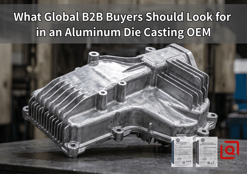
Let us cut past the glossy marketing brochures and corporate videos. When you source custom aluminum die casting components overseas, the real production risks never show up on a homepage slide deck. They sit right inside subsurface blowholes, uneven heat across multi-cavity tools, jumpy shot speeds, and poor mold steel work that wears out ejector pins after just a few thousand shots.
If a supplier eyeballs your 2D prints and instantly guarantees tight callouts without asking about annual run rates, parting line setups, core pulls, or mating face flatness, walk. Practical success in high-pressure die casting (HPDC) is forged on the shop floor through disciplined tooling design, careful melt chemistry, repeatable machine controls, and tight post-machining integration.
Here is an unvarnished engineering guide to evaluating a custom aluminum die casting partner—written directly from the perspective of real foundry operations.
1. Machine Tonnage Matching and Closed-Loop Shot End Control
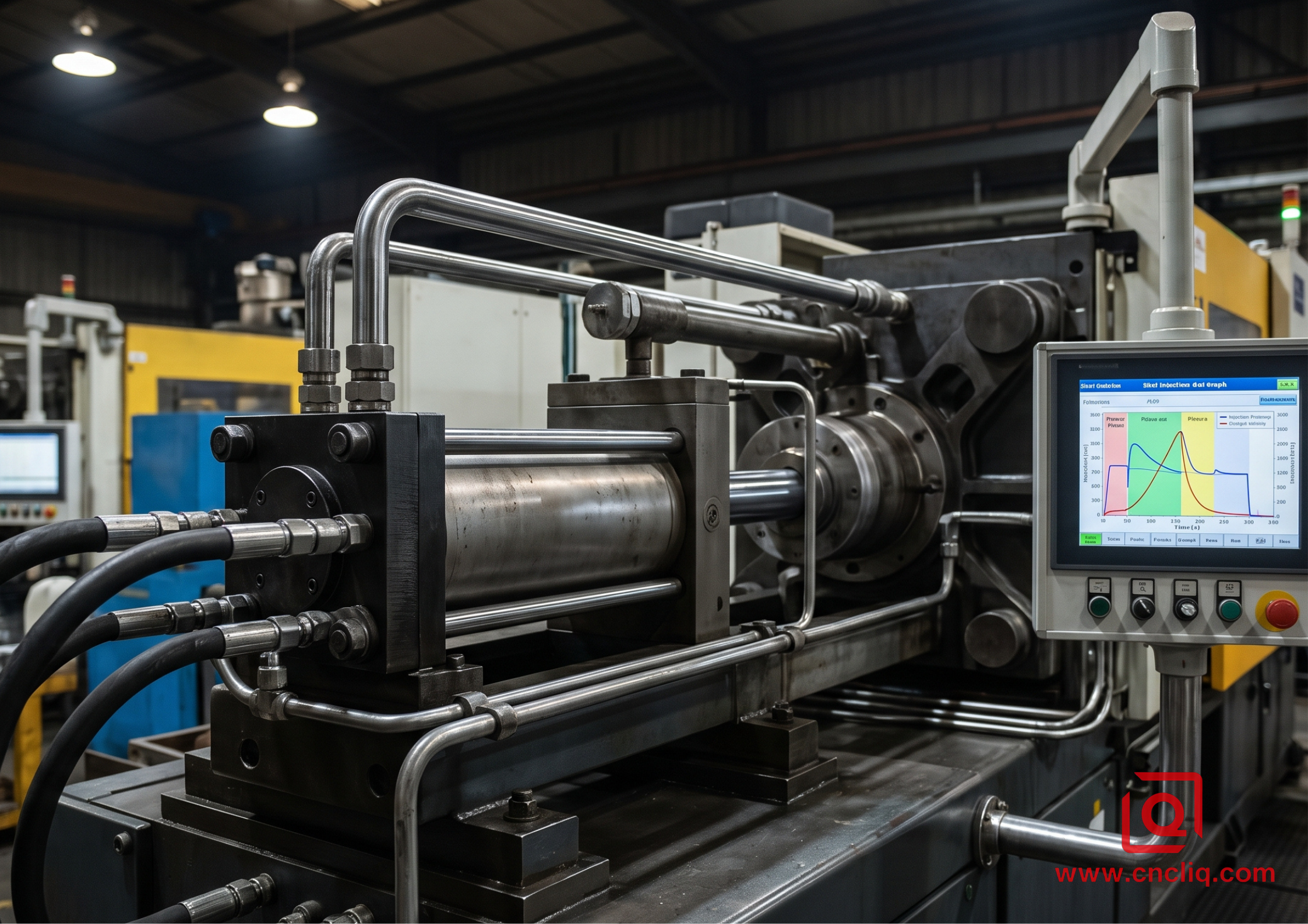
When you tour a potential supplier or audit their equipment roster, do not settle for a basic count of how many cold-chamber machines sit on the shop floor. You need to examine how their press tonnage distribution aligns with your part geometry and whether their injection ends feature real-time closed-loop shot control.
Press mismatch creates chronic quality problems. If a shop forces an intricate, thick-walled pump housing onto a lightweight 350-ton machine, the clamping unit lacks the physical muscle to resist separation forces during the final intensification stage. The result is excessive parting line flash, dimensional growth along the pull direction, and compromised casting density. Conversely, running a lightweight 50-gram sensor bracket on a massive 1000-ton press drives your unit cost unnecessarily high while making delicate shot velocity tuning difficult. In typical high-pressure operations, machines from 280T to 400T handle thin-wall brackets and sensor housings at shot weights between 0.3 kg and 1.8 kg; 500T to 800T presses run motor end covers and pump bodies weighing 1.5 kg to 5.5 kg; and heavy 1000T to 1600T presses tackle large transmission covers and structural battery frames up to 16 kg.
Clamping Force Calculation:
Required Tonnage = [Total Projected Area (cm²) × Specific Metal Pressure (kg/cm²)] / 1000 × Safety Factor (1.2 to 1.3)
Look closely at how the casting cell controls the plunger stroke. In high-pressure aluminum casting, the plunger rod must smoothly transition through three distinct phases:
-
Slow Shot Phase (0.15 to 0.4 m/s): The plunger advances steadily to gather the molten aluminum ahead of the wave without folding air into the runner system.
-
Fast Shot Phase (2.5 to 5.5 m/s): Once the melt reaches the in-gate, the machine accelerates instantly to fill the thin cavity sections within 20 to 50 milliseconds before the alloy begins to freeze.
-
Intensification Phase (700 to 1000 kg/cm²): Immediately upon cavity fill, hydraulic pressure spikes rapidly within 15 to 30 milliseconds to squeeze the cooling metal and pack out solidification shrinkage.
When a supplier runs legacy open-loop equipment, oil warms up across a full shift and causes the hydraulic valves to drift, throwing velocity transition timing off by dozens of milliseconds. That variability leads directly to random cold shuts, surface flow marks, and subsurface gas pockets. Always ask to see sample real-time shot graphs archived directly from their machine controllers.
2. Front-End DFM: Thermal Management and Tooling Architecture
Tooling represents your single largest upfront capital commitment. A capable OEM earns their keep long before toolmakers begin rough-milling premium H13 or Dievar tool steel.
When you evaluate a supplier's Design for Manufacturability (DFM) submission, look for detailed thermal gradient maps and fluid flow simulations rather than static CAD screenshots with generic text. Pay close attention to how the tool designers configure internal conformal cooling lines, spot cooling bubblers, and moving core slides. If a moving slide runs blistering hot above 250°C while adjacent cavity walls hover near 160°C, the resulting uneven cooling rates will warp your primary datum surfaces, making downstream CNC machining impossible.
| Critical Feature / Parameter | Standard As-Cast Limit | Precision OEM Target | Secondary CNC Capability | Primary Engineering Purpose |
| External Wall Draft | 1.0° – 1.5° | 1.5° – 2.0° | N/A (Net Shape) | Prevents drag marks & die soldering |
| Internal Rib Draft | 1.5° – 2.0° | 2.0° – 3.0° | N/A (Net Shape) | Reduces core pin friction during ejection |
| Wall Thickness Transition | 2:1 Max Step | 3:1 Tapered Blend | Coring + CNC Face Mill | Eliminates localized shrink porosity |
| Linear Dimension Accuracy | ±0.20 mm / 25 mm | ±0.10 mm / 25 mm | ±0.015 mm | Controls assembly interface fit |
| Bore True Position | 0.25 mm (Cored) | 0.15 mm (Targeted) | 0.025 mm (CNC Bore) | Guarantees bearing alignment |
During initial drawing reviews, an experienced OEM engineering team should challenge your design on several vital geometric features:
-
Draft Angles: Look for suppliers who actively guide your draft strategy. Outside exterior walls generally require 1.0° to 1.5° of draft, while deep internal pockets and vertical ribs need 1.5° to 2.5° to prevent severe galling, drag marks, and high ejection resistance.
-
Wall Thickness Transitions: Abrupt jumps between heavy mounting bosses and thin structural walls create severe stress concentrations and deep shrinkage cavities. A seasoned casting engineer will suggest gradual tapers using a 3:1 transition ratio, coring out heavy cross-sections to preserve nominal wall consistency.
-
Ejector Pin Layout: Pins need to bear straight down on heavy internal ribs, thick outer walls, or solid bosses. Dropping knockout pins onto cosmetic faces or weak, thin sections leads to warped parts, ugly witness marks, and localized cracking.
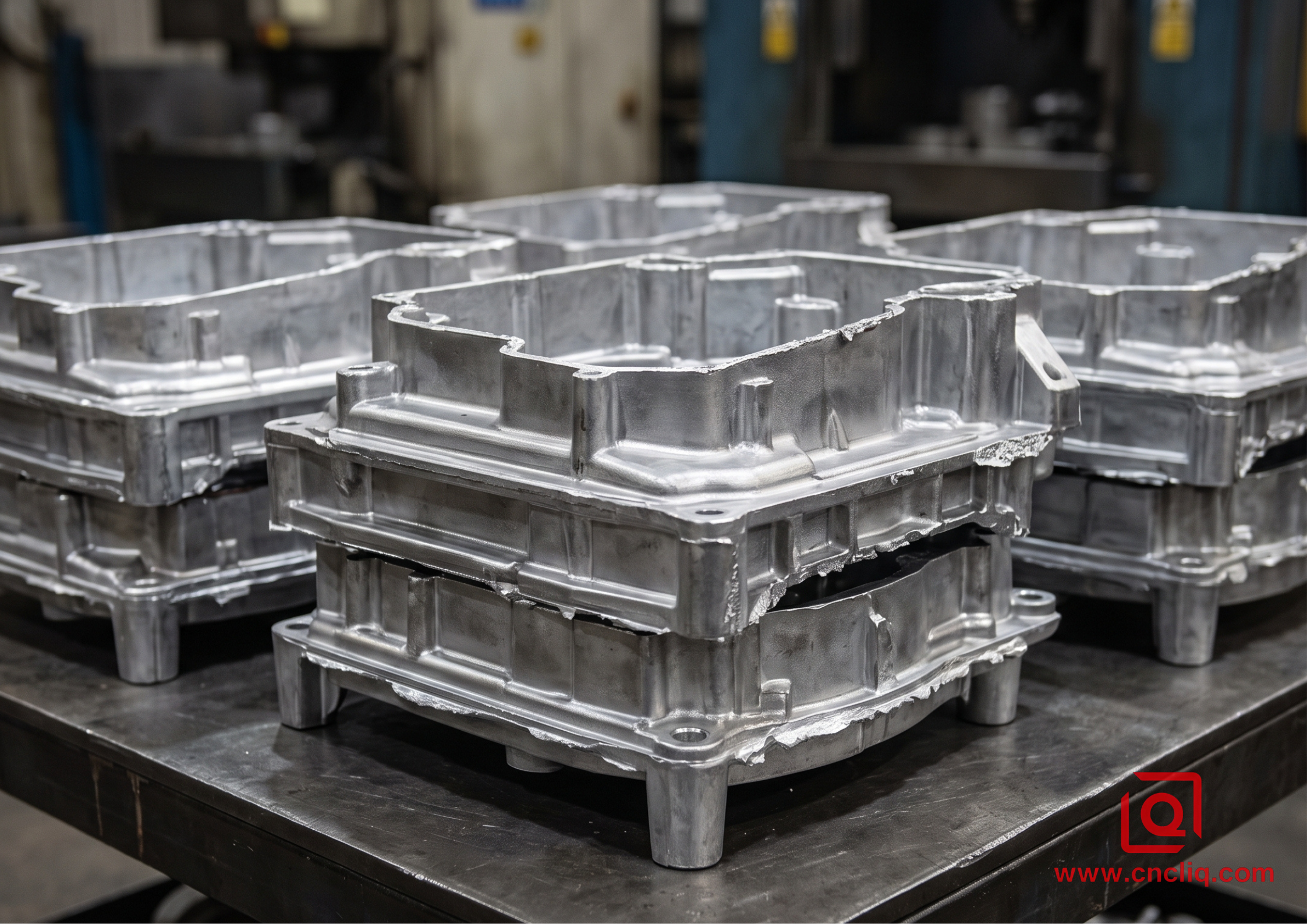
3. Raw Melt Hygiene, Degassing Protocols, and Alloy Control
A signed material test certificate is easy to provide, but genuine mechanical reliability is won or lost at the melting and holding furnaces.
In custom OEM manufacturing, standard alloys like A380, ADC12, and A360 represent the vast majority of production volume. A380 provides a balanced baseline of fluidity and mechanical strength with 7.5% to 9.5% Silicon and 3.0% to 4.0% Copper. ADC12 pushes Silicon up to 9.6% to 12.0%, yielding superior molten fluidity for razor-thin cooling fins and dense enclosures. Meanwhile, A360 limits Copper below 0.6% while keeping Silicon at 9.0% to 10.0%, providing substantially higher ductility and corrosion defense in harsh environments.
However, chemical drift can silently destroy your product's performance if the foundry does not strictly manage its scrap return ratios and furnace charging procedures. When scrap runners and flash are remelted carelessly without tight batch controls, iron (Fe) content can creep above 1.2%. While elevated iron prevents the molten aluminum from sticking to the tool steel faces, it forms brittle, needle-like intermetallic phases that destroy material ductility, dropping elongation below 1.5% and causing carbide cutting tools to chip during finish milling.
Ask the engineering team to walk you through their standard melt preparation routine:
-
Spectrometric Verification: Confirming chemical composition via optical emission spectrometry (OES) for each newly melted furnace batch before metal is transferred to machine holding wells.
-
Rotary Degassing: Purging hydrogen gas and suspended non-metallic oxide inclusions by injecting high-purity nitrogen or argon gas through a rotating graphite impeller.
-
Density Index Testing: Performing vacuum reduced-pressure tests to ensure the density index remains consistently below 1.0% prior to casting critical pressure-tight components.
4. Secondary CNC Machining, Dedicated Fixturing, and Datums
Die casting produces complex near-net shapes quickly, but almost every functional OEM component requires secondary CNC milling, boring, reaming, or tapping to meet demanding assembly tolerances.
This is the exact stage where many low-cost suppliers stumble. They take a raw casting with a 0.3 mm parting line mismatch, clamp it across unmachined draft faces, and then wonder why the final bearing bore position wanders outside the 0.05 mm geometric dimensioning and tolerancing (GD&T) tolerance block.
A professional manufacturing partner develops dedicated pneumatic or hydraulic machining fixtures that register exclusively on designated tooling target pads. These target datums must be formed entirely within one half of the die cavity to avoid parting line variation.
Standard Dimensional Expectations:
* As-Cast Linear Tolerance (NADCA Standard): ±0.20 mm for the initial 25 mm, adding ±0.03 mm per each additional 25 mm
* CNC Finish Milling: True position within 0.025 mm, bore circularity held inside 0.012 mm
* Mating Face Flatness: As-cast baseline of 0.35 mm per 100 mm; post-machined fly-cut surface held to 0.03 mm per 100 mm with a surface finish of Ra 1.6 µm
5. Quality Assurance: Metrology and Leak Testing Under Real Loads
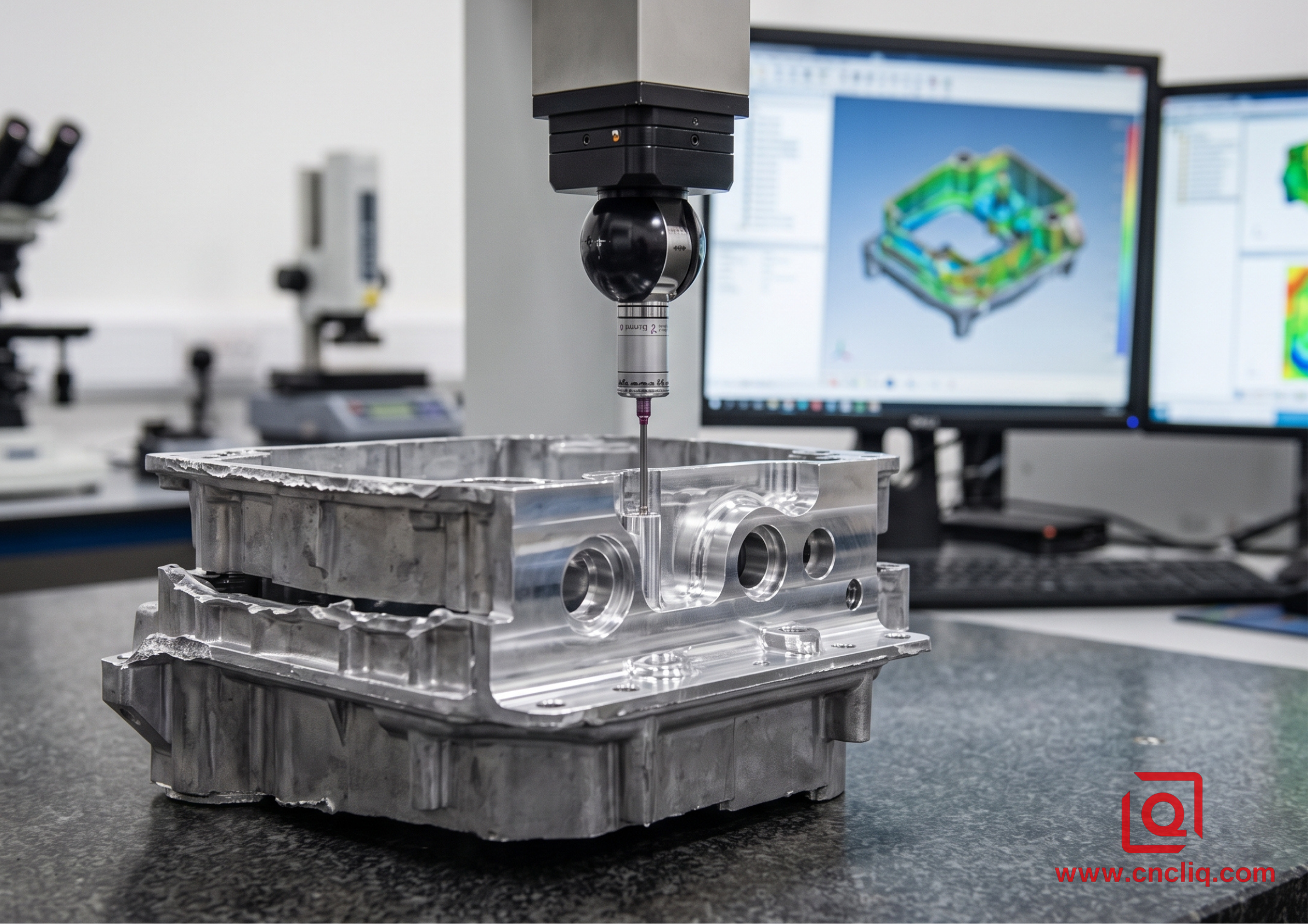
Step inside the QA lab and watch them run real parts before signing off on any initial sample inspection reports (ISIR).
-
X-Ray Flaw Checks: Non-negotiable for load-bearing and fluid-tight parts. While tiny pinholes along low-stress ribs can pass ASTM E505 Level 2 limits, critical O-ring grooves and tapped blind holes cannot show any pore clusters over 0.4 mm.
-
Coordinate Measuring Machines (CMM): Look for automated bridge CMMs equipped with continuous scanning probes, programmed to verify complex 3D profiles and GD&T feature control frames directly from CNC machining centers.
-
Pressure Decay and Helium Leak Testing: Vital for powertrain housings, pump covers, and IP67/IP68 rated outdoor electrical enclosures. Testing should involve differential air pressure decay systems operating at 2.5 bar, holding allowable leak rates strictly under 0.5 sccm (standard cubic centimeters per minute).
Case Analysis: Resolving High-Pressure Porosity in an Industrial Pump Body
To understand how shop-floor problem solving works in practice, consider a real-world case involving a European industrial automation client sourcing an aluminum hydraulic pump housing.
-
Component Description: Heavy-duty fluid power end-plate
-
Specified Alloy: ADC12 aluminum
-
Customer Pain Point: The client experienced localized oil weeping through a 14 mm thick central mounting boss during end-of-line pressure testing at 18 bar hydraulic pressure.
During the initial trial batch, the machine ran with a low 42% shot sleeve fill ratio, a gate velocity of 38 m/s, an intensification pressure of 680 kg/cm², and standard atmospheric venting. This configuration generated a severe 14.8% scrap rate under 20 bar pressure testing. In contrast, the optimized production setup increased the fill ratio to 68% using a smaller sleeve, boosted gate velocity to 46 m/s, raised intensification pressure to 920 kg/cm², and applied an 85 mbar sub-atmospheric vacuum, bringing leak scrap down to an absolute 0.0%.
The Shop-Floor Investigation and Remedy:
The technical team sectioned several leaking samples across the heavy boss using a precision band saw and subjected the cross-sections to macro-etching. The analysis revealed two interconnected root causes:
-
Wave Entrapment in the Sleeve: The initial 70 mm shot sleeve had a low fill ratio of only 42%. During the slow shot movement, the metal formed a rolling wave that trapped air inside the sleeve, pushing air bubbles straight through the runner and into the part.
-
Premature Gate Freezing: The thin in-gate froze solid before the machine's final intensification stage could feed liquid metal into the 14 mm thick boss, leaving localized shrinkage voids.
The Corrective Action Plan:
-
Downsized Shot Sleeve: The sleeve diameter was reduced from 70 mm to 55 mm, raising the fill volume to 68% and eliminating plunger wave turbulence.
-
Hydraulic Squeeze Pin: A dedicated high-pressure squeeze pin was installed in the moving die core directly aligned with the heavy boss, programmed to trigger 1.8 seconds after injection to physically compress the internal shrinkage pocket while the core was still semi-solid.
-
Targeted Conformal Water Lines: Fast-flowing chill circuits were drilled close around that thick boss to speed up local cooling and balance solidification.
-
Vacuum Evacuation: A sub-atmospheric vacuum unit pulled cavity pressure down to 85 mbar to strip out trapped air during the fast shot.
With these fixes in place, a 5,000-piece run delivered zero leak rejects and blew past the 25 bar proof pressure burst test.
Essential Audit Checklist for Global B2B Buyers
When you conduct an on-site audit or virtual technical review of an overseas die casting supplier, use this practical checklist to separate capable contract manufacturers from basic job shops:
[ ] In-house tooling engineering equipped with Flow-3D or MAGMA mold-flow simulation software
[ ] Verified tool steel sourcing (Certified premium H13, Dievar, or 1.2344 heat-treated to 46–48 HRC)
[ ] Real-time shot velocity and pressure curve monitoring on all casting machines
[ ] Rotary degasser stations with automated nitrogen fluxing and density index verification
[ ] CNC machining fixtures locating on single-die-half datum pads rather than parting lines
[ ] In-house metrology lab with calibrated CMM, OES spectrometer, and digital leak decay testers
[ ] Complete post-processing and finishing control (Shot blasting, passivation, powder coating, anodizing)
[ ] Clear traceability linking casting heat lots, machine parameters, and CNC inspection records
FAQs
Q1: What are the most common signs that an aluminum die casting mold is poorly designed?
On the shop floor, flawed tooling shows up immediately. You will see heavy drag marks along vertical walls, ragged parting-line flash, and castings hanging up in the fixed half at ejection. Inadequate waterlines cause parts to warp as they cool, while undersized gates and choked vents leave stubborn trapped air and distinct cold shuts across the skin.
Q2: How does a good OEM prevent porosity in thick-walled sections of a casting?
Reliable foundries tackle shrinkage porosity early during DFM by adding coring pins to maintain uniform wall thickness. On the production floor, toolmakers integrate dedicated spot-cooling lines around heavy sections to balance solidification rates, use local hydraulic squeeze pins to mechanically compress the mushy metal, and apply vacuum systems to evacuate trapped air from the cavity.
Q3: Can aluminum die casting achieve watertight or airtight sealing without secondary sealing treatments?
Yes, provided the OEM controls the shot parameters and tool thermal balance properly. Net-shape die castings routinely achieve IP67 or high-pressure leak-tight performance as long as the sealing surface runs free of parting line steps, flow turbulence is minimized near the gasket groove, and fine-grain melt degassing prevents interconnecting micro-porosity channels.
Q4: What causes machining tools to wear out unusually fast when milling die cast aluminum?
Rapid tool wear almost always traces back to raw material contamination at the melting furnace. Overloading the melt with dirty foundry scrap precipitates needle-like iron-silicon intermetallics right through the matrix. Pair that with leftover slag oxides acting as miniature grinding grits, and your carbide inserts will chip out fast during high-speed CNC milling.
Q5: Why is it risky to use raw cast surfaces as primary locating datums for secondary CNC machining?
Raw cast surfaces inherit subtle variations from tool wear, uneven thermal expansion, and parting line shifts between the two mold halves. Clamping directly on an untreated draft face introduces angular misalignment, causing finished hole positions and milled faces to wander outside drawing tolerances even when the CNC machine itself runs perfectly.
Summary
Buying custom aluminum die castings is not a standard purchase order; it is hands-on technical teamwork. A good supplier does far more than shoot parts off your 3D models—they challenge thin walls and sharp radii, flag hot spots, tweak melt chemistry, and lock down stable cycles that keep bad parts out of the field.
Weighing potential vendors means looking at real engineering chops instead of sales pitches. Pick teams that talk clear manufacturing realities, master high-pressure liquid metal dynamics, and own mold life, part tolerances, and structural integrity. Lock those fundamentals down, and your offshore supply line reliably turns out spec-compliant parts on schedule and within budget.
Contact Information
Disclaimer
All technical articles, material specifications, machining recommendations, and surface treatment details published on this blog are for informational and reference purposes only. Please note that general blog insights do not replace signed technical agreements. Because custom parts vary by material heat numbers, machine calibrations, and specific tolerances, binding quality specs are governed solely by your approved CAD drawings, signed contracts, and formal quality plans.
All customer case studies featured on this blog have been thoroughly anonymized and sanitized. The performance metrics, manufacturing workflows, and imagery displayed serve solely to demonstrate our custom machining capabilities and do not represent a single universal standard for all orders.
Liqin Manufacturing Team
Built on 18 years of precision engineering experience, Ningbo Liqin Industry manufactures high-tolerance metal components for demanding global markets. We operate out of a 6,500 m² production hub equipped with over 150 machines, running 4-axis and 5-axis CNC machining, mill-turn machining, cold extrusion, and pressure die casting under one roof. This setup allows us to manage projects seamlessly, taking parts from initial CAD concepts directly to finalized shipments.
We handle quality control with zero compromise. We treat tight tolerances with the engineering discipline they require. Backed by ISO 9001, ISO 13485, and IATF 16949 certifications, our QA engineers run strict IPQC, FQC, and OQC checks on every single production batch. From CMM dimensional mapping and optical profiling to hardness and salt-spray testing, we validate your critical specs upfront—so you receive drop-in ready components with zero assembly headaches or costly line stoppages. On top of manufacturing, you can rely on us for two-hour response times on new RFQs, direct support for prototype sampling, and smooth export shipping across Europe, North America, Asia, and Oceania.
Welcome your inquiries and samples. Visit our website or contact us directly for a competitive quote!
