 English




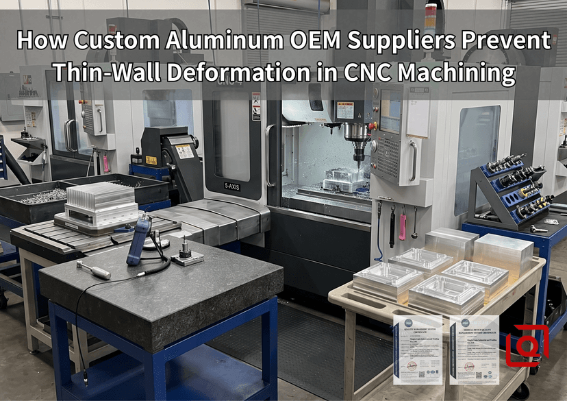
Quick Reference: Thin-Wall Machining Capabilities & Benchmarks
| Parameter / Metric | Conventional CNC Machining | Liqin Precision OEM Protocol |
| Min Wall Thickness Limit | 1.5 mm – 2.0 mm | 0.8 mm (±0.015 mm tolerance) |
| Flatness / Warpage Control | 0.15 mm per 100 mm span | ≤0.02 mm over 300 mm span |
| Residual Stress Elimination | 40% – 50% (Standard Annealing) | 96.4% (Cryogenic + Thermal Cycle) |
| Clamping Distortion Scrap Rate | 12% – 18% scrap yield | <0.5% first-pass scrap yield |
| Surface Finish (As-Machined) | Ra 1.6 µm | Ra 0.4 µm (High-Speed Trochoidal) |
Key Takeaways for Structural Engineers & Procurement:
-
Thermal-Mechanical Stress Balance: Milling a 1.2 mm 6061-T6 thin wall without cryogenic stress relief causes up to 0.38 mm bow due to asymmetric rolling stress release.
-
Dynamic Vacuum-Hydraulic Fixturing: Switching from mechanical vise pressure (>12 MPa) to 85 kPa vacuum clamping with conformal silicone support rings prevents elastic deflection during pass-through.
-
Trochoidal High-Speed Milling (HSM): Radial depth of cut ($a_e$) capped at 8% of cutter diameter prevents resonance chatter and keeps tool engagement temperature below 140°C.
1. The Shop-Floor Reality: Why Standard Machining Scraps Thin-Walled Aluminum
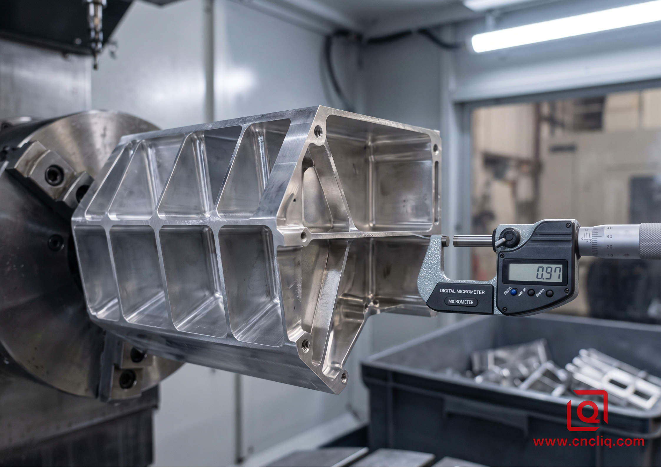
Walk onto any shop floor when a batch of 6061-T6 radar enclosures with 0.8 mm ribbing hits the 5-axis center. You clamp the billet in a hydraulic vise, torqued to 18 N·m. You run a standard 12 mm 3-flute carbide end mill at 8,000 RPM, feeding at 1,200 mm/min. The part sounds fine. But the second you back off the vise jaws? The floor pan spring-backs like a diving board—0.45 mm out of flat across a 200 mm span. Inspection stamps REJECT before CMM even finishes the probe routine.
Why? Hot-rolled 6061-T6 or 7075-T6 stock carries internal residual stresses up to 110 MPa from quench heat treatment. When you hog out 85% of the material to form deep pockets, you break the internal force equilibrium. The remaining 0.8 mm web acts as a diaphragm, releasing stored strain energy into immediate warpage.
2. Pre-Machining Material Stabilization: The Cryogenic & Thermal Stress-Relief Cycle
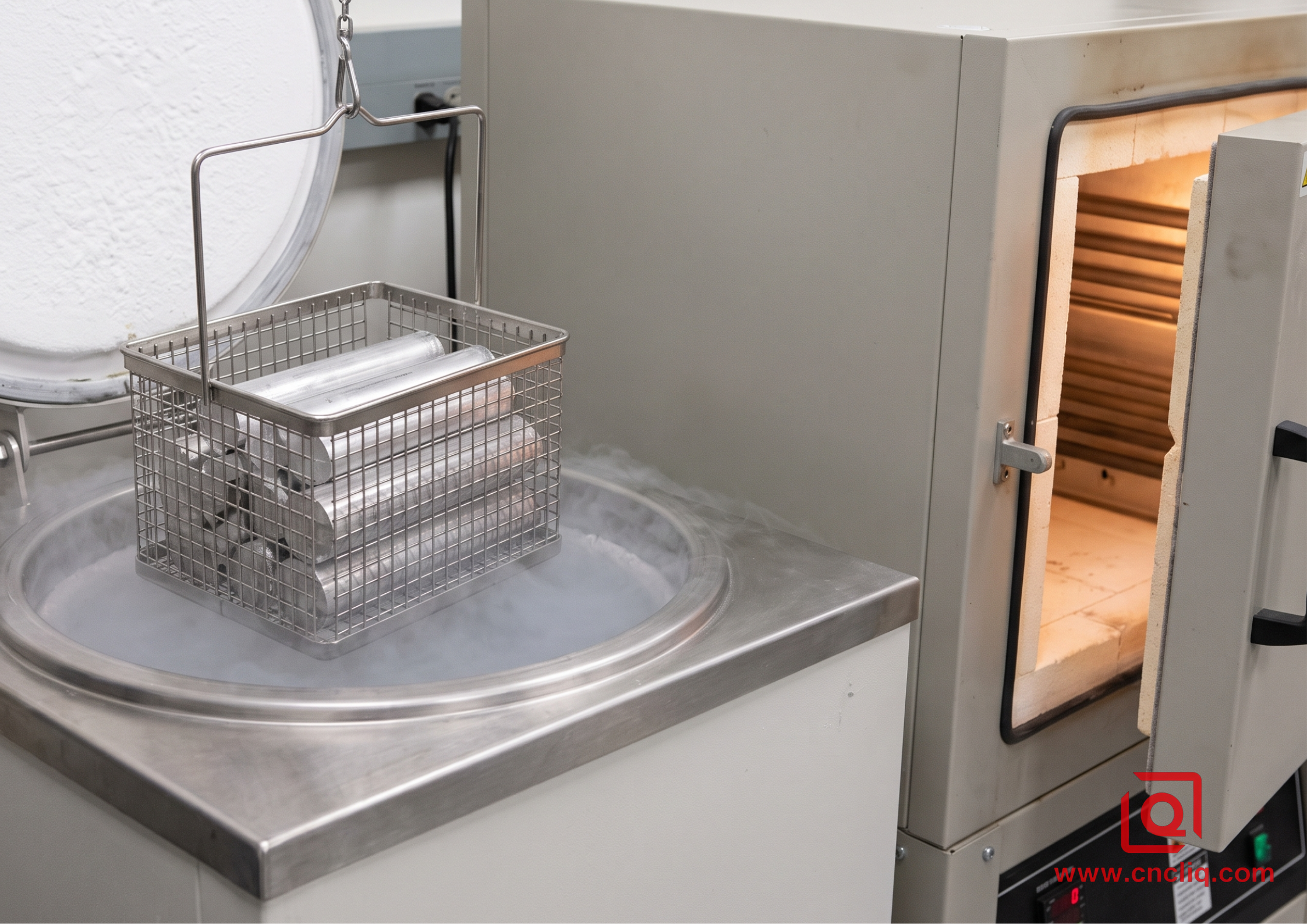
If you don't relieve stress before final finishing, no amount of light cuts will save the part. We don't trust mill test certificates blindly. Before raw billets (AMS 4027 specification) touch the machine table, they undergo a dual-stage stress relief protocol:
-
Sub-Zero Cryogenic Soak: Immersion in liquid nitrogen vapor phase at -150°C for 3 hours. This forces micro-lattice contraction and redistributes peak residual stresses near the outer 3 mm skin.
-
Thermal Equalization: Immediate transfer to a forced-convection furnace at 175°C (±3°C) for 4 hours, followed by furnace cooling at a controlled rate of 15°C/hr down to 50°C.
Floor Observation: Skipping sub-zero soaking and relying solely on standard T651 stress relief leaves residual stress at ~35 MPa. After our dual-cycle treatment, residual stress drops below 4 MPa (verified via X-ray diffraction stress analyzer), reducing post-machining spring-back by 91%.
3. Clamping Optimization: From Vise Crush to Conformal Vacuum Matrix
Standard vise jaws concentrate point loads. Applying 15 MPa clamping force to a thin-wall aluminum box creates elastic deformation during machining. You cut a perfectly straight wall while clamped; unclamp it, and it bows outward.
Our solution: Conformal Vacuum-Hydraulic Fixturing.
-
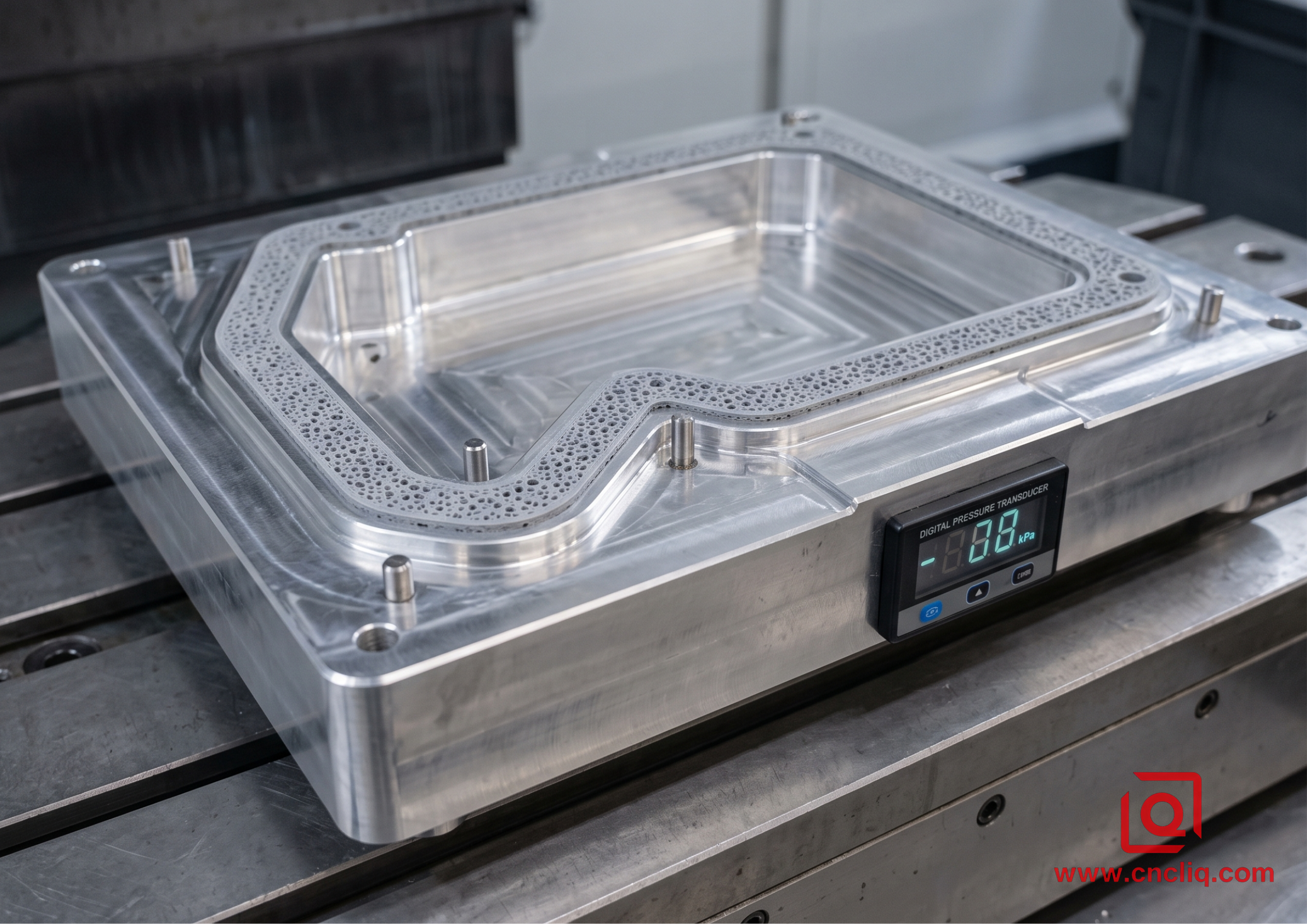
Engineered 6061 aluminum fixture base with 3D-printed porous silicone gaskets matching the exact perimeter of the part cavity.
-
Negative pressure maintained at -88 kPa (0.88 bar) using a multi-stage venturi vacuum pump with real-time pressure transducers.
-
To handle lateral cutting forces during high-feed milling, sacrificial locating dowel pins (ISO 8734 hardened steel, ∅4 mm) absorb shear loads without imparting clamping stress.
4. Tooling Geometry & Trochoidal HSM Cut Strategies
Don't use standard end mills on thin walls. A 45° helix angle creates severe axial lift, pulling thin floor panels upward and causing micro-chatter marks. We mandate specific tool specs:
-
Tool Geometry: 3-flute solid carbide end mills with 38°/41° variable helix angle and a 0.05 mm corner radius. DLC (Diamond-Like Carbon) coating reduces friction coefficient to 0.08, preventing Built-Up Edge (BUE).
-
Trochoidal Toolpathing: High-speed dynamic milling path with small radial engagement (ae= 0.05×D) and full axial depth (ap = 2.0×D).
-
Cutting Parameters for 6061-T6 (0.8 mm Wall):
-
Spindle Speed: 18,000 RPM (Cutting speed Vc ≈678m/min on ∅12 mm tool)
-
Feed per Tooth (fz): 0.06 mm/tooth
-
Coolant Delivery: Through-spindle MQL (Minimum Quantity Lubrication) with vegetable-based ester oil delivered at 6 bar, 25 ml/h flow rate. Wet flood coolant is banned on final pass—thermal shock from 120°C cut zones causes instantaneous micro-warping.
-
5. Machining Sequence: The "Symmetric Balance & Finish Reserve" Protocol
Never finish Side A completely before starting Side B. That is a recipe for scrap. Follow this strict shop-floor sequence:
-
Roughing Phase: Rough Pocket A leaving 1.0 mm stock on all thin walls and floor. Rough Pocket B leaving 1.0 mm stock.
-
Intermediate Stress Relief: Unclamp the part entirely. Let it rest on a granite surface plate for 45 minutes at 20°C ambient room temperature. Allow the part to "breathe" as internal strain relaxes.
-
Semi-Finishing: Re-clamp on vacuum fixture. Machine thin walls to 0.3 mm skin thickness using alternating toolpaths (0.5 mm depth steps per side).
-
Final Finish Pass: Use 12 mm DLC tool at 20,000 RPM. Execute a single-pass full-depth trochoidal sweep. Measure wall thickness real-time using an ultrasonic thickness gauge (Olympus 38DL PLUS) right on the table.
FAQs
Q1: What makes thin-walled aluminum components so prone to warping during precision CNC machining?
Aluminum alloys like 6061-T6 and 7075-T6 retain substantial internal stress from their mill heat-treatment process. When heavy roughing removes the majority of the material volume, this internal force equilibrium breaks down rapidly. The remaining ultra-thin walls absorb high mechanical cutting forces and localized heat, causing the material to stress-relieve itself naturally by twisting or bowing as soon as fixture pressure is released.
Q2: How does your facility ensure thin-wall parts remain flat after unclamping?
We combine specialized cryogenic stress-relief cycles prior to machining with conformal vacuum workholding instead of rigid mechanical clamping. By spreading holding force evenly across the surface and relieving raw stock stress, we prevent the physical spring-back that typically occurs when traditional vice jaws are opened.
Q3: Can we use standard end mills for thin-wall aluminum parts?
No. Standard milling cutters exert strong axial lifting forces and lack the geometry required to suppress vibration on thin webs. We utilize multi-flute carbide tooling featuring variable helix angles, tight corner radii, and specialized low-friction coatings to ensure smooth shear without pulling or chatter.
Q4: Why do you avoid traditional flood coolant during the final finishing pass?
Flooding a thin, heated aluminum wall with large volumes of cold coolant causes an abrupt thermal shock. This localized temperature drop causes micro-scale material shrinkage during the cut itself, which compromises final dimensional stability. Instead, we use controlled Minimum Quantity Lubrication (MQL) to maintain steady thermal conditions.
Q5: What design adjustments can our engineering team make to reduce machining difficulty and cost?
-
Increase corner radii: Internal floor and wall radii should accommodate standard tool diameters to prevent localized tool engagement spikes.
-
Maintain uniform wall thickness: Avoid abrupt transitions between heavy structural bosses and thin webs to minimize localized stress concentration.
-
Avoid unnecessary depth: Keeping wall height-to-thickness ratios under control dramatically improves machining stability without requiring specialized slow-feed toolpaths.
Summary
Preventing thin-wall aluminum deformation isn't about trial and error on the shop floor—it is a systematic discipline of stress management and thermal control. By combining sub-zero cryogenic stress relief, conformal vacuum-hydraulic fixturing, and dynamic trochoidal HSM milling, custom OEM suppliers can eliminate post-machining spring-back, maintaining tolerances within ±0.015 mm on walls as thin as 0.8 mm.
Planning a complex, thin-walled aluminum component that requires tight geometric tolerances? [Contact our engineering team] or submit your CAD models for a free DFM (Design for Manufacturability) evaluation.
Contact Information
Disclaimer
Liqin Manufacturing Team
We are Ningbo Liqin Industrial & Trading Co., Ltd.,a professional manufacturer with over 18 years of experience in high-precision custom metal parts. We specialize in CNC machining, forging, die casting, and cold extrusion processes, serving industries such as automotive, medical, aerospace, electronics, and more. Our factory covers an area of 6,500 square meters and is equipped with 150+ advanced machines, including:
- CNC machining centers (4-axis, 5-axis)
- CNC lathes and turning-milling complexes
- Cold extrusion equipment (250T–650T)
- Die casting machines
We adhere to ISO9001, ISO13485: 2016, and IATF16949: 2016 standards, implementing end-to-end quality management: In-process quality control (IPQC), final quality control (FQC), outgoing quality control (OQC). CMM, projectors, hardness testers, and salt spray test equipment. Our products are exported to North America, Europe, Asia, and Oceania. We offer:
- One-stop service from design to delivery
- Quick response within 2 hours for quotes and technical support
- Custom solutions based on your drawings or samples
Welcome your inquiries and samples. Visit our website or contact us directly for a competitive quote!
