 English




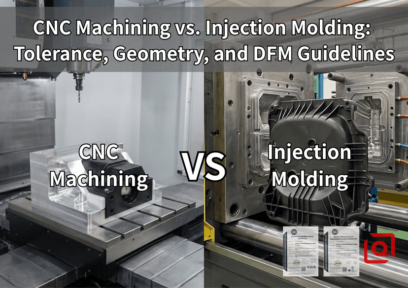
On a computer monitor, every 3D model looks flawless. Surfaces mate with zero play. Corners stay mathematically crisp. Wall sections shift from razor-thin to massive blocks without a hiccup.
Drop that STEP file straight onto the shop floor. Green-button a 3-axis VMC, and your 4-flute carbide cutter is chewing through solid stock at 10000 RPM. Throw that identical model at tooling, and you're shooting molten resin at 1000 bar into cut steel. The plastic solidifies, shrinks tight to the core pins, and ejector pins pop it free.
Both routes yield precision parts, yet their physics clash completely. Treat an injection molded part like a billet-milled run, and you'll fight wicked warp, ugly sinks, and expensive tool mods that wreck your margin. Here is the unvarnished look at the real-world geometry, true tolerance stack-ups, and shop-floor DFM trade-offs we sweat over daily.
+-------------------------------------------------------------------------+
| CNC Machining: Tool Path + Spindle Rigidity -> Subtractive Shaping      |
| Injection Molding: Melt Flow + Mold Pack + Cooling Shrink -> Replicative |
+-------------------------------------------------------------------------+
1. The Tolerance Divide: ISO 2768 vs. DIN 16742
Machinists and mold builders do not speak the same language when reading prints.
On a machining center, your limits come down to machine frame stiffness, spindle thermal expansion, cutter deflection, and fixture repeatability. For billet aluminum (like 6061-T6 or 7075) and rigid polymers (like POM-C or PEEK), we build around ISO 2768-m (medium) or ISO 2768-f (fine).
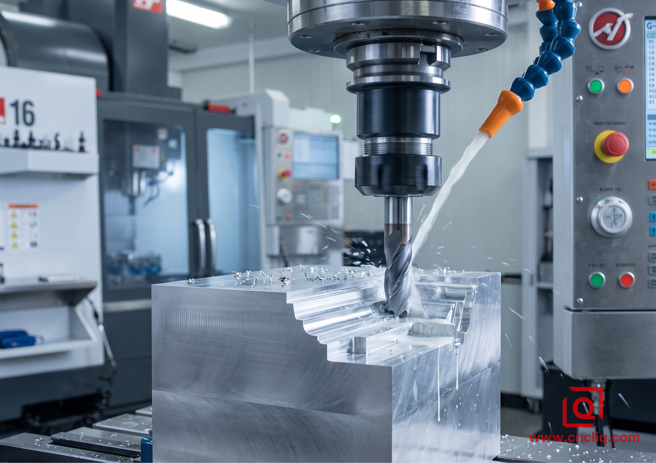
A standard CNC milling pass routinely holds +/- 0.05 mm across 100 mm of travel. Set up a dedicated bore finishing cycle with a custom boring bar or a carbide reamer, and you can lock bearing journals into +/- 0.008 mm with 0.005 mm runout.
CNC Precision Stack:
Machine Rigidity + Workholding Repeatability -> Holds +/- 0.010 mm to +/- 0.050 mm
Molding is a different animal.
The moment mold clamps unlock, the part is still shrinking. Volumetric shrinkage, thermal gradients across cooling lines, molecular orientation, and pack pressure drop make tight linear spans tricky.
Plastic parts run under DIN 16742 (Tolerance Groups TG1 to TG9) or ISO 20457. An unfilled semi-crystalline material like Polyoxymethylene (POM) will shrink anywhere from 1.8% to 2.2%. Amorphous polymers like ABS shrink less, typically 0.4% to 0.7%.
Molding Tolerance Stack:
Tool Steel Cavity +/- Mold EDM Accuracy - Resin Shrinkage +/- Warpage -> Realistic: +/- 0.10 mm to +/- 0.30 mm
Demanding +/- 0.05 mm across a 120 mm molded POM bracket without in-cavity pressure sensors, dialed-in hot runners, and cooling fixtures is asking for high scrap rates. On a 3-axis mill? That is an everyday job.
| Parameter / Feature | CNC Machining (Metals & Engineering Plastics) | Plastic Injection Molding (Thermoplastics) |
| Applicable Standard | ISO 2768-m / ISO 2768-f | DIN 16742 (Standard TG4 to TG6) |
| General Linear Tolerance | +/- 0.025 mm to +/- 0.050 mm | +/- 0.100 mm to +/- 0.300 mm |
| Precision Feature Tolerance | +/- 0.005 mm to +/- 0.012 mm (Bored/Reamed) | +/- 0.050 mm (Matched steel core inserts) |
| Surface Finish Target | Ra 0.8 um to Ra 3.2 um (As-machined) | SPI A-2 (High Polish) to SPI D-3 (Matte Blast) |
| Primary Process Roadblock | Tool chatter, part deflection, setup errors | Asymmetric shrink, gate freeze, molded stress |
| True Position (GD&T) | Down to DIA 0.02 mm (Single setup datum) | Typically DIA 0.15 mm to DIA 0.30 mm |
2. Geometry Rules and What the Shop Floor Rejects
I see this constantly: an engineering team hogged out a beautiful POM prototype on a 5-axis machine, tested the mechanics, loved the fit, and immediately uploaded that exact 3D file for production tooling quotes.
The mold shop sends back a redlined model full of DFM change requests. Why? Because geometry that is trivial for a milling cutter will wreck an injection mold.
       CNC MILLING POCKET                   INJECTION MOLDED CAVITY
  +--------------------------+           +--------------------------+
  |                          |           |  |                    |  |
  |  90 deg Sharp Inside     |           |  | 1.5 deg Draft Wall |  |
  |  Corner (NO GO for End   |           |  |                    |  |
  |  Mill -> Needs R Corner) |           |  | Uniform Nominal    |  |
  |                          |           |  | Wall Thickness     |  |
  |  Flat Deep Bottom        |           |  | (Cored-out Base)   |  |
  +--------------------------+           +--+--------------------+--+
Wall Thickness and Reinforcing Ribs
-
CNC Milling: You can leave arbitrary wall steps. Cut a 1.5 mm web directly into a 10.0 mm mounting boss. The cutter does not care. The only headache is thin-wall vibration. If an aluminum fin drops below 0.8 mm, or plastic below 1.5 mm with a high aspect ratio (> 8:1), the cutter squeals, chatters, and pushes the stock out of square.
-
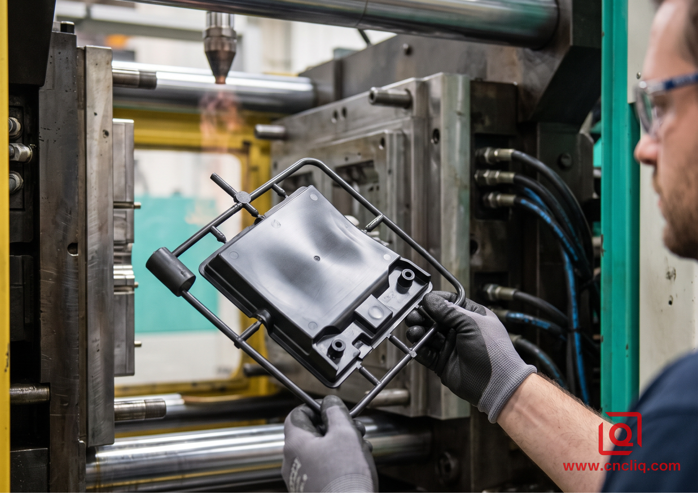
Injection Molding: Keep your nominal wall uniform. Thickness variations ruin cycle times and part quality. If you feed molten resin through a 1.5 mm area into a 4.5 mm thick boss, the thin section freezes off first. The molten core in the heavy section keeps cooling, contracts, and pulls the outer skin inward, leaving visible sink marks or internal voids.
-
Rib Proportioning: Never match rib thickness to the nominal wall. Keep rib bases between 40% and 60% of the adjacent wall thickness (e.g., a 1.2 mm rib running off a 2.5 mm wall). Add at least 0.5 deg of draft per side. That stops the resin from pulling a sink mark onto your visible surface.
Inside Corners: Cutters vs. Sinker EDM
-
CNC Milling: A rotating end mill cannot cut a square vertical inside corner. A 6.0 mm flat end mill leaves a minimum R 3.0 mm fillet. If a mating component has sharp square edges, you either design a dog-bone relief pocket or pay for a secondary wire EDM operation.
-
Injection Molding: We can burn dead-sharp square corners into P20 or H13 tool steel with sinker EDM electrodes. But sharp inside corners on the molded plastic piece become stress risers. Drop the part, and it splits along that root. Always blend your internal junctions with an inside radius of 25% to 50% of the nominal wall (never go below R 0.5 mm).
Draft Angles and Side Undercuts
-
CNC Milling: Zero draft required. End mills cut true 90 deg vertical walls all shift long. The only practical watchpoint is your reach ratio: keep pocket depth within 4x the cutter diameter, or tool deflection will ruin your dimensional plan.
- Injection Molding: Lock down consistent wall thickness across your part. Wall shifts will crush your cycle times and yield. If plastic flows through a 1.5 mm rib before reaching a 4.5 mm boss, the narrow section freezes off early. That isolated thermal mass keeps shrinking inside, sucking the outer surface in to create ugly sink marks or internal voids.
- Rib Design: Never size ribs 1:1 with your nominal wall. As a rule of thumb, target 40% to 60% of the adjacent wall at the rib base—say, a 1.2 mm rib on a 2.5 mm main wall. Always pull at least 0.5 deg of draft per side.
3. Stock Properties: Billet Slab vs. Molten Shot
Take the exact same resin grade. A block of extruded stock behaves differently under tool load than resin shot through a sprue bushing.
Extruded Billet (CNC Subtractive):
* Frozen-in extrusion stresses across raw stock
* Dense, isotropic mechanical behavior
* Requires mid-cycle stress relief (e.g., POM-C at 140 deg C)

Molded Part (Tool Cavity):
* High shear flow orientation (anisotropic strength along flow paths)
* Differential cooling shrinkage depending on gate placement
* Weld lines where split flow fronts converge
Machining Stresses vs. Mold Residual Strains
When hogging a massive pocket out of a 30 mm thick extruded POM-C or PEEK plate, removing skin material disrupts the stress balance left over from raw stock manufacturing. The stock bows. The fix? Rough out the shape, leave 0.5 mm stock on all datums, bake the block in an annealing oven to normalize stresses, then come back for the light finish passes.
In injection molds, residual stress tracks back to uneven pack pressure and poor thermal control. If cooling circuits run hotter on the core side than the cavity side, the part curls the moment ejector pins push it off the tool.
4. Field Case Study: Redesigning a Fluid Flow Housing
Here is a practical example from our shop floor involving an optical sensor flow body for an industrial fluid monitoring project.
Initial Issue:
[Solid CNC POM-C Block: 4.5 mm thick base, 0 deg draft, sharp internal steps, +/- 0.02 mm bore]
                     |
                     v (Attempting direct mold transfer)
[Molding Failure: Deep surface sink marks, 0.4 mm base bow, core pin drag]
1. Prototype Phase (CNC Milling)
-
Material: POM-C (Acetal Copolymer).
-
Initial Geometry: Cut from a solid billet. 4.5 mm thick bottom, zero draft on deep fluid pockets, sharp 90 deg steps, and a critical DIA 12.000 mm (+/- 0.015 mm) optical sensor bore.
-
Result: 20 prototype units machined clean. Bores held true with a finishing reamer. Flow tests passed inspection.
2. The Production Hurdle
The customer greenlit a 15000-unit-per-year production run and wanted a 4-cavity injection mold built straight off the prototype CAD file.
Our DFM review caught immediate red flags:
-
The 4.5 mm thick base would stretch cooling cycle times past 40 seconds and pull deep sink marks right across the sealing lands.
-
The zero-draft pocket walls would drag hard on mold core pulls.
-
Holding +/- 0.015 mm on the raw molded DIA 12 mm bore across four cavities with POM (2.0% shrinkage) would drive scrap rates through the roof.
DFM Correction Path:
1. Core out solid 4.5 mm floor to a uniform 2.2 mm nominal wall.
2. Add 1.5 deg draft to all deep core features.
3. Blend R 0.8 mm fillets into sharp internal intersections.
4. Mold sensor bore undersized at DIA 11.60 mm -> CNC finish ream to DIA 12.000 +/- 0.008 mm.
3. Practical DFM Adjustments & Hybrid Strategy
-
Coring Out Heavy Sections: We shelled the 4.5 mm floor to a consistent 2.2 mm nominal wall, reinforced from behind with 1.1 mm ribs (50% rib-to-wall ratio). Molding cooling time dropped from 42 seconds down to 16 seconds.
-
Adding Draft: Added 1.5 deg draft to all vertical chamber cores and 1.0 deg along fluid channels, preserving the O-ring shutoff line.
-
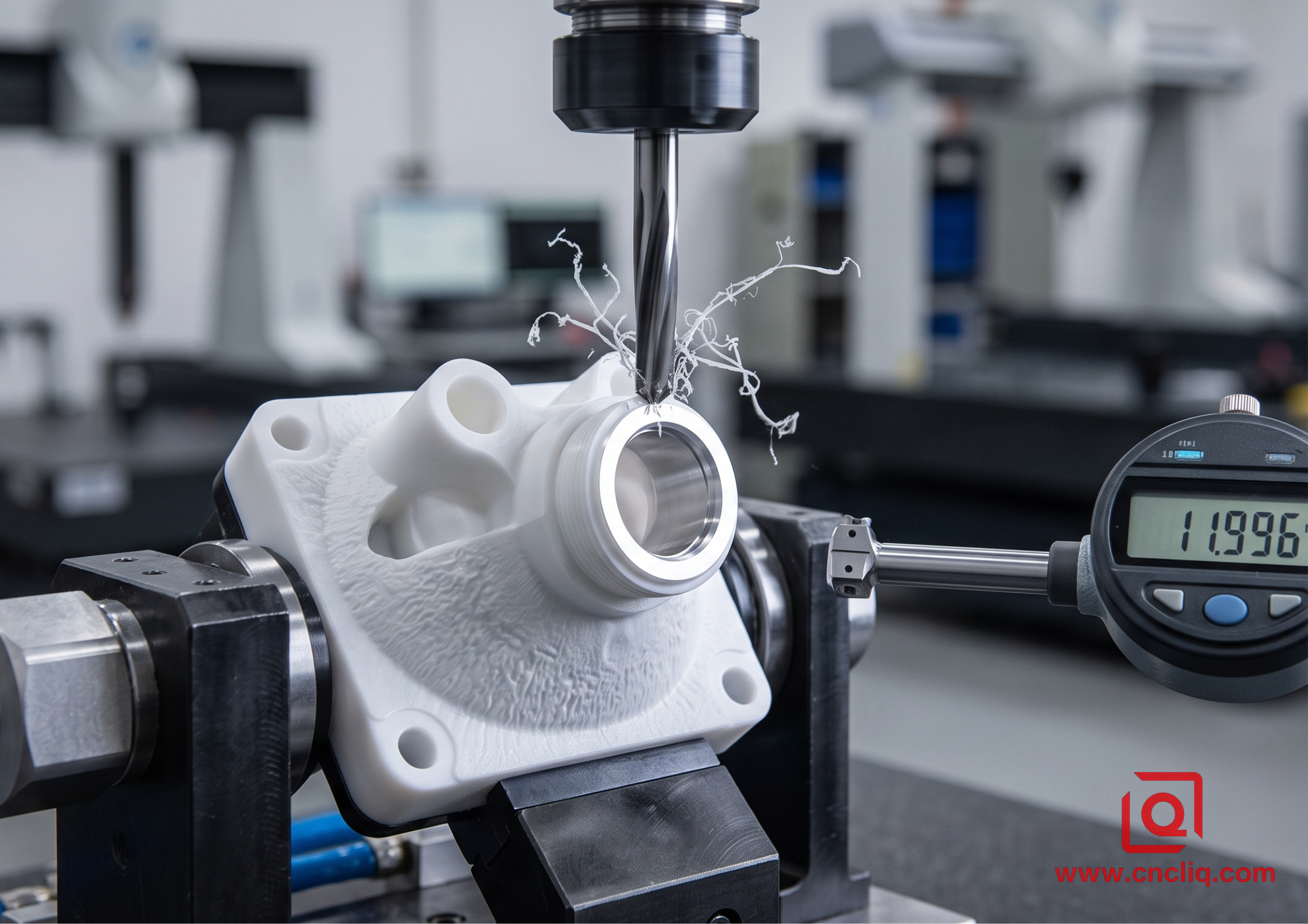
Tolerance Segregation (Hybrid Manufacturing): We stopped trying to hit +/- 0.015 mm directly inside the mold cavity. Instead, we cored the hole to DIA 11.6 mm on a stout mold pin. We then routed the molded shots to a dedicated CNC cell, using an automated pneumatic fixture and a solid carbide reamer to finish the DIA 12.000 mm bore to +/- 0.008 mm.
Final Run Metrics:
Cycle Time: Cut by 61% (42s down to 16s)
First-Pass Yield: 99.2%
Sensor Bore Dimension: Locked into +/- 0.008 mm via secondary CNC reaming
The customer bypassed costly tooling redesigns, skipped cosmetic sink flaws, and kept the precision alignment their optical sensors demanded.
5. Shop-Floor DFM Checklist
Before you send CAD files out for quote, run through these reality checks:
-
Audit Nominal Wall Thickness: Are your thickest sections within 25% of your thinnest walls on molded components? If not, core them out.
-
Inspect Internal Radii: Did you leave an R 1.0 mm to R 3.0 mm radius for milling tool clearance, or add internal fillets to molded parts to avoid stress cracks?
-
Set Draft Early: Did you add at least 1.0 deg of draft (2.0 deg on deep draws) to all faces along the pull direction?
-
Be Realistic with Tolerances: Are you calling out +/- 0.02 mm across molded plastics where +/- 0.15 mm works fine? Save tight tolerances for secondary CNC post-machining.
-
Design for the Final Process: When cutting a prototype that will later head to a mold shop, machine the draft angles, cored pockets, and uniform walls into the prototype on day one.
FAQs
Q1: Where's the actual cost crossover between CNC and injection molding for plastic components?
In our experience, that pivot lands right around 500 to 2000 pieces. If you're running under 500 units, skipping a $3000 to $15000+ mold build keeps CNC the clear winner on your bottom line. Beyond 2000 units, the pennies-per-part cycle time of molding quickly amortizes the mold investment.
Q2: Can I machine a prototype with zero draft and add draft angles later during mold design?
It is risky. Adding draft angles shifts wall thicknesses, changes parting lines, and alters internal fit clearances. Always model your prototypes with intended mold draft (1.0 deg to 2.0 deg) on day one so your functional mechanical testing reflects actual production geometry.
Q3: How do you hit bearing-level tolerances on molded plastic parts?
Do not fight polymer shrinkage in the mold cavity. Our go-to shop trick is running a hybrid setup: shoot critical bores undersized by 0.3 mm to 0.5 mm using beefy steel core pins, then clamp them in a custom fixture for a secondary CNC reaming or boring pass to nail +/- 0.008 mm dead on.
Q4: Why did my machined POM/PEEK prototype warp after coming off the CNC table?
Extruded engineering plastic slabs hold severe internal residual stresses from the cooling process. If you hog out large pockets on one face without intermediate stress-relief annealing (e.g., POM-C at 140 deg C), the material relieves that stress naturally by bowing once unclamped from the vise.
Q5: When calling out mold texture, should you spec SPI or VDI 3400?
Pick based on where you cut steel. In our shop, US buyers lean hard on SPI, while our European and Asian tooling partners talk VDI 3400. SPI defines manual polishing steps—spanning from optical diamond buff (SPI A-1/A-2) down to dry glass bead blast (SPI D-1/D-2). VDI scales from 12 to 45, defining EDM spark erosion texture depth directly.
summary
Turn to CNC when you need prototype velocity, crisp pocket corners, tight ISO 2768-m numbers, and zero upfront NRE tooling bills. Injection molding is your move for rapid cycles and dirt-cheap part pricing at volume. Just know the tradeoff: you have to hold strict wall uniformity, pull clean draft, and face DIN 16742 shrinkage limits head-on.
Design for the process physics before toolpaths run or tool steel gets cut. That is how you keep scrap low, tolerances tight, and production dates on schedule.
Contact Information
Disclaimer
All technical articles, material specifications, machining recommendations, and surface treatment details published on this blog are for informational and reference purposes only. Please note that general blog insights do not replace signed technical agreements. Because custom parts vary by material heat numbers, machine calibrations, and specific tolerances, binding quality specs are governed solely by your approved CAD drawings, signed contracts, and formal quality plans.
All customer case studies featured on this blog have been thoroughly anonymized and sanitized. The performance metrics, manufacturing workflows, and imagery displayed serve solely to demonstrate our custom machining capabilities and do not represent a single universal standard for all orders.
Liqin Manufacturing Team
Built on 18 years of precision engineering experience, Ningbo Liqin Industry manufactures high-tolerance metal components for demanding global markets. We operate out of a 6,500 m² production hub equipped with over 150 machines, running 4-axis and 5-axis CNC machining, mill-turn machining, cold extrusion, and pressure die casting under one roof. This setup allows us to manage projects seamlessly, taking parts from initial CAD concepts directly to finalized shipments.
We handle quality control with zero compromise. We treat tight tolerances with the engineering discipline they require. Backed by ISO 9001, ISO 13485, and IATF 16949 certifications, our QA engineers run strict IPQC, FQC, and OQC checks on every single production batch. From CMM dimensional mapping and optical profiling to hardness and salt-spray testing, we validate your critical specs upfront—so you receive drop-in ready components with zero assembly headaches or costly line stoppages. On top of manufacturing, you can rely on us for two-hour response times on new RFQs, direct support for prototype sampling, and smooth export shipping across Europe, North America, Asia, and Oceania.
Welcome your inquiries and samples. Visit our website or contact us directly for a competitive quote!
