 English




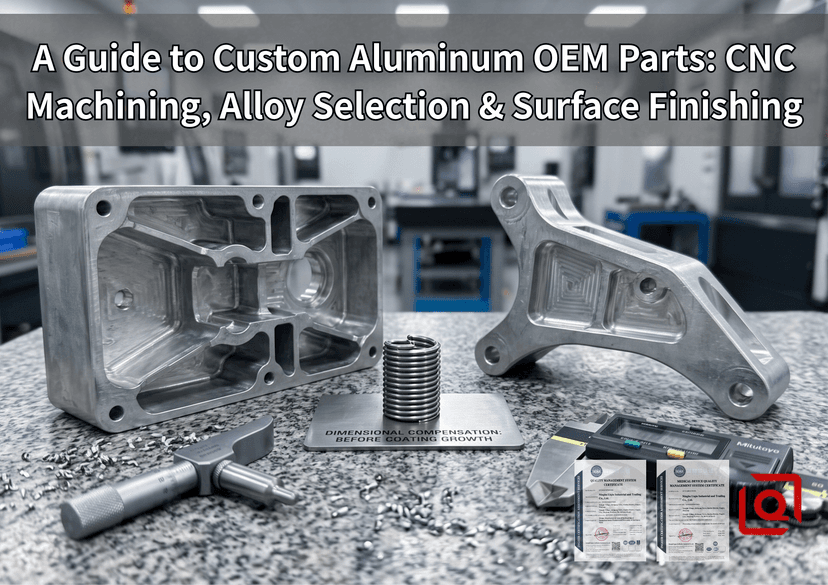
Whenever an OEM print hits my bench, nobody here asks whether a cutter can chew through it. What really keeps you guessing is how that raw stock behaves once trapped stresses let go at 12,000 RPM. We hog out aluminum daily for custom chassis, sensor mounts, robotic wrists, and manifolds because the alloy sheds heat fast, drops weight without losing backbone, and takes surface prep cleanly. Still, holding tenths takes far more than just pegging your spindle. Out by the machine, you learn the hard way: track thermal growth, back off the vise torque so thin ribs don't warp, dial in your feed rates for clean finishes, and leave enough meat for coating growth.
1. Alloy Selection: Matching Metallurgy to Functional Demands
Calling out generic "aluminum" without locking down temper codes practically begs for warped dimensions, bird-nested chips, or early corrosion failures on your parts.
-
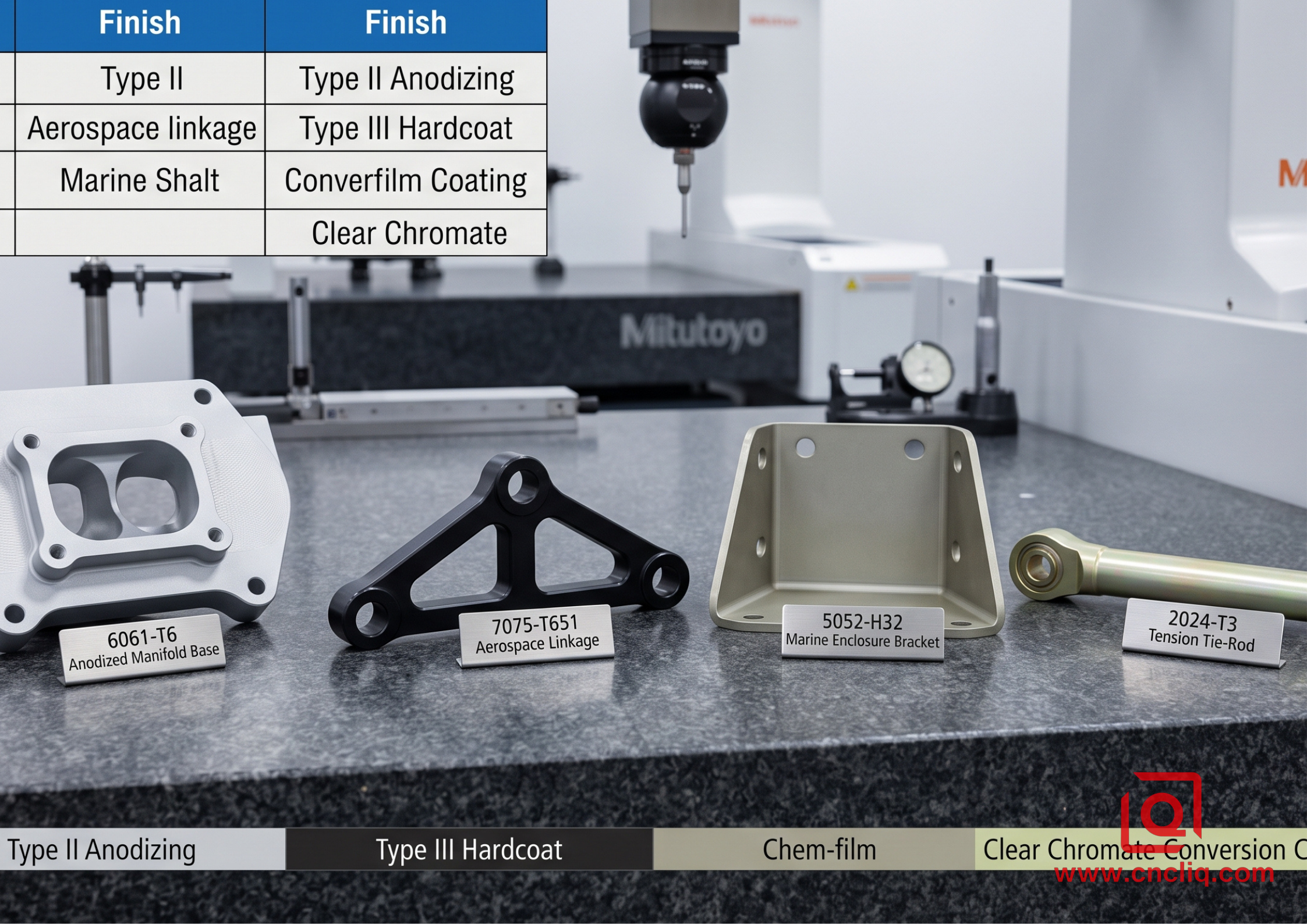
6061-T6 (The Go-To Default): Magnesium-silicon mix that cooks down into a predictable, forgiving material. It welds cleanly, holds its shape, and takes Type 2 sulfuric anodizing with zero fuss. Unless you are chasing extreme sub-zero loads or brutal cyclic stress, stick here to keep spindle time and raw material costs low.
-
7075-T651 (When Pure Strength Counts): Zinc-loaded and stretched to dump trapped tension. With a yield topping 500 MPa, this matches structural mild steel at roughly 40% of the weight. We run this for flight-critical mounts, high-pressure manifolds, and defense housings, though you will want a tough hardcoat or passivation to stop rust-like pitting in wet field conditions.
-
5052-H32 (Formed Sheet & Marine Work): Work-hardened magnesium alloy that refuses to corrode around saltwater spray. It acts gummy under an end mill when hogging deep pockets, but nothing beats it for stamped chassis, brake-formed brackets, and welded fluid tanks.
-
2024-T3 (Built for Cyclic Pull): Copper-heavy grade tuned for fracture toughness and relentless tension cycles. It remains our top pick for shear webs, tension tie-rods, and aerospace fittings. Just get Alodine or Chem Film on it right off the machine before galvanic attack starts eating the raw surface.
| Alloy Grade & Temper | Tensile / Yield Strength (MPa) | Machinability Index (%) | Primary Post-Finish Compatibility | Ideal OEM Applications |
| 6061-T6 | 310 / 275 | 90% | Type II/III Anodize, Powder Coat, Chem Film | Structural brackets, robotics housings, sensor enclosures |
| 7075-T651 | 570 / 505 | 70% | Type III Hardcoat, Clear/Yellow Chromate | Aerospace structural lugs, high-stress gears, test fixtures |
| 5052-H32 | 230 / 195 | 55% | Chem Film, Liquid Paint, Marine Anodize | Marine instrument chassis, deep-drawn enclosures, sheet brackets |
| 2024-T3 | 470 / 325 | 75% | MIL-DTL-5541 Chem Film, Cadmium / Zinc-Nickel | High-fatigue linkages, tension members, military fittings |
2. CNC Machining Strategies on the Shop Floor
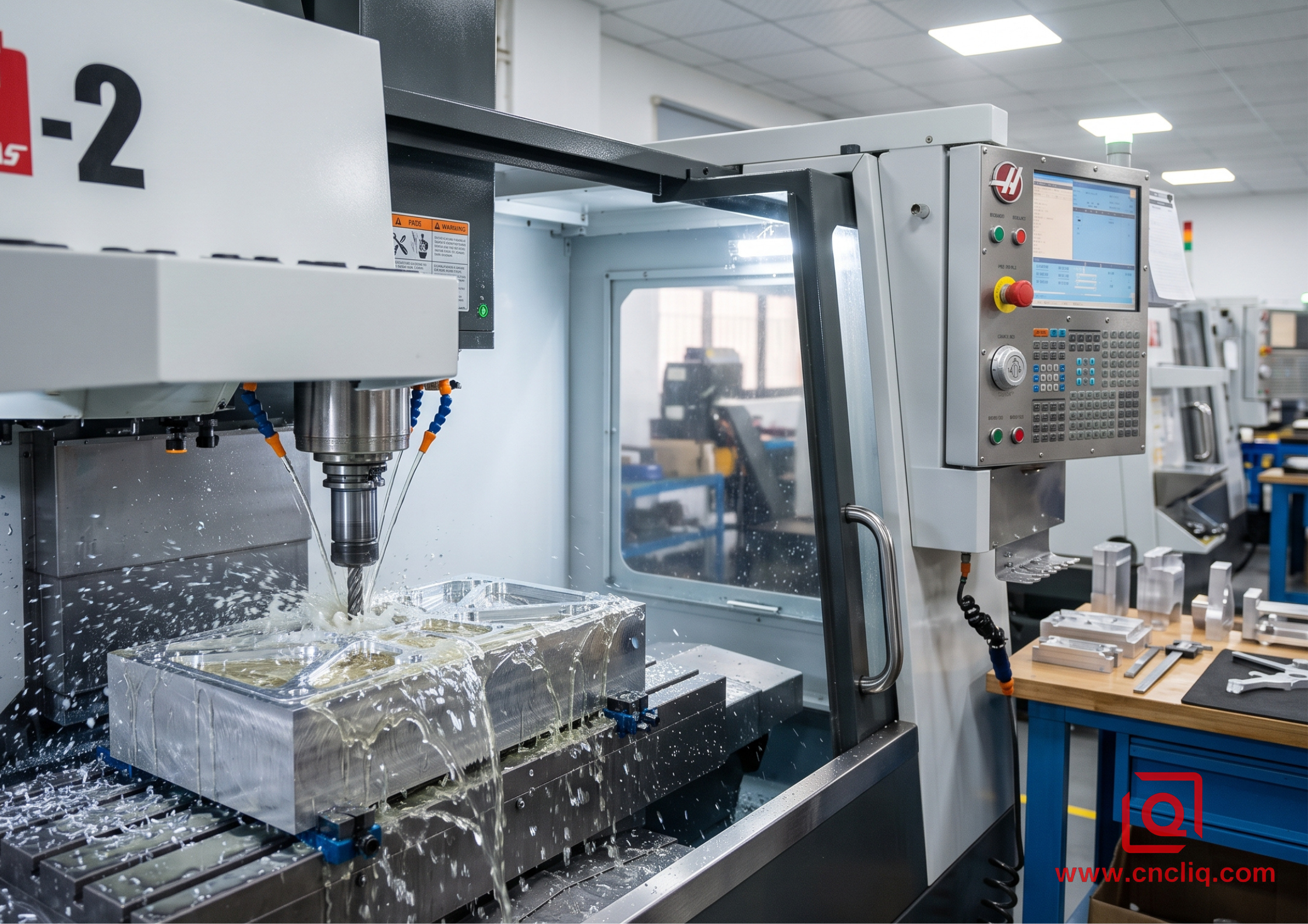
Turning raw billet into a tight-tolerance part demands control over heat buildup, tool deflection, and vibration. When cutting 6061-T6 on a 4-axis or 5-axis vertical machining center (VMC), we run high-helix 3-flute carbide end mills with polished flutes (ZrN or DLC coated) to prevent aluminum from galling and building up on the cutting edge (BUE).
Speed, Feed, and Chip Clearing Dynamics
For pocket roughing in 6061-T6, maintain surface speeds between 450 and 750 m/min, paired with a chip load of 0.08 to 0.18 mm/tooth. Never dwell in the cut. Dwell generates localized thermal friction, work-hardens the immediate shear zone, and causes thermal expansion that will warp thin floor plates once coolant flow stops. Flood high-pressure coolant (minimum 20 to 70 bar through-spindle) directly at the cut interface to blast chips out of deep cavities. Recutting chips is the fastest way to ruin a Ra 0.8 µm surface requirement.
Clamping and Stress Relief Protocols
Clamping a solid billet with hydraulic vise pressure at 25 kN will deform raw stock before the tool even makes contact. Once roughing cuts clear out 70% of the internal metal volume, residual extrusion stresses release unevenly. If you finish the part in that same clamping setup, the component will bow out of flat as soon as you open the vise jaws.
Our standard operating protocol for critical housings:
-
Stage 1: Bulk Roughing. Machine all external reference datums and rough out deep cavities, leaving 0.5 mm stock on all critical features.
-
Stage 2: Stress Release. Loosen all vise jaws completely. Allow the partially machined blank to restabilize at ambient room temperature (20 °C ± 1 °C).
-
Stage 3: Secondary Low-Pressure Fixturing. Re-clamp the component using custom soft jaws with torque limited to 6 to 8 Nm, applying vacuum chucking where thin base floors risk clamping distortion.
-
Stage 4: High-Speed Finishing. Execute finish passes with balanced finishing cutters at 15,000 RPM, taking shallow radial step-overs (0.10 to 0.25 mm) to hold ISO 2768-m or tighter geometric tolerances (GD&T profile of a surface within 0.025 mm).
3. Surface Finishing: Calculating Dimensional Compensation
A common breakdown between design prints and physical delivery happens during the finishing phase. Picture a customer print calling for a 28.000 mm (+0.008 / -0.000 mm) finished bearing seat, tagged with 50 µm of MIL-A-8625 Type 3 hardcoat. Hit nominal 28.004 mm on your boring head before shipping it out to the anodizer, and congratulations—you just bought yourself expensive scrap. Hardcoat does not behave like thin paint; it grows outward in a dead-reliable pattern that shrinks internal IDs fast.
-
The 50/50 Penetration Rule: Anodizing converts parent metal into an aluminum oxide crust rather than merely sitting on top.
-
Type 2 (Standard Decorative / Corrosion): Layer depth runs 8 to 15 µm. Since half penetrates down and half stacks upward, you will see your raw diameters shift outward or inward by roughly 8 to 15 µm across the full circle.
-
Type 3 Hardcoat (Wear Armor): Specs run anywhere from 25 to 50 µm per face. Dialing in a 50 µm coat means 25 µm of true outward growth on each wall. On an internal bore, that closes your final size down by a massive 50 µm across the diameter, while blowing an OD pin outward by that exact same 50 µm.
Machined Bore Target = Final Print Bore + (2 × Anodize Growth per surface)
Machined Pin Target  = Final Print Pin  - (2 × Anodize Growth per surface)
For threaded holes (e.g., M4x0.7 or M6x1.0), standard taps will result in tight, binding threads after 35 µm hardcoating. We deploy oversized CNC thread mills or 6H/6G oversized taps pre-calculated to clear thread pitch requirements after final oxide growth and hot-nickel-acetate sealing.
Chemical Conversion (Chromate / Chem Film per MIL-DTL-5541)
When parts require electrical grounding and paint adhesion without dimensional growth, specify MIL-DTL-5541 Type II Class 3 (RoHS clear/yellow film). Coating thickness is under 1 µm, requiring zero CNC pre-compensation.
4. Application Breakdown: Multi-Cavity Radar Enclosure for Industrial Automation
An international client in the factory robotics sector approached us to manufacture a multi-cavity, hermetically sealed sensor-and-radar transceiver chassis. The part required 7075-T651 billet machining, severe wall-thickness transitions down to 1.2 mm, strict sealing gasket surface finishes, and full weatherproofing.
+-----------------------------------------------------------------------------------+
| CASE SUMMARY: 7075-T651 ROBOTIC SENSOR HOUSING                                     |
| Part Dimensions: 240 mm × 165 mm × 48 mm from solid billet                        |
| Critical Tolerances: Bore true position 0.015 mm, Base flatness 0.020 mm          |
| Cavity Wall Thickness: 1.20 mm ± 0.05 mm across a 38 mm pocket depth              |
| Sealing Groove Spec: Ra 0.4 µm continuous toolpath; No cutter dwell marks         |
| Surface Callout: Dual-finish (Type III Hardcoat Black body + Chem Film cavity)    |
+-----------------------------------------------------------------------------------+
Shop-Floor Roadblocks & How We Cut Them
-
Taming Thin-Rib Sing: Pocketing down 38 mm while hugging 1.2 mm ribs practically invites severe chatter. We clamped down on vibration using adaptive trochoidal toolpaths paired with 4-flute, variable-pitch, variable-helix endmills, keeping cutter engagement locked dead at 18 degrees throughout the roughing cycle. We applied paraffin-based damping wax to the reverse cavity during final passes to eliminate vibration.
-
Dual Surface Finishing: The customer required deep internal antenna pockets to retain electrical conductivity (MIL-DTL-5541 Chem Film), while external mounting faces required 40 µm Type III Hardcoat Anodizing. We pre-machined external datums with -0.040 mm offset compensation, executed precision CNC custom masking plugs for internal cavities, and passed 240 hours of ASTM B117 salt spray testing with zero corrosion or flange distortion.
-
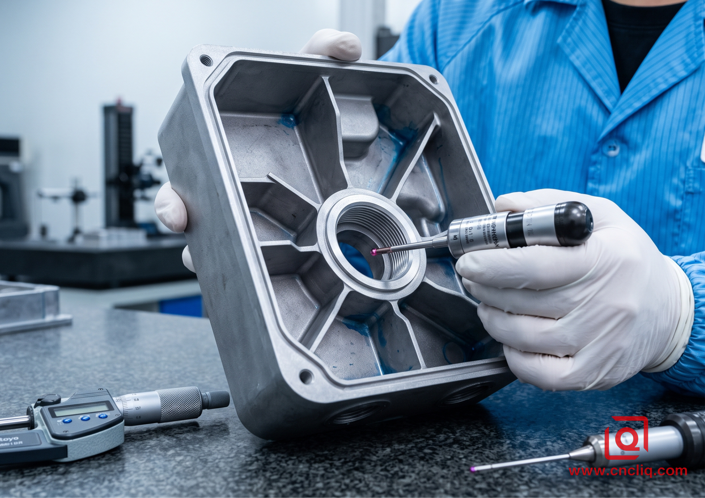
Final Metrology: 100% of parts passed on our 3-axis CNC Coordinate Measuring Machine (CMM) with Renishaw SP25M scanning probes, achieving 0.012 mm true position on bearing centers and Ra 0.32 µm finish across all O-ring sealing channels.
5. Straightforward DFM Guidelines for Custom Aluminum Sourcing
If you want to keep piece costs in check and avoid blown delivery dates, stick this rule to your monitor:
- Size Internal Corner Radii for Real Endmills: Never call out a pocket corner radius that dead-matches your cutter radius. Give us breathing room (like specifying R3.5 mm when we hog with a 6 mm tool). That keeps the machine sweeping through smooth arc moves rather than slamming the brakes at sharp 90-degree corners.
- Avoid Deep Pockets Exceeding 4x Tool Diameter: Deep cavities require long-reach end mills, which forces conservative feed rates to manage deflection. Keep pocket depth within 3 to 4 times corner tool diameter whenever feasible.
- Be Honest with Surface Finish Specs: Slapping Ra 0.4 µm across the whole print just bleeds spindle time and forces needless hand-polishing. Lock down Ra 0.4 µm strictly for bearing seats and seal lands; let raw clearance faces sit happily at Ra 1.6 to 3.2 µm.
- Tag Plating Growth Upfront: Spell out right on the title block whether bore tolerances hold BEFORE COAT or AFTER COAT. This single note prevents 90% of cross-border manufacturing disputes.
Dialing in custom aluminum parts boils down to one simple truth: you have to treat grain structure, tool loading, and surface bath chemistry as connected pieces. Speak the exact same shop language with your machinist, and those tight-tolerance prints stop being wishful thinking.
FAQs
Q1: How do you prevent internal thread binding after Type III Hardcoat Anodizing?
A: Hardcoat adds 15–25 µm per surface, shrinking thread pitch diameters by 60–100 µm. We resolve this by running oversized 6G/7G taps, programming CNC thread mills with pre-calculated radial offsets, or installing stainless steel Helicoil inserts after anodizing.
Q2: How do you eliminate warpage in asymmetric, thin-walled aluminum housings?
A: Our shop floor swears by a no-nonsense 4-step playbook: hog out the bulk leaving 0.5 to 1.0 mm of meat, unclasp the vise jaws entirely and let that stock rest for 4 to 8 hours, clamp down lightly in soft jaws or vacuum fixtures torqued under 8 Nm, then skim off final passes below 0.20 mm stepover.
Q3: 6061-T6 vs. 7075-T651: Which is better for outdoor enclosures?
A: Use 6061-T6. While 7075-T651 offers higher yield strength (505 MPa vs. 275 MPa), its copper and zinc content make it prone to corrosion and stress cracking outdoors. 6061-T6 provides superior weather resistance, better anodizing consistency, and 25–35% lower total cost.
Q4: Can tight bearing bores hold an ISO H7 tolerance after anodizing?
A: Yes. We pre-bore the feature 10–12 µm oversize before standard Type II anodizing to offset the inward growth. For tolerances tighter than 0.008 mm, we mask bores with precision silicone plugs prior to plating or perform a secondary post-anodize diamond reaming step.
Q5: What inspection paperwork actually rides along inside every custom aluminum shipment?
A: We never crate parts out the door without a full cert pack: raw mill EN 10204 3.1 MTRs, probed CMM dimensional and GD&T hits, ASTM B244 eddy-current coating thickness readings, ASTM B117 salt spray chamber slips, and verified profilometer Ra traces.
Summary
Pulling off repeatable aluminum OEM runs means keeping alloy makeup, cutter behavior, and plating tank chemistry locked in step. Pick your stock wisely—whether that is all-around 6061-T6 or brute-strength 7075-T651—step through proper setup relax cycles on the table, and factor in anodize growth before your tool touches metal. When prints spell out clean DFM rules upfront, you dodge dimensional drift, skip painful scrap piles, and turn CAD models into dead-accurate parts on the first go.
Contact Information
Disclaimer
All technical articles, material specifications, machining recommendations, and surface treatment details published on this blog are for informational and reference purposes only. Please note that general blog insights do not replace signed technical agreements. Because custom parts vary by material heat numbers, machine calibrations, and specific tolerances, binding quality specs are governed solely by your approved CAD drawings, signed contracts, and formal quality plans.
All customer case studies featured on this blog have been thoroughly anonymized and sanitized. The performance metrics, manufacturing workflows, and imagery displayed serve solely to demonstrate our custom machining capabilities and do not represent a single universal standard for all orders.
Liqin Manufacturing Team
Built on 18 years of precision engineering experience, Ningbo Liqin Industry manufactures high-tolerance metal components for demanding global markets. We operate out of a 6,500 m² production hub equipped with over 150 machines, running 4-axis and 5-axis CNC machining, mill-turn machining, cold extrusion, and pressure die casting under one roof. This setup allows us to manage projects seamlessly, taking parts from initial CAD concepts directly to finalized shipments.
We handle quality control with zero compromise. We treat tight tolerances with the engineering discipline they require. Backed by ISO 9001, ISO 13485, and IATF 16949 certifications, our QA engineers run strict IPQC, FQC, and OQC checks on every single production batch. From CMM dimensional mapping and optical profiling to hardness and salt-spray testing, we validate your critical specs upfront—so you receive drop-in ready components with zero assembly headaches or costly line stoppages. On top of manufacturing, you can rely on us for two-hour response times on new RFQs, direct support for prototype sampling, and smooth export shipping across Europe, North America, Asia, and Oceania.
Welcome your inquiries and samples. Visit our website or contact us directly for a competitive quote!
