 English




If you are an overseas procurement manager, a hardware engineer, or a manufacturing practitioner, you already know the stakes: a variance of just a few microns can turn a critical batch of aerospace shafts, medical implants, or electronic connectors into expensive scrap.
In modern manufacturing, precision turning has evolved from a basic machining operation into a highly controlled discipline where equipment capabilities, tool geometries, thermal dynamics, and material behaviors must be perfectly synchronized. This guide breaks down the core technical architecture of precision turning, providing actionable insights and Design for Manufacturing (DFM) strategies to optimize your production and clear up common supply-chain hurdles.
1. Fundamentals: What Separates "Precision" From "Ordinary" Turning?
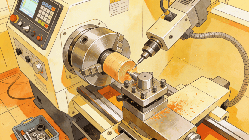
At its core, turning relies on the classic mechanical principle of workpiece rotation combined with tool feed. The spindle rotates the raw material while a single-point cutting tool shears away stock along a calculated linear or radial path.
However, when a shop transitions from ordinary turning to precision turning, the process undergoes a massive technical shift:
-
Dimensional Tolerances: Ordinary turning generally targets tolerances around IT9 to IT11 (tenths of a millimeter). Precision turning routinely hits IT6 to IT8, often holding dimensions within ±5 microns or tighter.
-
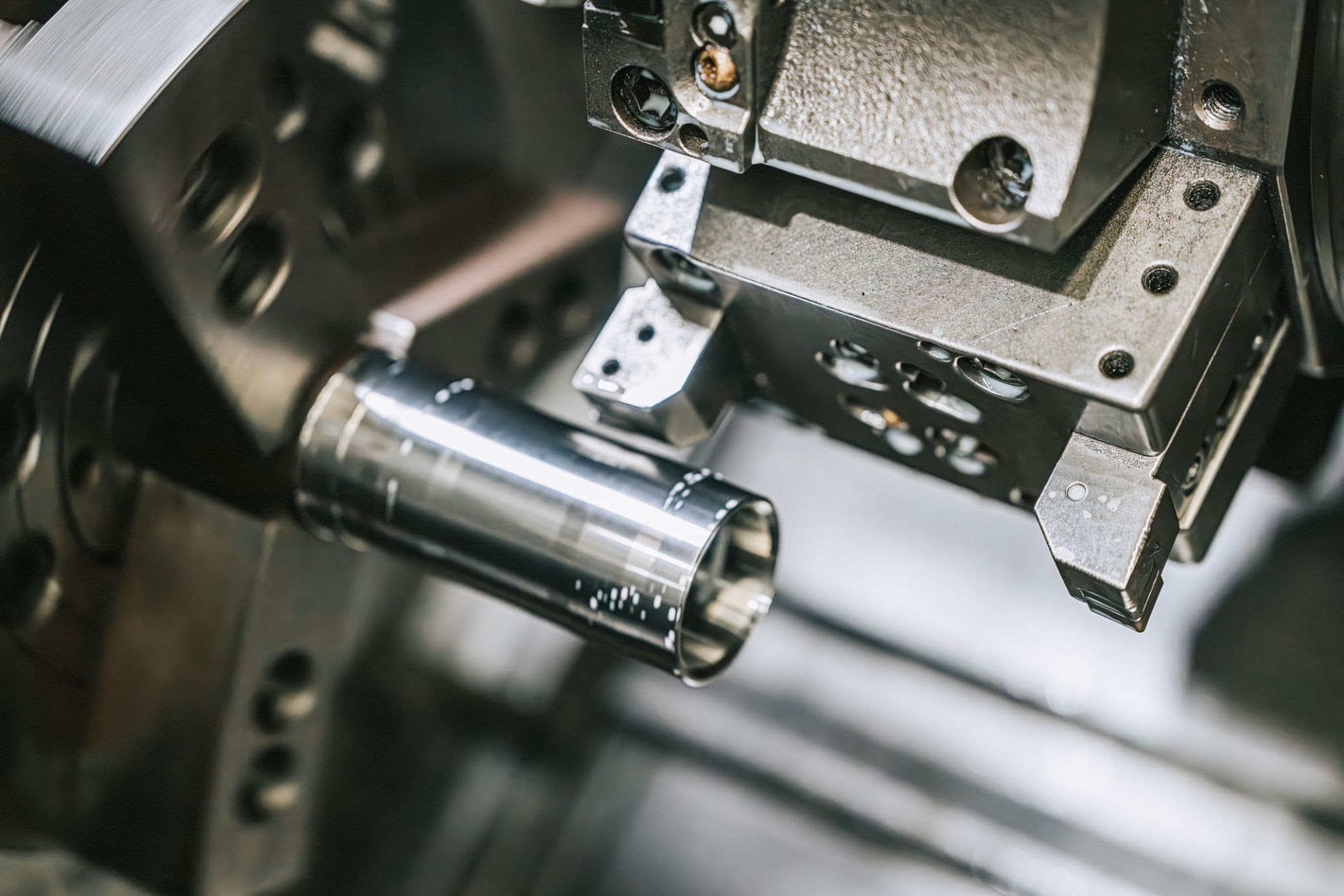
Surface Morphology: Rather than leaving distinct, visible feed marks, precision turning yields mirror-like surface finishes between Ra 0.8 μm and Ra 0.1 μm. This completely removes the need for secondary grinding or manual polishing in high-end applications.
-
Geometric Determinism: True precision requires managing the hidden variables. Spindle runout dictates your roundness; lead-screw resolution controls your linear dimensions; and clamping rigidity prevents part deflection during the cut. If any of these three pillars fail, precision disappears.
2. The Tooling & Machine Ecosystem
Your choice of hardware and consumables directly sets the ceiling for what your production line can achieve. Let's look at the actual tool and machine choices that drive a successful project.
2.1 Machine Configurations
Choosing the right machine layout depends entirely on part complexity and production volume:
2.2 Tool Substrates and Cutting Geometries
When selecting a tool material, you are balancing hardness, wear resistance, and impact toughness.

-
Micro-Grain Carbide: The absolute workhorse for precision turning. It balances excellent edge retention with enough toughness to handle minor micro-interruptions.
-
Cubic Boron Nitride (CBN): Second only to diamond in hardness. Essential for hard-turning steels (above HRC 50) where carbide tools would dull within seconds.
-
Polycrystalline Diamond (PCD): The premier choice for non-ferrous alloys (like high-silicon aluminum) and abrasive polymers. It maintains an incredibly sharp edge radius, reducing cutting forces to prevent thin-wall deflection.
2.3 Workholding Dynamics and Thermal Control
Clamping a part for precision work requires a gentle yet unyielding grip.
-
Thin-Walled Components: Standard 3-jaw chucks exert concentrated radial forces that ovalize thin tubes. For these applications, we swap to segmented collets or custom-machined pie jaws to distribute clamping pressure over a full 360 degrees.
-
Slender Shafts: Any part with an aspect ratio (Length-to-Diameter) greater than 4:1 will deflect under tool pressure. We mitigate this using live centers or steady rests to support the workpiece.
-
Thermal Management: Cutting creates immense localized friction heat. If left unmanaged, the part expands during the cut, only to shrink out of specification once it cools on the inspection bench. Precision setups use synthetic cutting fluids or high-pressure coolant (HPC) systems delivered directly at the tool tip to sweep away heat and evacuate chips immediately.
3. Core Operational Techniques
Every rotational feature requires a tailored toolpath strategy. Precision turning is rarely just about cutting a straight cylinder.
-
Boring and Internal Work: Internal holes are prone to tool deflection because the boring bar must overhang from the turret. To combat chatter, engineers use solid carbide boring bars (which have three times the rigidity of steel) and program conservative depths of cut.
-
Profiles, Taper, and Radii: Executing continuous contours requires seamless interpolation from the CNC control. To prevent micro-stepping textures along a radius, toolpaths should use constant surface speed (CSS) modes so the spindle automatically accelerates as the tool cuts closer to the centerline.
-
Threading Operations: Threading exerts high, intermittent forces on the tool edge. Multi-pass threading routines should employ a modified flank infeed strategy, cutting on a single side of the thread form to smoothly roll up chips and prevent thread-crest chipping.
4. End-to-End Workflow & Stratified Machining Strategy
To hit micron tolerances reliably across thousands of parts, a shop must implement a strict, multi-stage manufacturing sequence.
[Drawing & DFM Audit] ➔ [Stress-Relieved Blank Prep] ➔ [Roughing Stage] ➔ [Semi-Finishing] ➔ [In-Process OMM Probe] ➔ [Finishing Pass]
4.1 Stratified Machining: Roughing to Finishing
Never try to reach a final dimension in a single pass. Material yields and shifts when its outer skin is cut away.
-
Roughing: Maximize material removal rates (MRR) using heavy depths of cut (1.5 mm to 3.0 mm). This stage purposely releases internal material stresses and creates a predictable baseline.
-
Semi-Finishing: Cleans up the rough steps, leaving a uniform stock allowance (typically 0.2 mm to 0.4 mm) for the final pass. This ensures that the finishing tool encounters constant, predictable cutting pressure.
-
Finishing: Uses high spindle speeds, fine feeds (0.05 mm/rev to 0.1 mm/rev), and a shallow depth of cut to achieve the target surface roughness and final micron-level dimension.
4.2 On-Machine Measurement (OMM) & Compensation
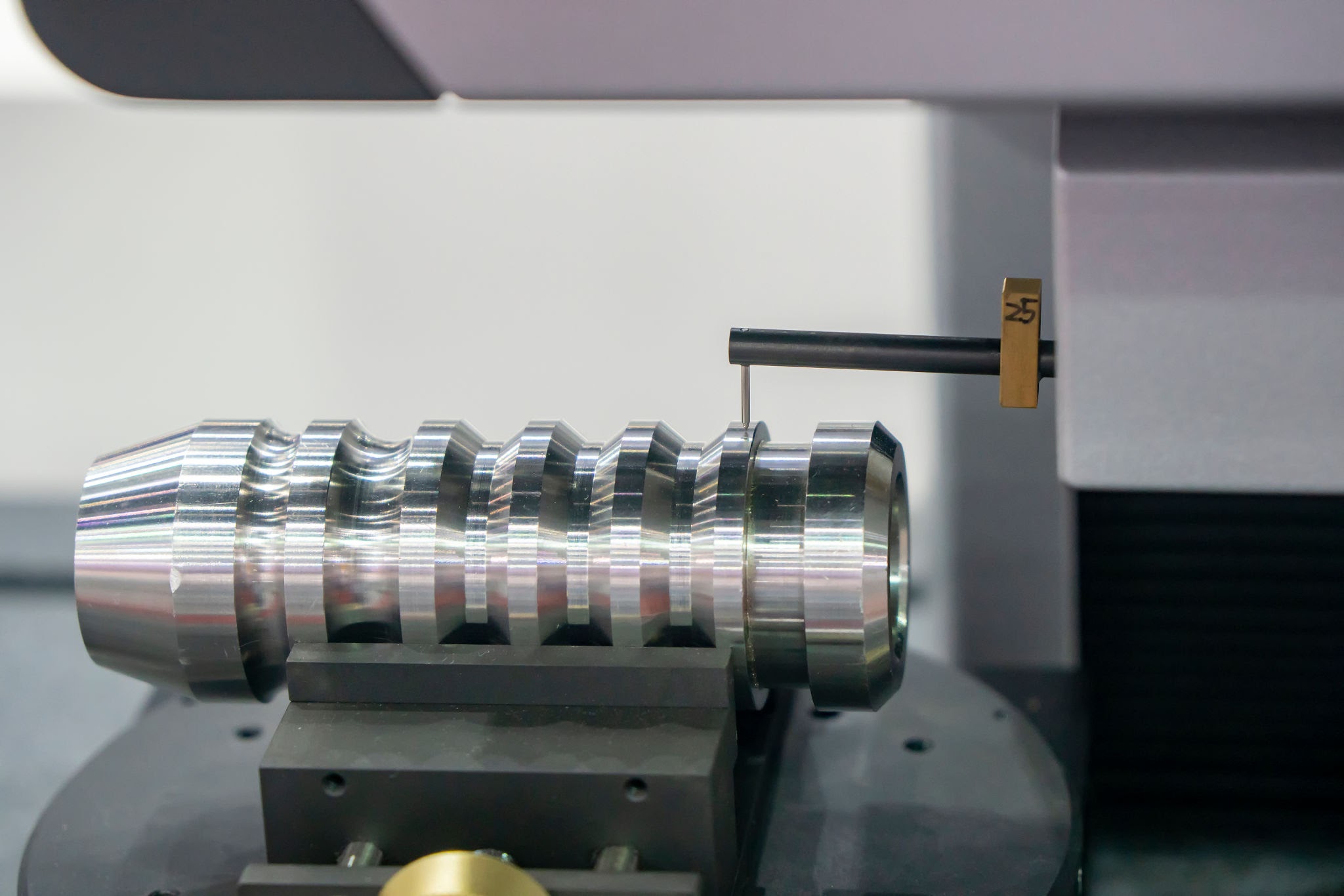
Even the best machines experience thermal drift as the shop floor temperature changes throughout the day. High-end turning operations integrate automated radio-frequency probes directly into the tool turret. The machine stops mid-cycle, probes a critical reference feature, calculates the exact tool wear offset, and dynamically updates its coordinate system before executing the final finishing pass.
5. Material Optimization & Technical Parameters
Different metals require completely unique cutting strategies. Below is a validated engineering guide matching materials with real-world machining data:
6. Troubleshooting Guide: Defects and Engineering Fixes
When parts fall out of spec, use this troubleshooting matrix to quickly diagnose and correct the root cause:
7. Real-World Case Studies
Case Study 1: Aerospace Titanium Hydraulic Connector
-
Material: Titanium Ti-6Al-4V
-
The Challenge: Hold a ±0.008 mm outer diameter tolerance across a batch of 5,000 units while preventing severe tool degradation from localized heat.
-
The Solution: Executed on a multi-axis CNC lathe using premium PVD-coated carbide inserts. Implemented a 70-bar through-spindle high-pressure cooling system targeting the cutting zone.
-
The Result: Tool life extended by 240%, thermal expansion was entirely eliminated, and the final batch passed inspection with a 99.8% yield rate.
Case Study 2: Medical Grade Artificial Hip Joint Accessory
-
Material: 316L VM Medical Stainless Steel
-
The Challenge: Achieve a flawless surface finish of Ra 0.2 μm directly on the machine, entirely eliminating manual polishing stages which risk altering geometric roundness.
-
The Solution: Utilized a Turn-Mill center with custom toolpath optimization. Applied a specialized wiper insert geometry combined with a high-lubricity neat cutting oil.
-
The Result: Surface finish consistently averaged Ra 0.15 μm, completely bypassing the polishing line and shaving 35% off total production cycle times.
8. Buyer's DFM Guidelines: Optimizing for Cost & Quality
To get the best price and quickest lead times from an overseas manufacturing partner, integrate these Design for Manufacturing rules directly into your prints:
Rule 1: Avoid Over-Specifying Surface Finishes Do not label every surface with an Ra 0.4 μm callout if an Ra 1.6 μm finish is functional for non-mating areas. Tight surface finishes require slower feed rates and more frequent tool changes, which drives up processing costs.
Rule 2: Include Tool Relief Grooves for Mating Threads When designing a turned shaft that bottoms out against a shoulder, always design a thread relief groove at the junction. Forcing a turning tool to cut crisp threads perfectly flush against a vertical wall invites tool breakage and high scrap rates.
9. Procurement FAQ: Bridging the Communication Gap
Q: How can a shop guarantee dimensional consistency across a high-volume batch of 10,000+ pieces? A: Look for shops utilizing automated tool wear compensation systems, automated bar feeders, and in-line metrology stations. A robust Quality Assurance protocol should include real-time Statistical Process Control (SPC) charts to monitor CPK values, ensuring variations are caught long before they cross tolerance thresholds.
Q: Is it cost-effective to replace secondary cylindrical grinding with precision hard-turning? A: Absolutely. Modern CNC lathes utilizing CBN inserts can easily perform "hard turning" on materials up to HRC 62. This allows you to combine rough turning, heat treatment, and final precision finishing all within a single machine setup, dropping your material handling costs and cycle times significantly.
Q: How do you handle thin-walled parts to prevent chuck deformation? A: We use specialized workholding. Standard hard jaws are replaced with wrap-around pie jaws or custom pneumatic collets that spread the clamping force. We also optimize the toolpaths to cut toward the sturdiest section of the fixture, ensuring the part doesn't warp during machining.
Q: What document package should I expect from a precision turning supplier? A: For precision components, your shipment should always include a Material Test Report (MTR) verifying raw material chemistry, a Full Dimensional Inspection Report (often utilizing CMM data), and relevant compliance certificates (such as RoHS or REACH certifications).
Email: zhouli@chinaliqin.com
WhatsApp:+86 187 5714 8656
Website:https://www.cncliq.com/