 English




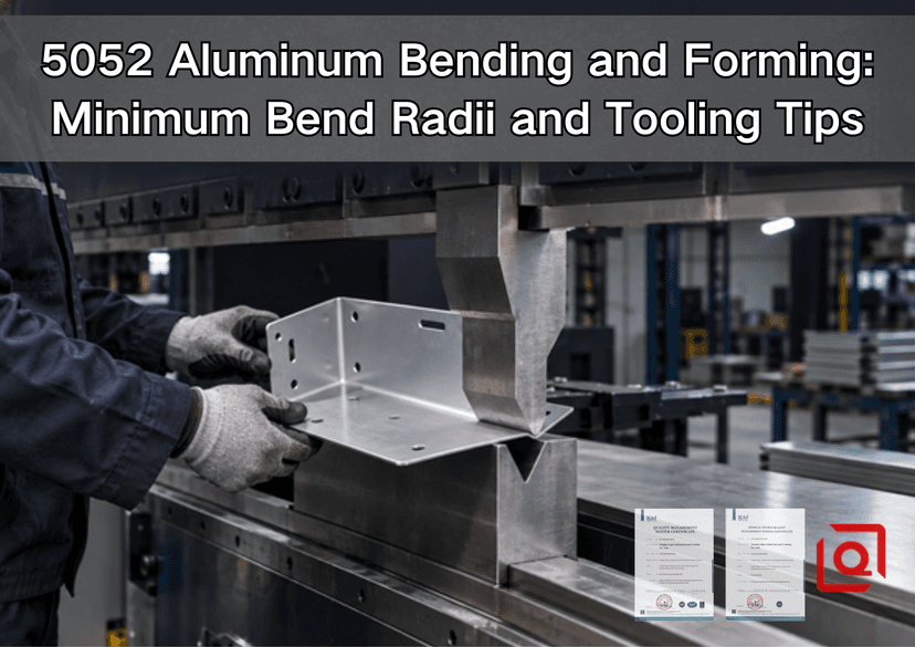
Have you approved a 5052 bracket, then found faint cracks at the bend or a flange that landed a millimeter away from print? I have seen both failures start with a drawing that looked perfectly sensible. 5052 forms well, certainly, but that description leaves out the grain, the die opening, and the way a real sheet relaxes when the ram lifts. We will work from the drawing to the brake and then to inspection. Along the way, you will see where to start with radius, tooling, springback, flat length, and surface protection. Buyers will also get a practical RFQ list, so the next quotation is based on an agreed process rather than a quiet assumption.
Quick Answer: What Minimum Bend Radius Should You Use for 5052 Aluminum?
For an ordinary 90 degrees cold bend in 5052-H32, put 1.0T to 1.5T on the first DFM sketch; T means the measured sheet thickness. That range is a starting benchmark, not a promise. Mill tables allow tighter work in thin H32 stock, yet one published table moves to roughly 1.5T at 3.2 mm. A change in temper, grain direction, cut edge, tool set, or material lot can shift the limit.
A bend drawn along the rolling direction deserves extra room because small surface splits appear there first. Rotate the blank so the line crosses the rolling direction when the nest permits it; otherwise open the radius. Before releasing a new part, bend one coupon cut from the production heat lot with the tools that will actually run the job.
|
5052-H32 sheet thickness |
Published 90 degrees minimum radius reference |
Conservative drawing start |
Shop-floor note |
|
0.4 mm |
0T |
0.5T to 1.0T |
A nominally sharp bend appears in mill data, but a small radius improves repeatability and appearance. |
|
0.8 mm |
0T |
0.5T to 1.0T |
Protect cosmetic faces from die-shoulder marks. |
|
1.6 mm |
1.0T |
1.0T |
A strong general starting point for brackets and covers. |
|
3.2 mm |
1.5T |
1.5T |
Confirm tonnage, minimum flange, and bend direction before release. |
|
Above 3.2 mm |
Confirm with supplier |
1.5T or larger pending trial |
Plate behavior depends strongly on temper, grain direction, tooling, and bend length. |
The published values above come from the Hulamin 5052 Data Sheet for 90 degrees cold forming. The conservative column is a drawing start, not a guaranteed capability. A zero-radius entry does not mean the metal becomes a mathematically sharp corner. The formed part will still have a physical radius, and forcing the outside fibers around a knife edge can leave a crease, thinning, or small cracks.
Why 5052 Is a Natural Choice for Formed Aluminum Parts
5052 belongs to the aluminum-magnesium family and cannot be strengthened by heat treatment. Rolling work hardens it; 6061-T6, by contrast, gains much of its strength through solution treatment and ageing. On a brake, that metallurgical difference is easy to feel. H32 stock will accept enclosure corners, tray walls, marine brackets, and welded seams that would be risky in a harder, less ductile grade.
Typical published physical properties include a density of about 2.68 g/cm3 and an elastic modulus near 70 GPa. Mill data also describes good cold formability, very good weldability, and very good resistance to seawater and industrial atmospheres. Mechanical values vary with thickness and governing specification, so the purchase order should call out the alloy, temper, product form, and material standard - commonly ASTM B209/B209M for aluminum sheet and plate - rather than simply saying "5052 aluminum."
The temper suffix matters. H32 means the sheet has been strain hardened and stabilized to a quarter-hard condition. H34 is harder and generally asks for a more generous radius. O temper is annealed and forms more easily, but it also has lower strength and can mark or distort more readily. Substituting one temper for another without drawing approval can change bend force, springback, flat length, and service stiffness.
For a wider comparison of 5052 with machining-oriented grades, see Liqin's guide to machining 6061, 7075, and 5052 aluminum. That article focuses on alloy behavior under a cutting tool; this guide stays with forming and the decisions around the bend line.
Minimum Radius Is a System Decision, Not a Material Number
A bend fails when the tensile strain at the outside surface exceeds what the real sheet can tolerate. The inside radius is important, but it is only one input. Before approving a 5052 forming drawing, review the following together:
- Temper and heat lot: H32, H34, and O temper do not share one safe radius. Even compliant lots have property ranges.
- Actual thickness: A nominal 2.0 mm sheet may not measure exactly 2.0 mm. The forming program and flat pattern should use an agreed thickness basis.
- Rolling direction: Tight bends are normally safer when the bend line is perpendicular to the rolling direction.
- Cut-edge condition: Burrs, rough laser edges, deep scratches, and corner notches can start a crack. Put the burr on the inside when practical and deburr before forming.
- Bend angle: A 30 degrees bend and a closed hem do not impose the same strain history as a 90 degrees bend.
- Process: Air bending, bottom bending, coining, wiping, roll forming, and deep drawing load the sheet differently.
- Tool wear and alignment: A damaged shoulder or mismatched tool segment can mark the sheet and twist the angle.
- Feature proximity: Holes, slots, tabs, and cutouts placed too close to the bend can stretch into ovals or pull the flange out of line.
This is why a buyer should be cautious when a quotation promises "1T for all 5052." A useful supplier response connects the proposed radius to the specified temper, measured thickness, bend direction, V-opening, punch nose, and inspection plan.
Grain Direction: The Cheapest Crack Prevention on the Drawing
Rolled sheet develops directionality. When a bend line runs parallel to the rolling direction, the outside fibers open along the elongated grain structure, which increases the chance of visible microcracking. Turning the blank 90 degrees makes the bend line cross the rolling direction and generally improves formability. The Atlas Aluminium 5052 datasheet also qualifies its recommended 90 degrees bend data by rolling direction.
That rotation can affect material yield, especially when a nest contains long rectangular panels. Do not let nesting efficiency quietly overrule a critical bend. Mark the rolling direction on the flat pattern, identify any bend that must cross the grain, and ask the fabricator to keep that orientation through cutting and forming. If blank rotation is impossible, increase the inside radius and validate a coupon before production.
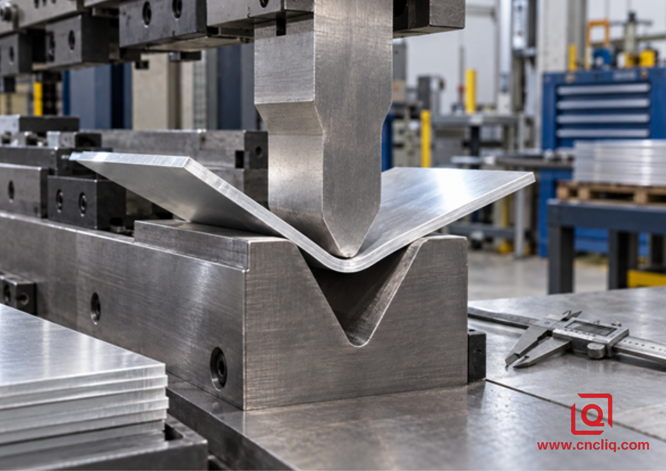
Figure 1. The bend comes from the complete setup: V-opening, punch, measured thickness, and the response of that sheet lot.
Air Bending Tool Selection for 5052-H32
Most job shops favor air bending: one punch and die can cover several angles, and the press uses less force than it would for bottoming or coining. During the stroke, contact occurs at 3 places - the punch nose and both die shoulders. The sheet never fills the bottom of the V. As a result, the released inside radius reflects the opening and the material response; it is not a stamped copy of the punch tip.
Start With the V-Die Opening
A V-opening near 6T to 8T is a practical place to begin for many 90 degrees air bends. The familiar "rule of 8" is only a tooling starting point. A narrower opening can support a shorter flange and produce a tighter bend, but force and surface pressure rise. A wider opening reduces force, yet it increases the natural radius, minimum flange length, and sensitivity to springback.
For mild steel, the Haas press-brake operation guide estimates the air-formed inside radius at about 16% of the V-opening, recommends a V-opening near 8T as a start, and places minimum flange length near 77% of V. Do not copy the 16% coefficient blindly into a 5052 program. Aluminum alloy and temper change the relationship. Use the brake/tooling supplier's aluminum chart, then verify the result on the actual sheet lot.
As a quick feasibility check, minimum flange length in conventional air bending is often around 0.7V to 0.77V, measured according to the chosen chart and geometry. If the model has a 7 mm flange but the intended die needs a 12 mm opening, the part may not sit safely on both shoulders. The answer might be a smaller V, a special tool, a redesigned flange, a staged operation, or a different forming method - not simply more ram travel.
Match the Punch Nose to the Planned Radius
A very sharp punch does not guarantee a sharp, controlled bend. If its nose is much smaller than the material can accept, it can concentrate pressure and leave a crease while the outer surface begins to tear. Select a punch nose compatible with the target inside radius and make sure its load rating exceeds the calculated force with a proper safety margin.
Gooseneck punches provide clearance for return flanges and box shapes. Straight punches are stiffer and preferable when the geometry allows them. Before production, simulate or physically check the bend sequence: a part can be individually bendable yet impossible to remove after the final flange closes around the tooling.
Protect Cosmetic Surfaces
5052 is relatively soft. Bare die shoulders can leave two witness lines that remain visible after anodizing or brushing. Clean the tooling, remove embedded steel particles, and consider urethane film or suitable protective tooling for appearance-critical faces. Protective film changes friction and may shift the angle slightly, so it belongs in the validated setup rather than being added halfway through a lot.
Springback: Program the Result, Not Just the Stroke
After the ram retracts, elastic strain recovers and the bend opens. That is springback. It increases with a larger R/T ratio, higher-strength temper, wider V-opening, and material variation. A controller may compensate by overbending, but the correction must be proven with the actual tool set and stock.
Avoid publishing one fixed statement such as "5052 always needs 2 degrees of overbend." A 75 mm coupon may spring back differently from a 900 mm enclosure wall. Begin with the brake library, make a trial hit, and measure only after the load is gone. Adjust penetration from that reading. Then save the working recipe together with the heat lot, thickness, grain direction, punch, die, and whether protective film was present.
For long bends, angle variation can come from machine and tooling deflection, not only springback. Crowning or segmented compensation may be required so the center of the bend matches the ends. Check angle at several positions instead of accepting one reading near the edge.
Bend Allowance, K-Factor, and Flat-Pattern Control
The outside stretches and the inside compresses during forming. Between them lies a neutral axis whose length changes much less. Flat-pattern software uses a K-factor to describe the neutral-axis position through the thickness.
For a bend angle A in degrees, inside radius R, material thickness T, and K-factor K:
Bend allowance, BA = (pi / 180) x A x (R + K x T)
Here is a layout check from the bench: 1.6 mm H32 sheet, a 1.6 mm inside radius, a 90 degrees bend, and a temporary K-factor of 0.40.
BA = (pi / 180) x 90 x (1.6 + 0.40 x 1.6) = 3.52 mm
The answer, 3.52 mm, belongs in a trial worksheet - not yet in a released production blank. The effective K-factor changes with tooling, R/T, friction, temper, and bend method. A sound launch process cuts a coupon of known length, forms it with the intended tools, measures the resulting flanges, and back-calculates the shop's bend deduction. Save that value in the material/tooling table and use it for the released flat pattern.
Do not mix a customer-generated flat pattern with a supplier's bend table without agreement. The cleanest RFQ states whether the provided DXF is authoritative or whether the manufacturer may regenerate the blank from the finished 3D model and controlled dimensions.
Holes, Slots, Reliefs, and Bend Sequences
Features near a bend sit inside a strain zone. A round hole can become oval; a slot may flare; an edge can pull inward. When design space allows, keep holes and slots at least R + 2T from the bend tangent. More clearance is useful for large holes, countersinks, cosmetic faces, and severe angles. If the feature must be closer, consider piercing or machining it after forming.
A bend relief stops the bend strain from dragging an adjacent edge. As a conservative starting geometry, use a relief width of at least 1T and a depth reaching at least R + T past the bend line. Round the end of the relief rather than leaving a sharp internal corner. The exact relief must suit the tool and visible-edge requirement.
Sequence also matters. Form short internal flanges before tall walls block tool access. Watch for collisions between previously formed legs and the punch holder. Where a milled boss, tapped hole, or precision face is added after forming, establish datums that reflect the assembled function. Liqin's overview of custom aluminum OEM process selection explains when secondary CNC work is worth adding instead of forcing every feature into the flat blank.
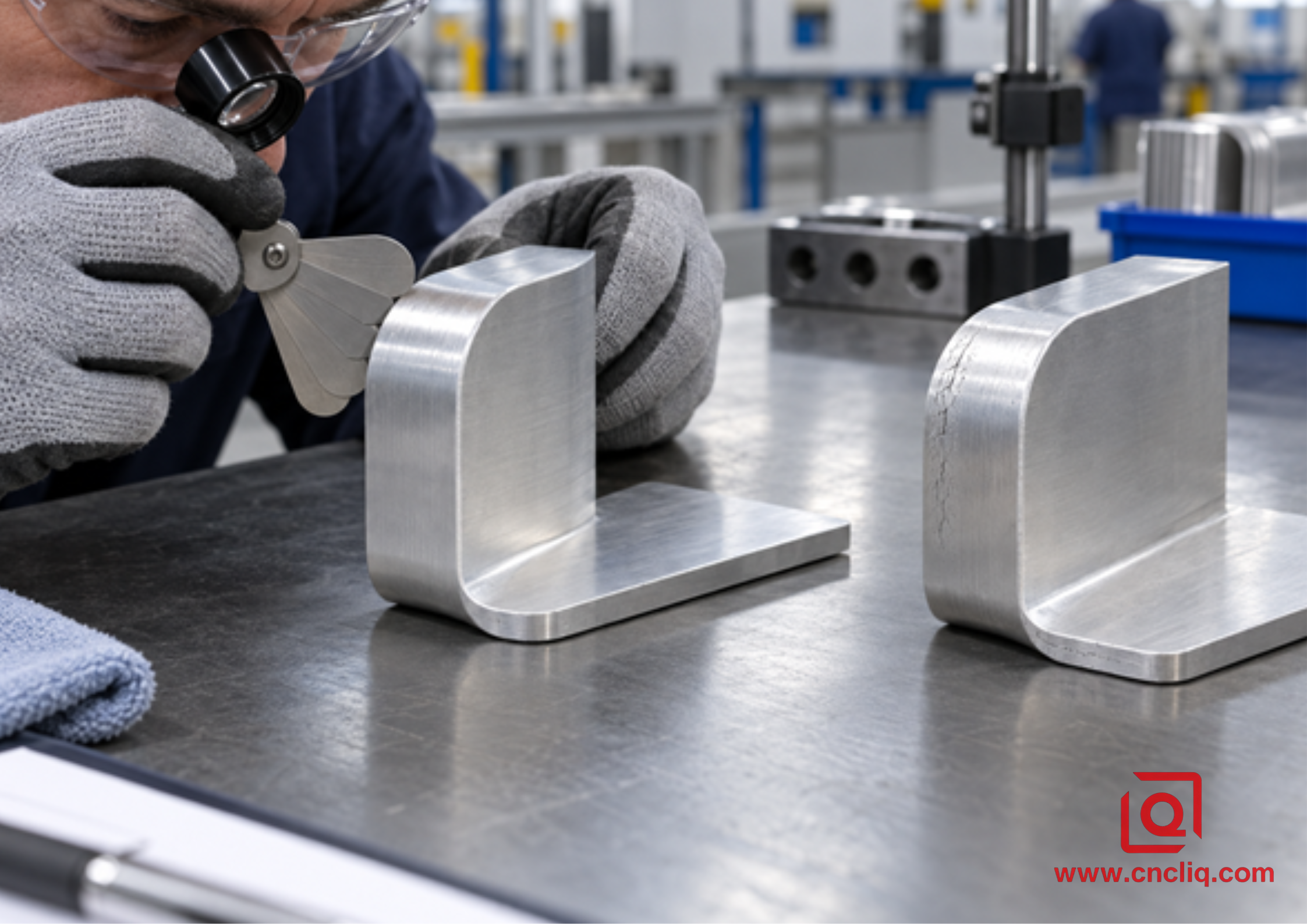
Figure 2. Tilt the outer radius under a bright lamp. Fine lines running with the bend often show up well before an obvious split.
Common 5052 Bending Defects and Practical Corrections
|
Symptom |
Likely cause |
Practical correction |
|
Fine cracks on the outside radius |
Radius too tight, bend with the grain, hard temper, rough cut edge, or damaged surface |
Rotate the blank, increase R, verify temper, deburr, and run a heat-lot coupon. |
|
Bend opens after unloading |
Springback not compensated or material lot changed |
Measure the free angle, adjust penetration or overbend, and lock the recipe to the tool and lot. |
|
Flange is dimensionally wrong |
Bend deduction does not match the actual process |
Back-calculate bend deduction from a coupon and regenerate the flat. |
|
Two bright lines on the cosmetic face |
High contact pressure or dirty die shoulders |
Clean and polish tooling, use approved protection, and retune for changed friction. |
|
Angle varies along a long bend |
Machine or tool deflection, uneven thickness, misalignment, or poor crowning |
Verify tool seating, inspect thickness, apply crowning, and measure at several stations. |
|
Hole or slot distorts |
Feature lies inside the bend strain zone |
Move it away, add relief, or finish the feature after bending. |
|
Part twists after several bends |
Unbalanced sequence, inconsistent gauging, grain effects, or accumulated angle error |
Replan the sequence, use stable gauging, control grain direction, and inspect intermediate stages. |
Anonymized Composite Case: 5052 Marine Electronics Enclosure
The following is an anonymized composite example created to show a realistic DFM workflow; it is not a claim about one named customer or a universal production result.
A European equipment buyer requested a 2.0 mm 5052-H32 electronics enclosure for a salt-air environment. The first drawing used a 1.0 mm inside radius, narrow return flanges, 4 slots close to bend tangents, and a cosmetic brushed face. The flat DXF had also been generated with a generic K-factor that was not tied to the proposed V-die.
During review, the manufacturing team treated the 0.5T radius as the first risk. The critical long bends were reoriented across the rolling direction, and the drawing radius was opened to 2.0 mm, or 1T. Two slots were shifted outside the strain zone; two functionally fixed openings were left undersize for secondary machining after forming. The return flange was widened so it could remain supported on the selected die shoulders. A rounded bend relief was added where the side-wall bend met an open edge.
The route covered material verification, blank cutting and deburring, coupon trials, flat-pattern correction, staged forming, secondary CNC work, surface preparation, and final inspection. The team used the coupon to establish the bend deduction instead of treating a handbook K-factor as final. Cosmetic faces remained protected through forming, and the inspection plan called for overall width, flange height, bend angle at several positions, slot location from formed datums, and a visual check of the outer radius.
Aligned CAD, tooling, and inspection datums prevent later disputes. If your part combines formed sheet with milled interfaces, Liqin's aluminum material and process guide provides useful context, while the CNC machining service page shows the broader custom-manufacturing route available for secondary features.
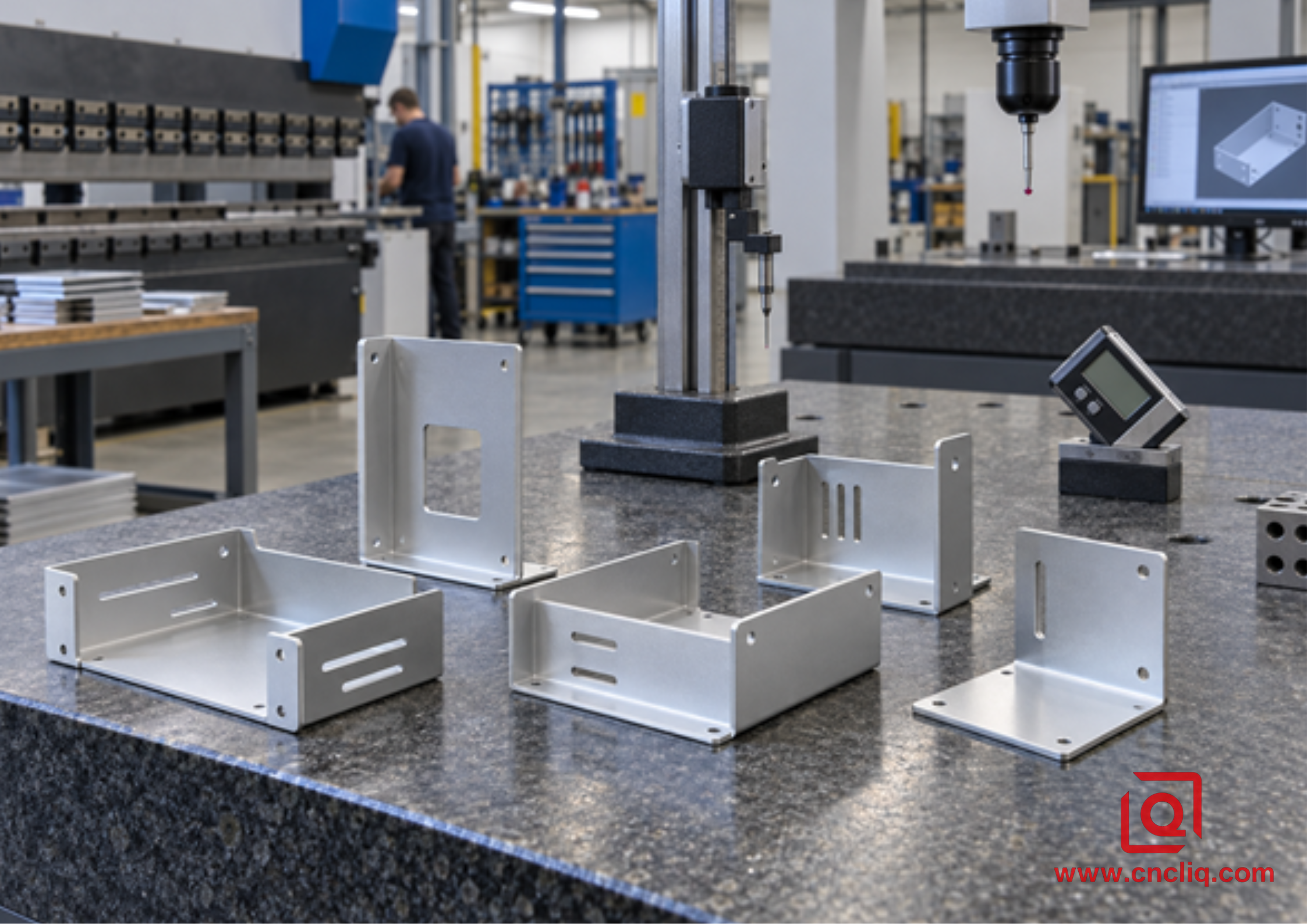
Figure 3. Check from the datums the assembly will use, and take angle readings at more than 1 spot.
What to Put in an RFQ for a Reliable 5052 Bending Quote
Send enough information for the supplier to evaluate the whole forming system. A strong RFQ package includes:
- A STEP model and a controlled 2D PDF drawing with revision level.
- Alloy, temper, thickness, and applicable material standard.
- Finished inside radius and angle; identify which dimensions are inspection-critical.
- Rolling-direction requirement on severe bends, if known.
- Flat-pattern authority: customer-controlled DXF or supplier-developed blank.
- Quantity for prototypes, validation lots, and annual demand.
- Surface finish, cosmetic side, masking needs, and acceptable tool marks.
- Hardware, welding, machining, and coating sequence.
- Required certificates, inspection report, packaging, and corrosion testing.
- Mating-part or assembly context for tight flange and hole-location tolerances.
State whether the bend radius is open to DFM adjustment or function-critical. For a fast technical review, send the STEP file, drawing, quantity, finish, and service environment through Liqin's contact page. Ask the supplier to confirm radius, V-opening, bend direction, flat-pattern ownership, and inspection method before the first batch.
FAQ
1. Can 5052-H32 be bent to a zero inside radius?
A mill chart can print 0T beside very thin H32, but read that entry carefully. It describes a test condition; it does not create an infinitely sharp corner. Push real sheet over a knife edge and you may trade an intact bend for a crease, a thin outer skin, or fine cracks. On a production print, I would normally keep a small positive radius and prove anything tighter on material from the actual heat lot.
2. Is 1T always safe for a 90 degrees bend in 5052-H32?
No - 1T is not a blanket approval. It often works, yet a harder temper, a scratched edge, a long bend, or an unfavorable grain can change the result. One mill guide moves to roughly 1.5T at 3.2 mm thickness. If the line must run with the rolling direction, or if the outside face is cosmetic, give the bend more room and trial it first.
3. What V-die opening should I use for 5052 aluminum?
Pull the available 6T and 8T dies first, then check what each choice does to the radius, short flange, force, and punch load. The familiar 16% rule grew from mild-steel practice, so it is not an exact promise for 5052. Let the brake maker's aluminum chart narrow the choice, and settle it with a coupon from production stock.
4. What K-factor should I enter for 5052-H32?
No single K-factor follows 5052 from one brake to the next. For an early 90 degrees air-bend layout, 0.40 is a reasonable placeholder. Do not freeze the DXF around it. Form a coupon with the planned punch, V-die, thickness, radius, and sheet lot; measure the flanges; then put the back-calculated deduction in the shop table. That measured value beats the CAD default.
5. What files and specifications help Liqin quote a formed 5052 part?
Provide a STEP model, controlled 2D drawing, alloy, temper, thickness, quantities, finish, cosmetic-face requirement, critical dimensions, and inspection needs. State whether your DXF flat pattern must be used or whether the manufacturing team may develop it. Mention welded or machined secondary features and the service environment so the process plan and quotation address the complete part.
Summary
5052-H32 is an excellent alloy for corrosion-resistant enclosures, brackets, trays, and welded sheet assemblies, but a reliable bend comes from a controlled system rather than one radius chart. The useful starting window for many 90 degrees bends is 1.0T to 1.5T. Put the bend across the grain when you can, choose punch and die together, and cut a coupon before locking the flat. Keep holes out of the strain zone, too. Send temper, thickness, finished geometry, cosmetic limits, quantity, and inspection needs with the RFQ; those details turn a hopeful radius into a repeatable part.
Contact Information
Company: Ningbo Liqin Industry Co., Ltd.Daily customer maintenance & after-sales support:service@shturl. zhuwanying@cncliq.com
New inquiry, quotation & order discussion:business@shturl. zhouli@chinaliq.com
Hotline: +86 18757148656
Disclaimer
All technical articles, material specifications, machining recommendations, and surface treatment details published on this blog are for informational and reference purposes only. Please note that general blog insights do not replace signed technical agreements. Because custom parts vary by material heat numbers, machine calibrations, and specific tolerances, binding quality specs are governed solely by your approved CAD drawings, signed contracts, and formal quality plans.
All customer case studies featured on this blog have been thoroughly anonymized and sanitized. The performance metrics, manufacturing workflows, and imagery displayed serve solely to demonstrate our custom machining capabilities and do not represent a single universal standard for all orders.
Liqin Manufacturing Team
Built on 18 years of precision engineering experience, Ningbo Liqin Industry manufactures high-tolerance metal components for demanding global markets. We operate out of a 6,500 m2 production hub equipped with over 150 machines, running 4-axis and 5-axis CNC machining, mill-turn machining, cold extrusion, and pressure die casting under one roof. This setup allows us to manage projects seamlessly, taking parts from initial CAD concepts directly to finalized shipments.
We handle quality control with zero compromise. We treat tight tolerances with the engineering discipline they require. Backed by ISO 9001, ISO 13485, and IATF 16949 certifications, our QA engineers run strict IPQC, FQC, and OQC checks on every single production batch. From CMM dimensional mapping and optical profiling to hardness and salt-spray testing, we validate your critical specs upfront - so you receive drop-in ready components with zero assembly headaches or costly line stoppages. On top of manufacturing, you can rely on us for two-hour response times on new RFQs, direct support for prototype sampling, and smooth export shipping across Europe, North America, Asia, and Oceania.
Welcome your inquiries and samples. Visit our website or contact us directly for a competitive quote!
