 English




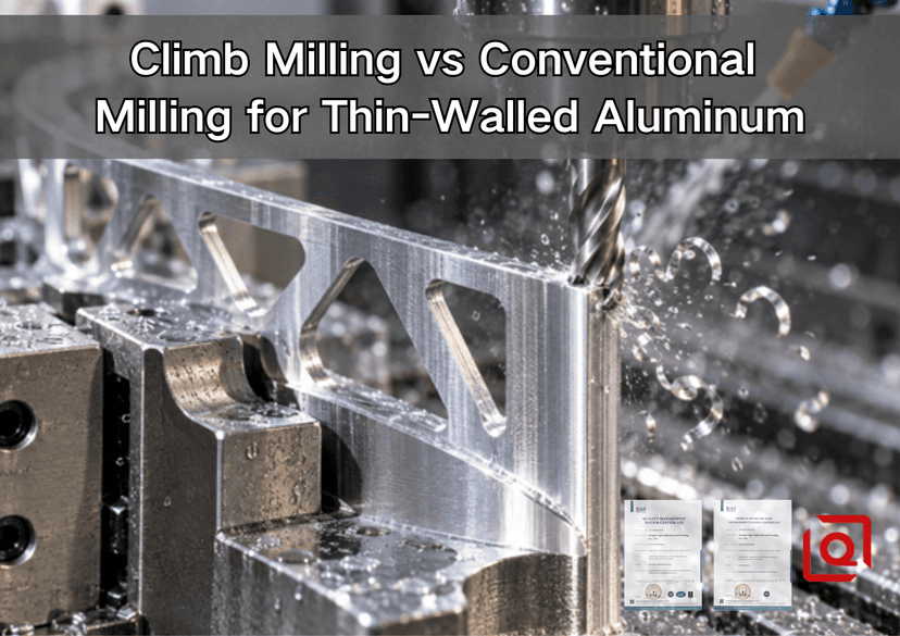
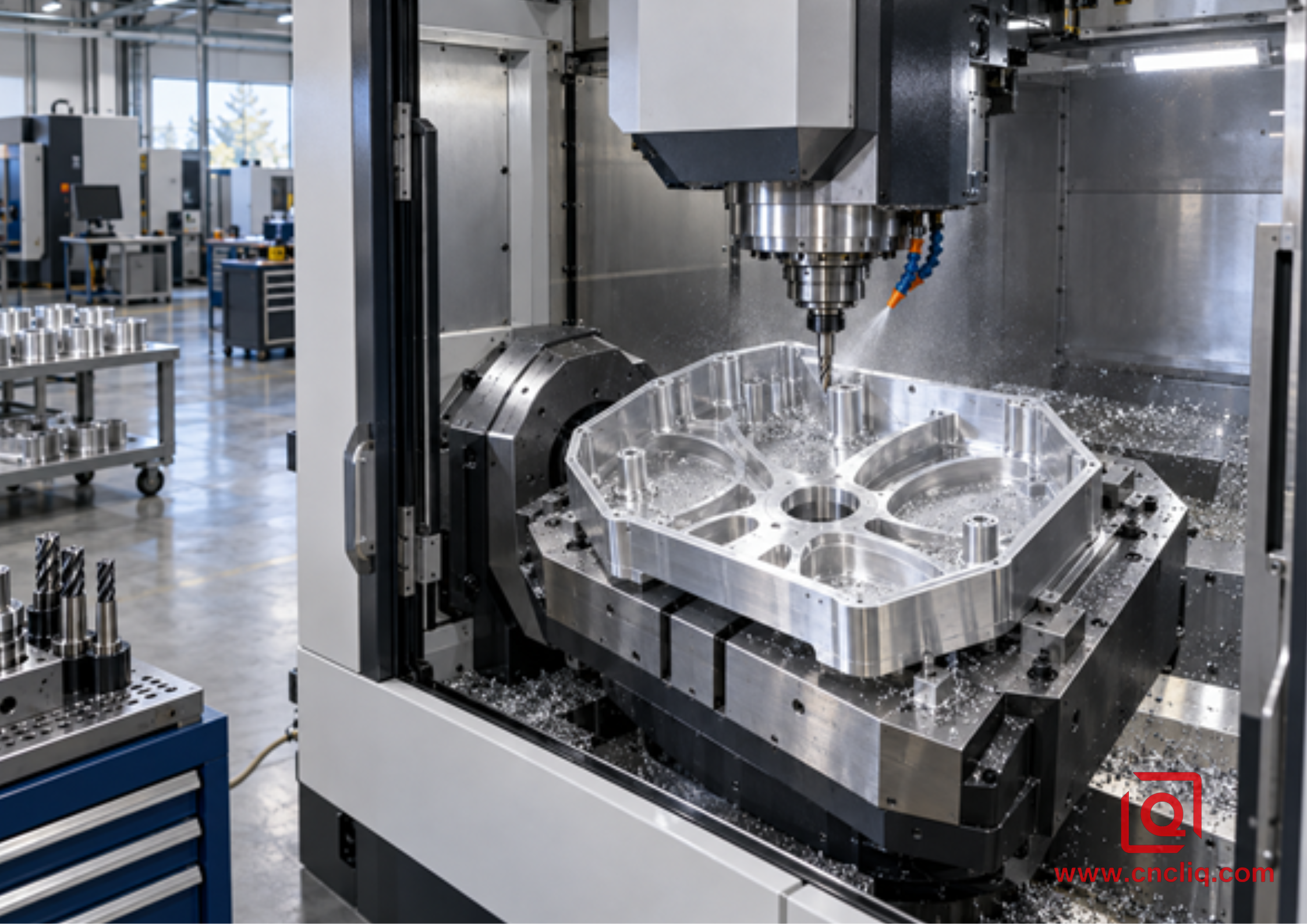
Are you still deciding between climb milling and conventional milling for a thin-walled aluminum part—and wondering why the “better” direction on one wall can ruin the next? This guide explains the choice from a shop-floor point of view. You will see how chip formation, wall support, cutter deflection, toolpath direction, and inspection timing work together. The short answer is that climb milling is usually the first choice on a rigid CNC, but thin walls do not reward blanket rules. The correct direction is the one that sends the dominant cutting force into the strongest available support while keeping engagement stable.
If you are preparing an RFQ, send the 3D model, a ballooned drawing, alloy and temper, annual volume, surface-finish requirement, coating, and the datums that matter after unclamping. Those details let a machining supplier quote a controlled process rather than simply price machine time.
The 30-Second Answer
|
Shop-floor condition |
Start with |
Why it is a sensible starting point |
What must be verified |
|
Modern CNC, rigid fixture, open side wall |
Climb milling |
Thick-to-thin chip formation reduces rubbing and normally improves chip evacuation |
The force must not pull the wall into unsupported space |
|
Tall flexible wall with support behind the cutter force |
Climb milling |
The support reacts the load and limits wall movement |
Check wall taper at top, middle, and base |
|
Long wall that bows during the climb finish |
Conventional finish test or opposite-side climb path |
Deflection direction may matter more than average cutting-force reduction |
Compare both directions on a coupon or first article |
|
Manual or worn machine with measurable backlash |
Conventional milling |
It is less likely to pull the table through drive-system clearance |
Backlash, workholding, and operator safety |
|
Full-width slot |
Neither direction is purely maintained |
Both sides of the cutter are engaged |
Use a controlled-entry or adaptive strategy and manage chips |
|
Rough, oxidized, or interrupted surface |
Case-dependent |
Gradual conventional entry can protect an edge; stable climb may still be better |
Follow the toolmaker’s application data |
The practical rule is simple: default to climb milling on a stable CNC, then earn that choice by checking support direction, radial engagement, wall response, and dimensional results. Seco Tools notes that climb milling is normally recommended because it reduces entry rubbing and moves heat into the chip, while also recognizing that conventional milling can help on rough or thin-walled work in some conditions. That nuance is the heart of this article.
What Changes Between Climb and Conventional Milling?
In climb milling, also called down milling, the cutter’s tangential motion at the contact point follows the feed direction. A tooth enters at its greatest chip thickness and leaves near zero. In conventional milling, or up milling, the tooth enters near zero chip thickness and the chip grows toward the exit.
That small geometric difference changes four things at once.
First, conventional entry includes a short rubbing stage before the edge forms a true chip. With ductile aluminum, rubbing can encourage heat, smearing, and built-up edge if the edge is dull or the programmed chip load is too low. Climb cutting begins with a more definite bite, so a sharp aluminum-specific tool usually shears more cleanly.
Second, chip flow changes. A climb path tends to leave chips behind the cutter rather than carrying them into the next tooth. Recut aluminum chips can weld to the edge and scratch a finish, so air blast or correctly directed coolant still matters even when the toolpath direction is favorable.
Third, the force vector changes. General diagrams often say climb pushes a part down and conventional lifts it. That is useful for face milling, but it is incomplete for a thin vertical wall. Side milling creates radial and tangential components whose actual direction depends on spindle rotation, contour side, entry angle, and where support exists. CAM simulation must be read together with the fixture, not as an isolated arrow.
Fourth, backlash matters. A climb cut can pull the feed system into clearance on an older machine. Modern CNC machining centers use preloaded motion systems, so this risk is normally controlled, but it should never be assumed when equipment condition is unknown.
For a concise comparison of multi-axis machine behavior and setup reduction, see Liqin’s guide to 3-axis versus 5-axis CNC machining.
Why Thin-Walled Aluminum Changes the Usual Rule
A thick block absorbs a changing force with little visible movement. A 1.5 mm wall standing 40 mm above its base behaves more like a spring. The tool moves; the wall moves; the programmed stock allowance is no longer the stock allowance the edge actually sees.
Wall stiffness falls rapidly as unsupported height increases. Cutter stiffness behaves in a similarly unforgiving way: Sandvik’s published deflection relationship is proportional to overhang cubed and inversely proportional to cutter diameter to the fourth power. In plain language, a little extra stickout can matter a great deal. Use the shortest practical assembly and the largest tool that the internal radii allow.
Aluminum also responds quickly to heat. Kaiser Aluminum lists a mean coefficient of thermal expansion of 23.6 µm/m·K for 6061 between 20 °C and 100 °C. A local 10 °C rise over a 300 mm feature corresponds to about 0.071 mm of free thermal growth. A clamped part will not expand freely or uniformly, which is exactly why finishing a hot, unevenly restrained thin wall can produce a cold inspection surprise.
The alloy temper matters too. A supplier should not treat “aluminum” as a complete material callout. 6061-T6, 6061-T651, 7075-T6, and 7075-T651 can arrive with different product-form histories and residual-stress behavior. Liqin’s 6061 vs. 7075 aluminum machining guide is a useful internal reference when strength, corrosion resistance, cost, and machinability must be balanced.
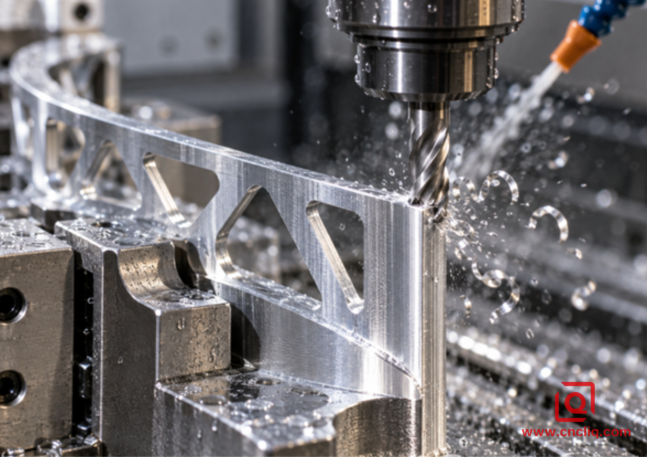
Close-up of a carbide end mill finishing a supported thin aluminum wall
A Better Decision Method: Follow the Force Into the Fixture
Before choosing a direction, mark the wall’s supported side, free side, top edge, base radius, neighboring ribs, and clamp reactions. Then ask five questions.
1. Where can the wall move?
The least-supported direction is the risky direction. If a climb pass pushes the wall toward a fitted soft jaw, sacrificial rib, wax support, or solid parent stock, it may be very stable. If the same path pulls the wall toward an open pocket, deflection may increase. Reversing the contour can be more effective than cutting the feed by 50% because it changes where the load closes.
2. Is the wall still connected to useful stock?
Do not remove all support and then ask a finishing pass to repair the result. Machine thin walls progressively while a broad section remains behind them. Alternate sides where geometry permits. Harvey Performance recommends stepped axial machining and progressively lighter radial passes as wall height grows; this preserves support longer and reduces tool pressure near the final surface.
3. Is the cutter stiff enough?
Check tool diameter, flute length, holder reach, runout, and corner radius. A long flute does not become rigid because the feed is reduced. In fact, feeding too lightly can turn cutting into rubbing. A reduced-neck tool can provide reach while keeping more shank material, but its application must match the pocket and chip-clearance needs.
4. Is radial engagement controlled?
Thin walls dislike sudden engagement changes. A constant-engagement roughing path normally produces a steadier load than a conventional pocket path that buries the cutter in corners. For finishing, leave a consistent radial allowance. Avoid a “zero-stock” toolpath that alternates between cutting and polishing due to wall movement.
5. What does inspection say after release?
An on-machine probe can confirm position while the part is still constrained. It cannot prove the part will hold the same geometry after unclamping and temperature equalization. The first article should be checked free-state at defined datums, with wall thickness, profile, perpendicularity, flatness, and taper sampled at more than one height.
Shop-Floor Workflow for Selecting the Milling Direction
Step 1: Define the functional geometry
Separate critical walls from clearance walls. A 2.00 mm nominal wall with a profile tolerance tied to datum A requires a different plan from a protective cover with generous clearance. Identify sealing faces, bearing seats, connector cutouts, cosmetic surfaces, and edges where burr direction affects assembly.
Step 2: Establish stable datums before thinning the part
Machine robust locating features early. Keep enough stock around the future wall to resist roughing loads. If multiple faces must be related tightly, a 4-axis or 5-axis setup can reduce refixturing error, but fewer setups do not remove the need for balanced material removal.
Step 3: Rough with predictable engagement
Use a sharp aluminum geometry, effective chip evacuation, and a constant-engagement path where suitable. Climb milling is the normal starting direction on a rigid CNC. Leave uniform semi-finish stock; the exact amount should be based on wall height, material condition, tool reach, and measured process capability rather than copied from a generic chart.
Step 4: Semi-finish while support remains
Work down the wall in levels or alternate sides of a rib. Do not finish one full-height side and then remove the material that was supporting the opposite side. Where the part is sensitive to residual stress, unclamp and allow it to stabilize before establishing the finishing setup.
Step 5: Run a direction trial on the first article
For a difficult wall, create two short test segments under the same spindle speed, feed per tooth, radial allowance, axial depth, coolant condition, and tool overhang. Finish one in climb and one in conventional. Measure surface roughness, taper, wall thickness, and free-state profile. This is faster than debating direction from theory while scrapping production parts.
Step 6: Finish from the stable end
Where possible, start near the wall base or a stiff rib and move toward the flexible region. Keep corner engagement smooth. Autodesk warns that forcing a cutter into an internal corner with a radius equal to the tool radius can create chatter and distort the finish; a blended toolpath or rest-machining operation prevents that engagement spike.
Step 7: Consider a controlled spring pass only when evidence supports it
A repeat path at the same offset can remove material left by elastic recovery, but a blind spring pass can rub, heat the wall, or polish only the top. If a climb finish produces measurable taper, test a light conventional correction pass with the same thermal and support conditions. Record what changed.
Step 8: Deburr without bending the feature
Thin edges are easy to roll over by hand. Define which side may carry the exit burr and choose path direction, chamfering, or edge-break tooling accordingly. Inspect the edge after anodizing or other finishing if coating buildup affects mating features.
Starting Parameters: Use a Window, Not a Promise
The values below are engineering trial windows for a sharp, aluminum-specific carbide end mill on a rigid CNC. They are not universal production settings. Confirm the cutter maker’s data, machine limits, tool length, holder balance, alloy/product form, coolant, and fixture before release.
|
Variable |
Conservative trial approach for thin walls |
Why it matters |
|
Cutter |
3-flute, polished or aluminum-specific geometry |
Provides chip space and a sharp shearing edge |
|
Tool diameter |
Largest diameter allowed by internal radii |
Stiffness rises strongly with diameter |
|
Overhang |
Shortest reach that clears the feature |
Deflection rises approximately with overhang cubed |
|
Cutting speed for 6061 |
Begin within the toolmaker’s published carbide range; validate heat and balance |
Machine, coating, coolant, and holder limits vary |
|
Feed per tooth |
Keep above the rubbing regime while limiting wall load |
Feed that is too low can smear instead of cut |
|
Roughing radial engagement |
Low and controlled with constant engagement |
Reduces force spikes and corner overload |
|
Finishing radial allowance |
Uniform, measurable, and large enough to form a chip |
An inconsistent skim pass gives inconsistent pressure |
|
Axial strategy |
Step down or alternate sides as support disappears |
Preserves wall stiffness during the operation |
|
Coolant/air |
Aim reliably at the cutting zone and evacuation path |
Prevents recutting and aluminum adhesion |
For a numerical example only, a 10 mm cutter at a cutting speed of 400 m/min calculates to about 12,732 rpm using n = 1000Vc/(πD). With 3 flutes and 0.05 mm/tooth, the programmed feed is about 1,910 mm/min using vf = n × z × fz. Those numbers are not a recommendation for every 10 mm tool. They simply show how a documented chip load connects spindle speed and feed, which is far more useful than specifying feed rate alone.
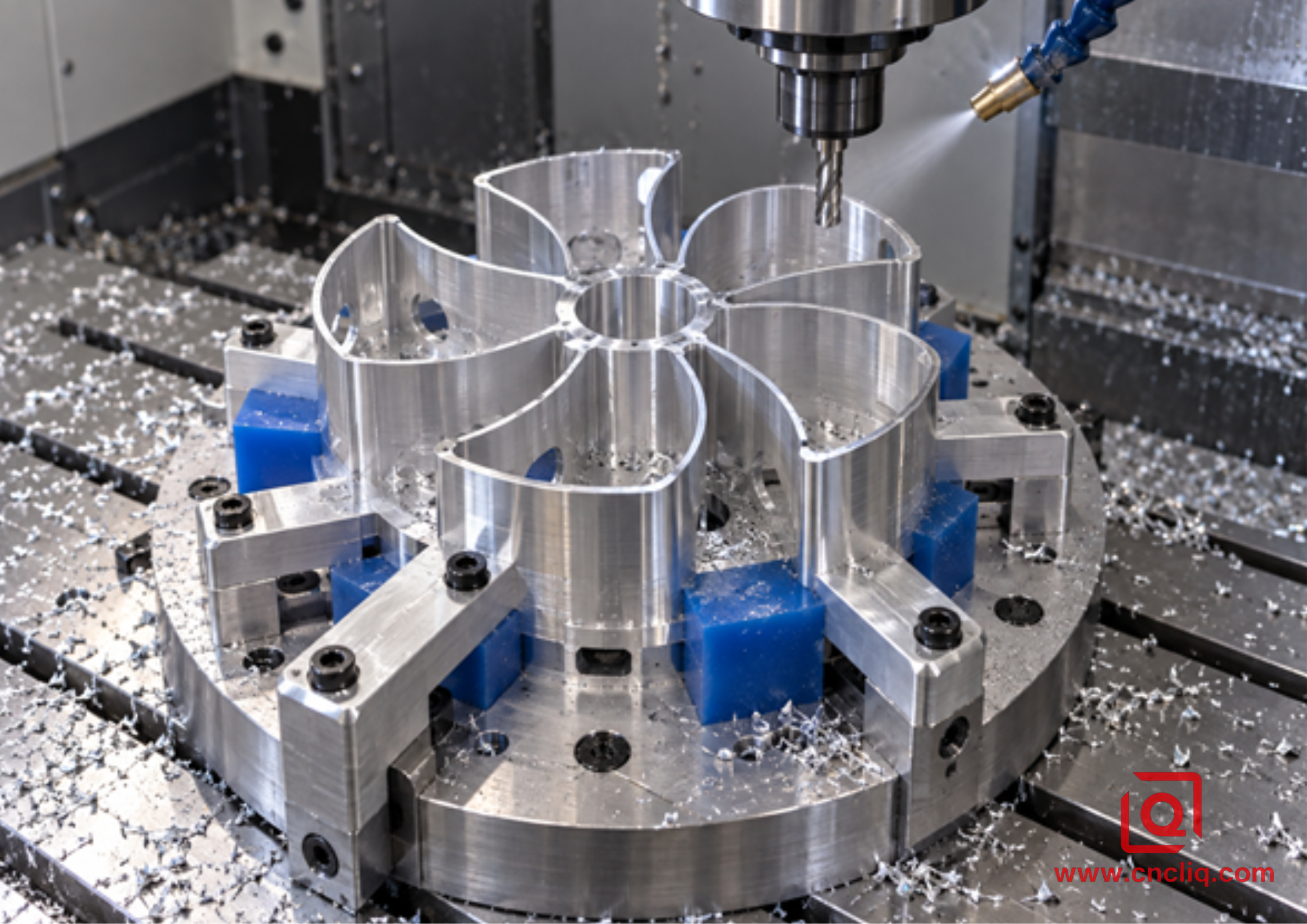
A modular fixture supporting a petal-shaped thin-walled aluminum housing
Fixturing Often Decides the Winner
Direction cannot rescue poor workholding. A vise that squeezes a thin housing into shape may produce a perfect in-cycle measurement and a distorted released part. Use broad, repeatable contact, control clamp torque or pressure, and keep cutting reactions close to locators.
Useful support methods include machined soft jaws, sacrificial tabs or bridges, removable wax or thermoplastic fill, low-melting support media selected under an approved process, vacuum fixtures with positive lateral stops, and conformal backup blocks. Each method needs a removal and cleanliness plan. Never introduce a filler near a medical, optical, or fluid-control component without confirming residue and traceability requirements.
Liqin’s existing article on preventing thin-wall deformation in aluminum CNC machining covers the broader deformation problem. For this specific decision, the fixture should be reviewed as a force map: where will the climb load go, where will the conventional load go, and which path closes the force into a locator instead of opening the wall into air?
CAM Verification: Do Not Trust the Label Alone
“Climb” in a CAM dialog is not enough. Confirm spindle direction, tool side, closed-contour direction, cutter compensation, lead-in, lead-out, and rest-machining transitions. In complex pockets, the local contact can change even when the operation carries one global direction setting. Autodesk explicitly notes that some geometry cannot maintain one direction throughout the entire path.
Watch the simulation at corners and narrow channels. Flag any move that suddenly increases engagement, drags chips across the finished surface, or reverses around an island. Review machine acceleration too: a thin wall can be excited by repeated direction changes even when average cutting force looks reasonable.
The programmer, setter, and inspector should share the same revision of the model and drawing. A practical setup sheet records tool assembly, measured runout, fixture pressure or torque, roughing and finishing allowances, coolant condition, tool-life limit, probe routine, and free-state inspection timing.
Anonymous Customer Case: Thin-Walled Aluminum Control Enclosure
An anonymized industrial automation customer requested a compact 6061-T651 control enclosure with a deep pocket, connector windows, internal bosses, and 1.6 mm nominal perimeter walls. The drawing tied the connector pattern and a gasket face to a common datum structure. The first process concept treated every contour as climb milling because the machine was a modern CNC.
The engineering review showed a problem: on one long wall, the selected climb direction sent radial force toward the open pocket while the opposite wall was still backed by parent stock. Instead of changing the entire job to conventional milling, the team changed the sequence. Roughing used a constant-engagement climb path with uniform stock. Semi-finishing alternated the 2 long sides while a sacrificial bridge remained near each connector opening. The primary finish stayed climb on the supported sides; the vulnerable wall used a reversed contour for a short finishing segment after a test cut showed lower free-state taper. A final light edge-break operation placed the burr away from the gasket face.
Inspection included wall thickness at 3 heights, profile relative to the functional datums, gasket-face flatness after release, and connector position by CMM. The case did not prove that conventional milling is globally better. It proved something more useful: a mixed-direction strategy, tied to support and measurement, can outperform a single CAM default.
For similar custom work, Liqin’s listed marine-grade aluminum explosion-proof lighting top lid illustrates the kind of machined aluminum cover geometry where sealing faces, ribs, wall stability, and surface protection must be considered together. Project-specific dimensions and results still depend on the approved drawing and quality plan.
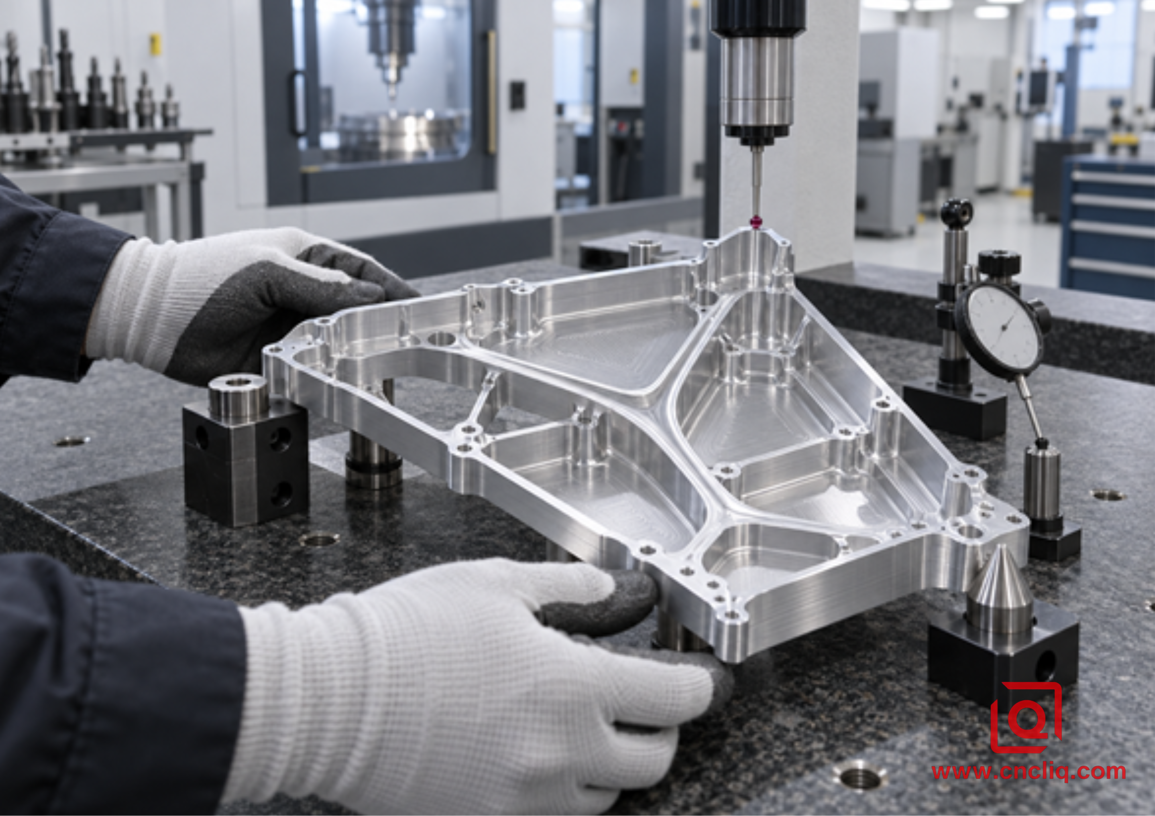
CMM inspection of a thin-walled aluminum tray after machining
Inspection and RFQ Data That Prevent Expensive Assumptions
Surface finish alone does not prove geometric accuracy. A wall may look bright yet be tapered; a CMM may report an acceptable constrained part that moves after release. Define the inspection state, temperature, datum setup, sampling plan, and coating condition. Liqin’s article on CMM inspection for custom aluminum machining explains how dimensional verification fits into a controlled OEM process.
To obtain a useful quote, include:
· 2D drawing and native or neutral 3D model;
· alloy, temper, product form, and any approved substitutes;
· critical wall thickness, profile, flatness, perpendicularity, and surface roughness;
· cosmetic zones and permitted tool marks;
· coating type and whether dimensions apply before or after coating;
· prototype quantity, batch quantity, annual demand, and target delivery;
· mating-part or assembly context for critical features;
· inspection report, material certificate, and traceability expectations.
If the wall direction, datum scheme, or tolerance stack is still uncertain, send the design before freezing the drawing. A DFM review can often add a small support radius, move a clamp land, relax a nonfunctional tolerance, or change the finishing sequence before those decisions become expensive. You can submit the package through Liqin’s contact page for a project-specific review and quotation.
FAQ
1. Is climb milling always better for thin-walled aluminum?
No. It is the normal starting point on a rigid CNC because it forms a thick-to-thin chip, reduces entry rubbing, and usually supports clean chip evacuation, but the thin wall’s support direction can override that general advantage. If the climb force moves the wall into open space while a conventional path closes it against support, a controlled conventional finish may produce better geometry. Test under equal parameters and inspect the released part.
2. Why does a thin aluminum wall measure correctly on the machine but fail after unclamping?
Clamps, vacuum, parent stock, and thermal gradients can hold the part in a temporary shape. The probe measures that constrained condition. When the fixture releases, elastic strain and residual stress redistribute, and the wall can spring or twist. Define a free-state inspection after temperature stabilization, use balanced stock removal, and avoid excessive clamping pressure.
3. Should I reduce feed whenever a wall chatters?
Not automatically. Lowering feed per tooth too far can make a sharp edge rub, increasing heat and built-up edge. First check engagement spikes, tool overhang, runout, support, chip evacuation, and whether the force points into the weak direction. Then change 1 controlled variable at a time. A shorter tool or lighter radial engagement often solves the cause more directly.
4. Can 1 toolpath stay in climb milling around an entire pocket?
CAM can request climb direction, but local engagement around islands, narrow channels, rest material, and corners may not remain equivalent. Full-width slotting engages both sides of the cutter, so it is not purely climb or conventional. Review contact in simulation, use smooth entry moves, and separate critical finishing contours when direction must be controlled.
5. What should a buyer send for an accurate thin-wall CNC quote?
Send the 3D model, fully dimensioned drawing, aluminum alloy and temper, critical datums, wall and floor thicknesses, tolerance and roughness requirements, coating, inspection documents, quantities, and delivery target. Mark which surfaces seal, locate, or remain cosmetic. That information allows the supplier to plan fixturing, machining sequence, cutting direction, inspection, and realistic process risk before pricing.
Summary
Climb milling is usually the best starting direction for thin-walled aluminum on a rigid CNC, but it is not an automatic winner. The reliable method is to map the cutting force into the fixture, preserve support during roughing and semi-finishing, use a stiff short tool with controlled engagement, verify local CAM contact, and inspect the part after release. When the evidence shows that a vulnerable wall responds better to a conventional finish or a mixed-direction strategy, follow the measurement—not the label in the CAM dialog.
Contact Information
Company: Ningbo Liqin Industry Co., Ltd.
Daily customer maintenance & after-sales support:service@shturl. zhuwanying@cncliq.com
New inquiry, quotation & order discussion:business@shturl. zhouli@chinaliqin.com
Hotline: +86 18757148656
Disclaimer
All technical articles, material specifications, machining recommendations, and surface treatment details published on this blog are for informational and reference purposes only. Please note that general blog insights do not replace signed technical agreements. Because custom parts vary by material heat numbers, machine calibrations, and specific tolerances, binding quality specs are governed solely by your approved CAD drawings, signed contracts, and formal quality plans.
All customer case studies featured on this blog have been thoroughly anonymized and sanitized. The performance metrics, manufacturing workflows, and imagery displayed serve solely to demonstrate our custom machining capabilities and do not represent a single universal standard for all orders.
Liqin Manufacturing Team
Built on 18 years of precision engineering experience, Ningbo Liqin Industry manufactures high-tolerance metal components for demanding global markets. We operate out of a 6,500 m² production hub equipped with over 150 machines, running 4-axis and 5-axis CNC machining, mill-turn machining, cold extrusion, and pressure die casting under one roof. This setup allows us to manage projects seamlessly, taking parts from initial CAD concepts directly to finalized shipments.
We handle quality control with zero compromise. We treat tight tolerances with the engineering discipline they require. Backed by ISO 9001, ISO 13485, and IATF 16949 certifications, our QA engineers run strict IPQC, FQC, and OQC checks on every single production batch. From CMM dimensional mapping and optical profiling to hardness and salt-spray testing, we validate your critical specs upfront—so you receive drop-in ready components with zero assembly headaches or costly line stoppages. On top of manufacturing, you can rely on us for two-hour response times on new RFQs, direct support for prototype sampling, and smooth export shipping across Europe, North America, Asia, and Oceania.
Welcome your inquiries and samples. Visit our website or contact us directly for a competitive quote!
