 English




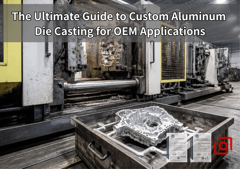
Step into an active high-pressure die casting foundry during volume production. Ten seconds tell you if a cell hums along or drifts into an expensive breakdown.
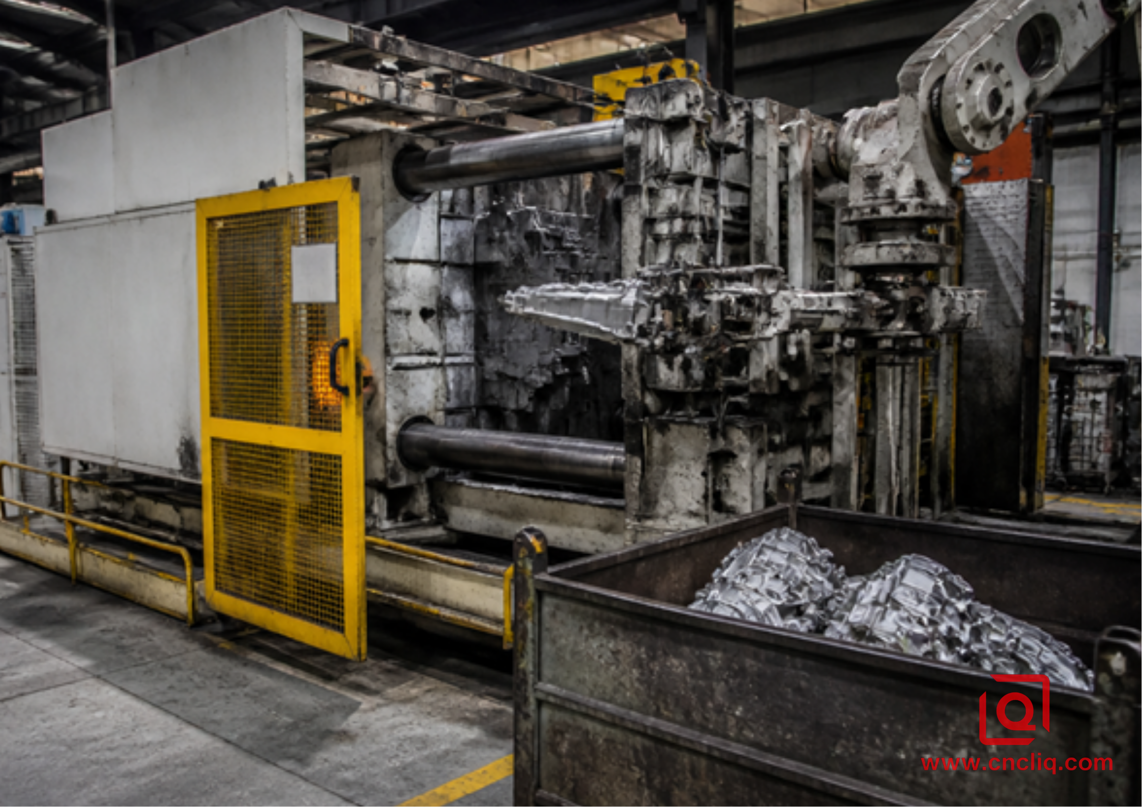
The machine's cadence says it all.
Listen for the hydraulic shot piston ramming home, ejector pins snapping cast blanks off the parting plane, and lube manifolds blasting coolant across glowing H13 die blocks. If you buy custom aluminum enclosures, motor carriers, or chassis structures under tight OEM delivery dates, that pace dictates success or scrap. It is what keeps downstream CNC fixtures loaded instead of dumping thousands of dollars into the scrap pile over hidden porosity.
HPDC turns raw ingots into stiff, thin-wall, intricate parts in cycles under 45 seconds. Still, scaling a neat 3D model up to 50,000 flawless castings takes real work. You have to dial in runner velocity, balance die temperatures, nail the second-phase shot switch, and account for thermal shrink as the metal freezes.
Tooling leads, foundry techs, and OEM buyers handle aluminum programs with these practical controls to hold scrap down, lock cycle times in place, and keep part costs right where they belong.
1. The Production Math: Billet CNC vs. High-Pressure Casting
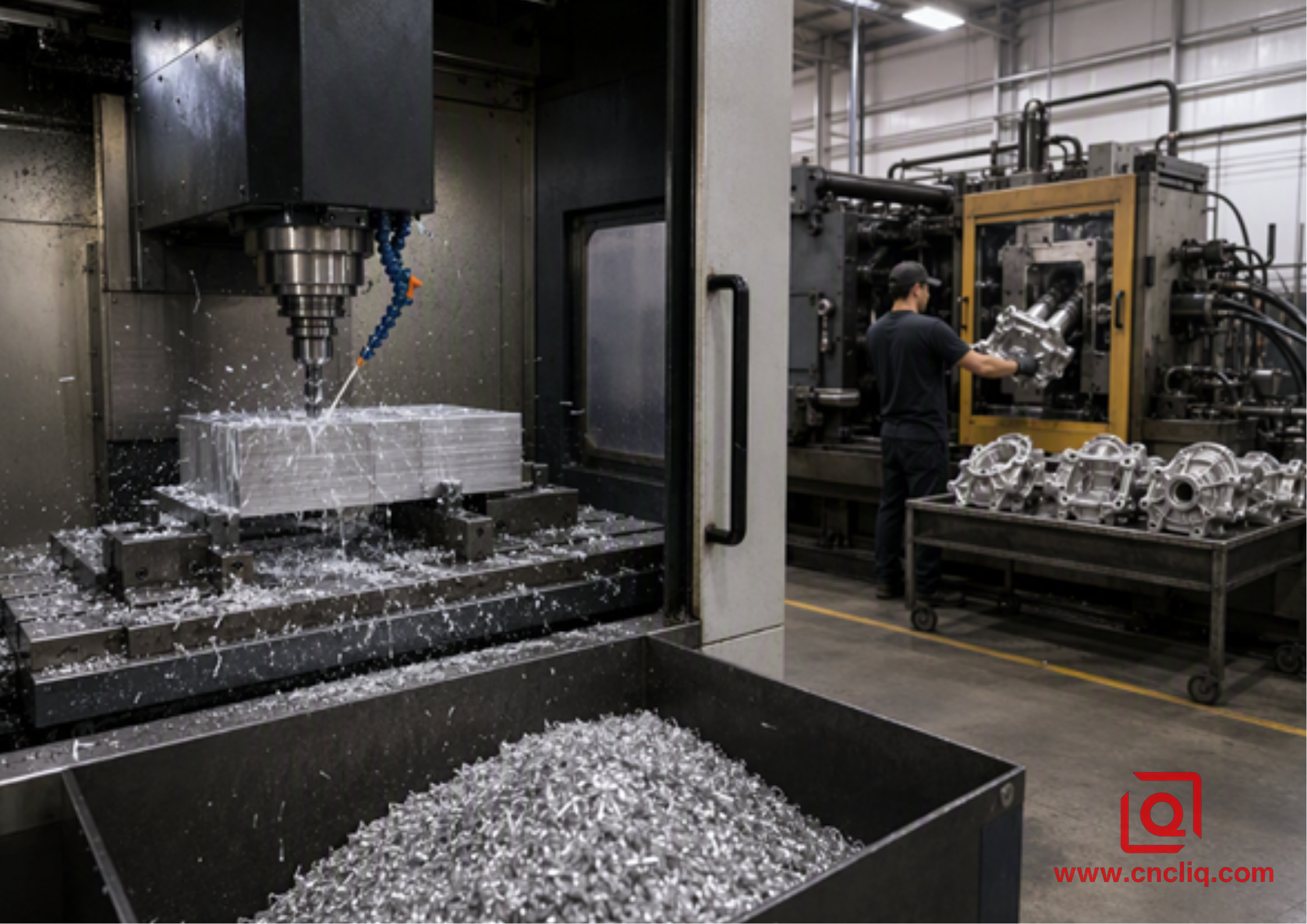
Every manufacturing path carries an economic break-even point. When designing a new aluminum component, the first fork in the road is deciding whether to machine the part directly from extruded 6061-T6 plate or cut a dedicated steel die casting tool.
If your program demands fewer than 1,000 parts per year, do not buy a casting tool. Multi-axis CNC milling from billet stock wins on upfront cash flow every single time. You dodge upfront tooling checks, letting designers tweak hole centers, wall steps, and pocket floors right in the CAD file—no waiting weeks for toolmakers to weld up, re-mill, or spark-erode hardened inserts.
Past the 3,000 to 5,000-part-a-year mark, though, chewing through solid billet turns into pure money down the drain.
[ CNC Billet Machining: Solid Block ]  --->  [ 80% Chips / Scrap Bin ] + [ 20% Net Part ]
[ High-Pressure Casting: Molten Ingot ] --->  [ 95% Net Shape Part ]   + [ 5% Remeltable Gates ]
Hogging a deep enclosure from solid billet means paying upfront for bulk aluminum, burning 30 to 45 minutes of spindle run-time just to shred 80% of that paid stock into scrap chips, and chewing through pricey end mills.
High-pressure die casting flips that math completely:
-
Rapid Injection: The casting press injects liquid alloy into hardened tool cavities under intense hydraulic pressures (ranging between 30 and 100 MPa).
-
Extreme Gate Velocity: The metal shoots through narrow in-gates at speeds between 40 and 60 meters per second, atomizing into a fine fluid front that sweeps through intricate cooling fins and deep structural ribs in twenty to forty milliseconds.
-
Instant Solidification: Liquid alloy freezes tight against water-chilled cavity steel in under a second.
-
Near-Net Geometry: Castings leave the trim press ready to mount. Bosses, gussets, cooling blades, connector ports, and weight-relief pockets are already formed.
Downstream CNC work drops from heavy hogging down to brief, high-speed cleanup passes on critical O-ring faces, bearing bores, and precision dowel locations.
2. Alloy Selection: Chemistry and Fluidity Matter More Than Raw Strength
Design engineers often mess up by picking a casting alloy straight off a generic spec sheet based purely on listed tensile numbers. In HPDC, on-paper strength is worthless if the melt freezes in the runner before packing out the far corners of the tool.
Liquid aluminum behavior during cavity fill determines whether your thin heat-sink fins pack out cleanly or leave cold shuts and knit lines.
[ Silicon Content (Si %) ]  --->  Governs fluidity and thin-wall mold fill speed
[ Copper Content (Cu %) ]   --->  Sharpens machinability and hardness; reduces corrosion resistance
[ Iron Content (Fe %) ]     --->  Prevents molten alloy from soldering / sticking to tool steel
[ Magnesium Content (Mg %) ] --->  Enables precipitation hardening and structural yield strength
-
A380 (ANSI/AA Standard): The undisputed global workhorse for industrial gearboxes, pump bodies, and electronics cases. With roughly 8.5% silicon, it flows reliably through the runner, while about 3.5% copper makes it easy to machine, hardens the matrix, and keeps tapped threads crisp. The catch is corrosion. Leave raw A380 in salt spray or marine air, and it pits fast unless you lay down a conversion coat or powder primer.
-
ADC12 (JIS H 5301 Standard): The standard across Asian casting facilities, functioning as the functional twin to A380. With silicon bumped up to between 9.6% and 12.0%, ADC12 flows like water. It fills paper-thin walls down to 1.2 mm and navigates complex cooling fin matrices while minimizing the risk of die soldering.
-
A360: Built for nasty working environments and heavy abuse. Holding copper under 0.6% alongside roughly 9.5% silicon gives this alloy great rust protection and higher elongation when hit with shock loads. That said, it is a pain to run compared to A380. The freezing range is much narrower, forcing you to clamp down hard on die steel temperatures.
-
AlSi10Mg (DIN EN 1706): The top choice for automotive powertrain mounts, electric vehicle inverter housings, and high-output LED fixtures. It combines high thermal conductivity (roughly 130 W/m·K) with low hot-cracking tendencies during solidification.
3. Engineering Trade-Off Matrix
Choosing between manufacturing routes and alloy families requires balancing tooling capital, part geometry, thermal demands, and secondary processing overhead:
| Operational Parameter | High-Pressure Die Casting (HPDC) | CNC Billet Machining (6061-T6) | A380 / ADC12 General Purpose Alloy | A360 / AlSi10Mg Specialized Alloy |
| Target Production Volume | Best for > 3,000 parts per year | Best for < 1,000 parts per year | Massive runs; general OEM hardware | High-duty thermal & outdoor units |
| Material Utilization Rate | ~92% to 95% (runners remelted) | ~15% to 35% (heavy chip waste) | Readily available standard melt | Tighter ingot purity controls needed |
| Minimum Wall Thickness | 1.2 mm to 2.0 mm (readily cast) | 0.8 mm (slow, high chatter risk) | Excellent for ultra-thin fins | Good for balanced structural walls |
| Thermal Conductivity | 92 to 96 W/m·K | 150 to 170 W/m·K | Adequate for standard heat spread | 115 to 130 W/m·K (superior dissipation) |
| Native Corrosion Resistance | Requires passivate / coating | High native atmospheric resistance | Moderate (needs e-coat or paint) | High (low copper content) |
| Tooling Upfront Capital | High investment (H13 steel die) | Zero dedicated mold tooling | Standard H13 / 1.2344 steel cores | Premium ESR tool steels recommended |
| Secondary Machining Speed | Rapid (0.5 mm skim cuts) | Extended (full roughing routines) | Brittle chips; fast, clean tapping | Slightly gummy; needs sharp tools |
4. Practical DFM Rules: Keeping Scrap Below 1.5%
Every casting supplier talks about Design for Manufacturability, yet tooling engineers still spend hours correcting problematic CAD models every week. A few bad modeling habits in your 3D design can lead to stuck parts, broken ejector pins, and soaring defect rates on the shop floor.
POOR DESIGN: Stepped Wall & Sharp Core        OPTIMIZED DFM: Uniform Wall & Radiused Blend
           |                                                   |
 [ Thick Section = Shrink Hole ]                     [ Constant 2.2 mm Nominal Wall ]
 [ Sharp 90° Corner = Crack Starter ]                [ Generous 1.5 mm Internal Radius ]
 [ Straight Face = Die Galling & Sticking ]          [ 2.0° Draft = Clean Ejection ]
A. Maintain Uniform Wall Thickness and Eliminate Hidden Hot Spots
The most common mistake on 3D drawings is abruptly stepping wall thicknesses—for instance, running a heavy 6.0 mm mounting boss straight into a 1.8 mm exterior wall.
When molten aluminum fills the mold, thin regions freeze in milliseconds. The chunky boss stays liquid far longer. Because the thin walls solidify first, they choke off the flow of pressurized feeding metal from the gating system. As that isolated pocket of liquid cools, it shrinks by roughly 3.5% to 4.0% in volume.
The physical result? An internal shrinkage void forms right in the center of the boss.
When your machine shop later drills and taps an M6 thread into that location, the tap breaks through into a spongy hole, stripping threads or causing leaks. Always core out the backside of heavy bosses to maintain uniform wall thickness, and apply a 3:1 gradual taper wherever thickness transitions cannot be avoided.
B. Draft Angles: Give the Mold Room to Breathe
Liquid aluminum grips steel tooling with immense force as it cools and shrinks. Without sufficient draft angle, parts will gall, drag metal off the cavity walls, or get punched through by the ejector pins.
-
External Walls: Apply a minimum of 1.0° to 1.5° draft.
-
Internal Shut-Off Cores: Provide 2.0° to 3.0° wherever component tolerances allow.
-
Deep Stiffener Ribs: Include at least 1.0° per side to prevent drag marks during ejection.
C. Radius Every Edge
Sharp internal roots trap heat and build stress in your inserts. Even worse, they fracture the incoming melt front, breaking steady flow into turbulent mist that seals in gas voids. Call out a 1.0 mm to 1.5 mm blend along every inner intersection. That simple tweak on your print regularly doubles tool life, driving cycles from 60,000 shots past 120,000 shots before any thermal check marks bite into the steel.
5. Porosity Control: Where Pressure-Tight Castings Are Won or Lost
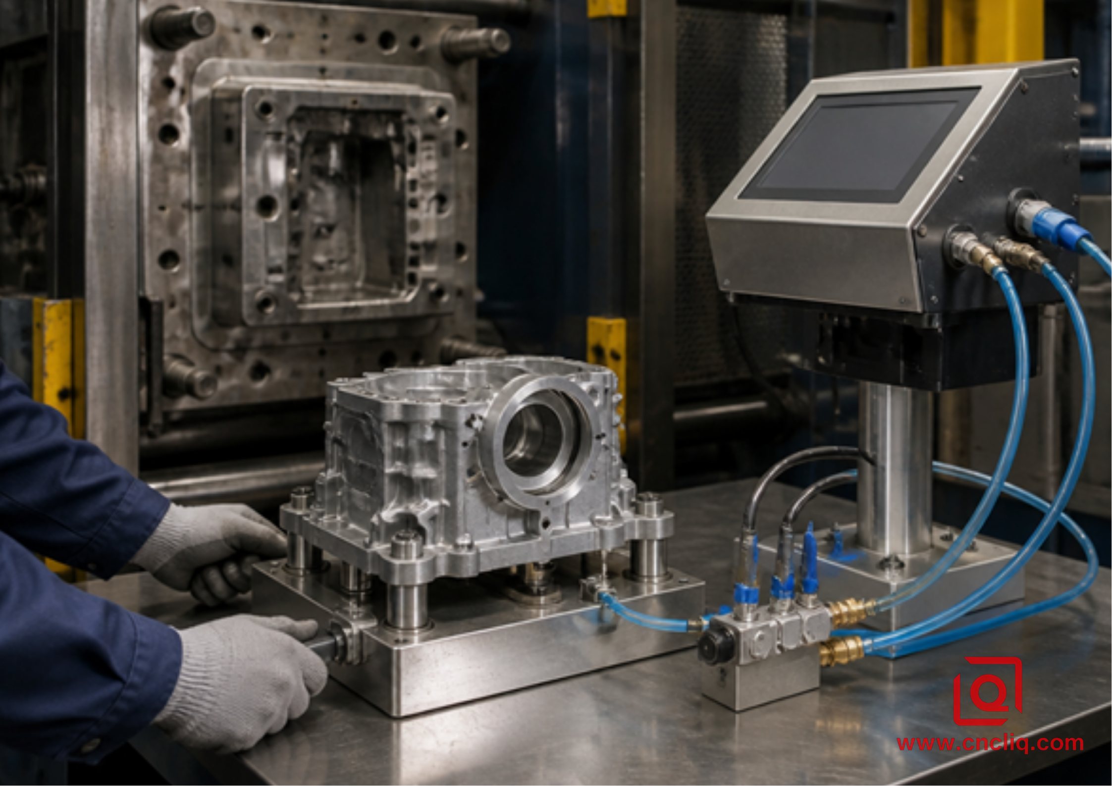
Porosity is the oldest adversary in die casting. When an OEM part requires an IP67 or IP68 hermetic seal, or contains an internal fluid channel, exposing a 0.5 mm bubble under the machined surface will scrap the entire assembly during leak testing.
Porosity comes in two distinct types:
-
Shrinkage Porosity: Jagged, spongy voids caused by volumetric contraction in isolated thick cross-sections during solidification.
-
Gas Porosity: Smooth, spherical micro-voids caused by air, steam, or burnt die lube getting whipped into the liquid aluminum during high-velocity shot injection.
Standard Shot Sleeve Venting                     Active High-Vacuum Die Casting
[ Atmospheric air trapped in cavity ]    --->    [ Die cavity evacuated to < 50 mbar ]
                |                                                |
[ High turbulence emulsifies air bubbles ] --->   [ Clean, continuous liquid alloy front ]
                |                                                |
[ Subsurface porosity exposed by CNC ]   --->    [ Dense, leak-free machined surfaces ]
To eliminate gas porosity, quality foundries deploy active vacuum-assisted casting. Vacuum valves open and pull cavity air pressures down below 50 mbar right before the shot piston ramps to high speed. The alloy enters an evacuated cavity, virtually eliminating air entrapment.
To knock out shrinkage voids in heavy wall sections, current dies rely on localized hydraulic squeeze pins. About 1 to 2 seconds after the cavity packs out—right as the melt hits its mushy, semi-solid state—a rigid cylinder punches a hardened steel pin straight into the thermal mass at 80 MPa. That punch forces the collapsing void shut from within, leaving behind a dense, solid core.
6. Real-World Case Study: Rugged Industrial Telemetry Housing
An industrial controls manufacturer came to us with an IP68-rated outdoor telemetry housing.
-
The Problem: They had been hogging the part out of a 4.5 kg solid 6061-T6 billet on a 3-axis CNC mill at a unit price of $132.00 USD. When their annual volume jumped from 600 to 14,000 assemblies, their component budget collapsed under the cost. The housing needed to shed 30 Watts of heat from internal RF modules while passing a 48-hour submersion test under 1.5 meters of water.
-
The Tooling Strategy: We engineered a single-cavity mold using premium 1.2344 ESR hot-work tool steel (hardened to 46–48 HRC). The tool integrated vacuum chill blocks and multichannel conformal cooling circuits to hold the die surface at a steady 200°C to 220°C across fast cycles.
-
DFM Changes: We cored out the four thick corner mounting posts from the underside, added 2.5° of draft, and blended all internal wall transitions into a continuous 2.2 mm nominal wall thickness.
-
Post-Machining & Coating: We cast the outer O-ring channel leaving just 0.4 mm of stock, then dialed in a quick CNC finishing cut to true up the sealing surface. From there, the box went through a zirconium prep bath followed by an architectural-grade matte black powder coat.
-
The Outcome: Every cast ADC12 housing cleared helium mass spec leak detection on the first try—hitting a 100% first-pass rate. Piece-part costs dropped hard from $132.00 down to $19.40 USD with mold amortization included, putting more than $1.5 million back in the OEM’s pocket across Year 1.
7. Practical Sourcing Checklist for OEM Buyers
Before issuing a tooling deposit or freezing production prints, run your project through these five practical validation steps:
-
Verify Tool Steel Quality and Shot Guarantees: Do not accept generic "alloy steel" descriptions. Demand certified hot-work tool steels (such as Premium Grade H13, Dievar, or 1.2344 ESR) with an explicit warranty covering 80,000 to 100,000 shots.
-
Hold Tight Machining Stock: Hold clean-up stock between 0.5 mm and 0.8 mm on primary sealing faces. Hogging off excess metal peels away the tough, chilled exterior shell, plunging right into softer base alloy peppered with gas pockets.
-
Define Sensible Radiography Limits: Work off ASTM E505 reference plates. Lock down tighter porosity thresholds along gasket tracks and tapped blind holes, bypassing unrealistic zero-void demands on purely visual surfaces.
-
Source All Operations In-House: Team up with a shop running tool builds, shot production, robotic de-flashing, CNC finishes, pressure testing, and final paint under one roof. With one team responsible from melt to shipping crate, engineering discrepancies get corrected immediately without vendor friction.
FAQs
Q1: Can aluminum die castings get anodized for looks or wear protection?
Workhorse casting alloys like A380 or ADC12 pack plenty of silicon (around 8% to 12%). Drop them into an acid tank, and that chemistry turns hostile fast—smearing the finish with a blotchy, dull gray mess. If your print insists on rich decorative colors, switch the feedstock over to low-silicon, ductile AlMg blends. Otherwise, run abrasive grit blasting underneath an e-coat or powder line for clean, durable protection.
Q2: What is the realistic lead time on tooling and first-off sample parts?
Cutting a production-ready hardened tool (like H13 or 1.2344 ESR) normally takes 30 to 45 calendar days. Total turnaround hinges directly on cavity counts and the complexity of your side-actions. Once the tool is assembled and mounted onto the casting machine, running the first T1 shot samples, trimming the gates, completing initial CNC machining, and generating a full CMM inspection report usually takes another 5 to 7 business days.
Q3: How do we prevent tapped threads from stripping or pulling out in aluminum die castings?
Cast aluminum does not match the hardness of billet stock like 7075-T6. Push hard on short thread engagements under heavy torque, and you will strip the threads right out of the hole. To lock in joint strength, hold thread engagement to at least 1.5 to 2.0 times the nominal fastener diameter. Always cast in cored holes with clean draft instead of drilling blind into spongy hot spots, or spec stainless inserts (like Helicoil or Keysert) straight into heavily loaded mounts.
Q4: What as-cast dimensional tolerances can we realistically hold without CNC machining?
Directly off the trim press, high-pressure die casting generally follows standard NADCA guidelines, reliably holding around ±0.20 mm on features under 100 mm and adding roughly ±0.002 mm per linear millimeter across larger dimensions. Any tight feature tighter than that—such as bearing bores (±0.015 mm), precision dowel pin centers, or flat O-ring sealing grooves—must be cast with 0.5 mm stock and finish-machined on a CNC mill.
Q5: What sets cold-chamber and hot-chamber casting apart for aluminum?
Aluminum runs strictly on cold-chamber equipment. At typical casting temperatures, molten alloy attacks and welds straight to ferrous components—eating away an internal submerged injection pump in short order. In cold-chamber casting, the melting furnace sits separate from the machine, and an automated ladle pours exact molten alloy doses into a horizontal shot sleeve right before each hydraulic injection stroke.
Summary
Transitioning custom aluminum designs from pilot builds to full production takes straight engineering logic. Keep annual volumes under 1,000 units, and milling straight from billet protects your working capital. Once runs cross 3,000 to 5,000 pieces, high-pressure die casting is the real move—slashing piece-part pricing while driving output skyward. Locking down minimal scrap rates comes down to clear rules: spec materials for actual field environments over spec-sheet yield ratings, core out heavy lugs to eliminate thermal pockets, add generous draft to keep tooling intact, and deploy vacuum blocks or squeeze pins to choke out subsurface voids across sealing faces. Running mold construction, casting, finish CNC, and paint through a single supplier eliminates vendor blame games entirely, locking in rock-solid components right from batch 1.
Contact Information
Disclaimer
All technical articles, material specifications, machining recommendations, and surface treatment details published on this blog are for informational and reference purposes only. Please note that general blog insights do not replace signed technical agreements. Because custom parts vary by material heat numbers, machine calibrations, and specific tolerances, binding quality specs are governed solely by your approved CAD drawings, signed contracts, and formal quality plans.
All customer case studies featured on this blog have been thoroughly anonymized and sanitized. The performance metrics, manufacturing workflows, and imagery displayed serve solely to demonstrate our custom machining capabilities and do not represent a single universal standard for all orders.
Liqin Manufacturing Team
Built on 18 years of precision engineering experience, Ningbo Liqin Industry manufactures high-tolerance metal components for demanding global markets. We operate out of a 6,500 m² production hub equipped with over 150 machines, running 4-axis and 5-axis CNC machining, mill-turn machining, cold extrusion, and pressure die casting under one roof. This setup allows us to manage projects seamlessly, taking parts from initial CAD concepts directly to finalized shipments.
We handle quality control with zero compromise. We treat tight tolerances with the engineering discipline they require. Backed by ISO 9001, ISO 13485, and IATF 16949 certifications, our QA engineers run strict IPQC, FQC, and OQC checks on every single production batch. From CMM dimensional mapping and optical profiling to hardness and salt-spray testing, we validate your critical specs upfront—so you receive drop-in ready components with zero assembly headaches or costly line stoppages. On top of manufacturing, you can rely on us for two-hour response times on new RFQs, direct support for prototype sampling, and smooth export shipping across Europe, North America, Asia, and Oceania.
Welcome your inquiries and samples. Visit our website or contact us directly for a competitive quote!
