 English




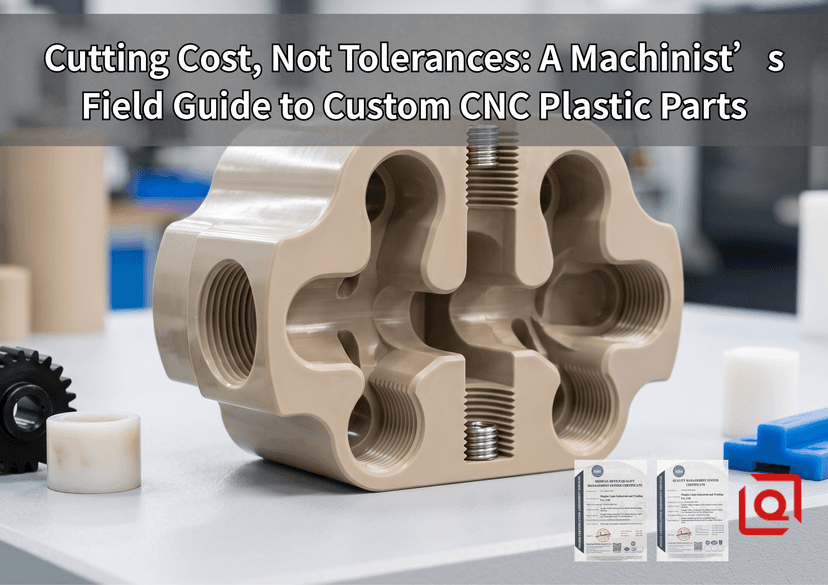
So, your engineering team just slapped a run of ultra-high-molecular-weight polyolefins or semi-crystalline thermoplastics onto our shop floor. They expect tight position tolerances, slick surface finishes, and zero stress-induced warping—all on a shoestring budget. We see it every day. Machining engineering plastics isn’t just "soft-metal cutting." If you feed PEEK like 6061-T6 aluminum, you’ll end up with gummy tool build-up, heat-sink stress cracks, and dimensions creeping out of spec before the part even hits the inspection bench.
Here’s how we dial in speed, feed, cutter geometry, and material behavior to hit sub-mil accuracy without melting your bill of materials.
1. Material Reality Check: Thermal Physics Doesn't Care About Your CAD Model
You can't brute-force plastics. Take Unfilled PEEK (Polyetheretherketone) versus Acetal Homopolymer (Delrin 150). PEEK’s coefficient of thermal expansion (CTE) sits around 47 × 10-6/ K, whereas Delrin expands at nearly 110 ×10-6/ K—almost five times that of standard alloy steels. If your machinist blasts through a heavy roughing pass with an uncooled solid-carbide end mill, the localized friction heat spikes the billet temperature by 40°C. Delrin expands during cut, you hit your finish dimension on the machine, and three hours later, as the component settles back to 20°C ambient room temp, your inner diameter shrinks right past the lower limits of ISO 2768-m.
| Material Grade | Tensile Modulus (GPa) | CTE (10-6/K) | Glass Transition Temp (Tg) | Optimal Coolant Strategy | Max Unsupported Wall (mm) |
| PEEK (Victrex 450G) | 3.8 | 47 | 143°C | Flood Water-Soluble / Compressed Air | 0.8 |
| POM-H (Delrin 150) | 3.1 | 110 | -60°C | Compressed Air / MQL | 1.2 |
| PTFE (Teflon) | 0.5 | 135 | 115°C | Cryogenic Cold Air Jet | 2.5 |
| UHMW-PE | 0.7 | 200 | -120°C | High-Pressure Soluble Oil | 3.0 |
Pro-tip from the floor: Watch out for hygroscopic resins like Nylon 6/6 (PA66). Leaving an extruded PA66 stock block unsealed on a humid shop floor for just 6 hours spikes moisture absorption from 0.2% up to 1.1% by weight. When the single-flute cutter hits that damp spot, the localized steam generation causes micro-foaming, leaving a hazy, pitted wall finish instead of an SPI-A2 polish.
2. Cutter Geometry and Machine Setup: Sharp Kills Friction
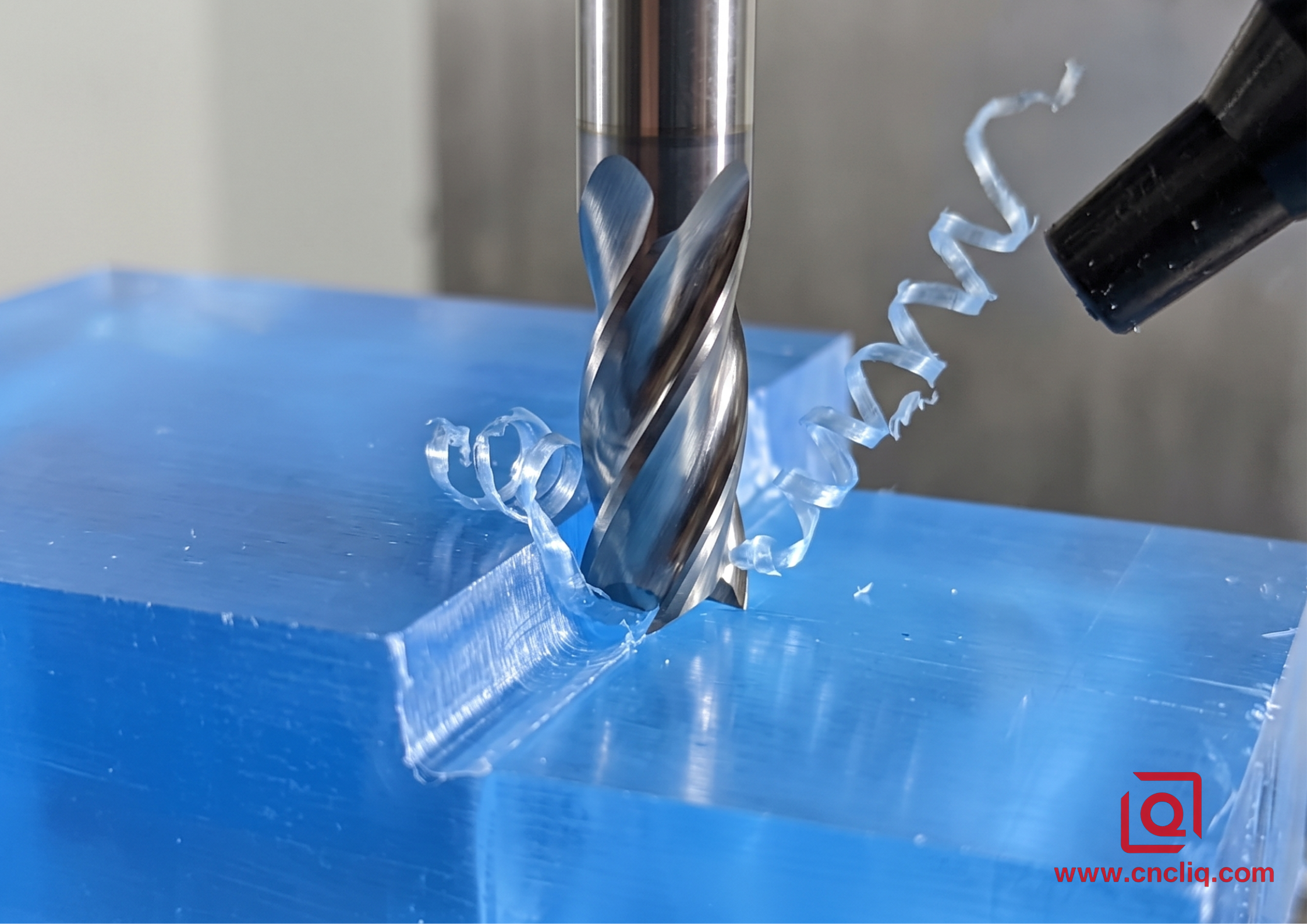
Forget standard 4-flute grain cutters designed for mild steel. To shear long-chain polymer structures without smearing:
-
Use Single-Flute or Two-Flute Upcut O-Flutes. High rake angles (15℃ to 20℃) and primary clearance angles around 12° are mandatory.
-
Polished Flutes Are Non-Negotiable. Uncoated, mirror-polished solid carbide prevents plastic chips from welding to the rake face under chip load.
-
Climb Milling Only. Conventional milling drags the cutter against the workpiece, rubbing and generating friction heat before the edge bites into the stock.
When chucking extruded bar stock, keep clamping pressures under 2.5 MPa. Standard 3-jaw hydraulic chucks tuned for steel tubing will crush thin-walled POM bushings out of roundness before the spindle even turns. Use soft aluminum jaws bored to 100% contact area, or switch to collet chucks.
3. Tool Paths, Speeds, and Feed Rates: The Heat-Dissipation Dance
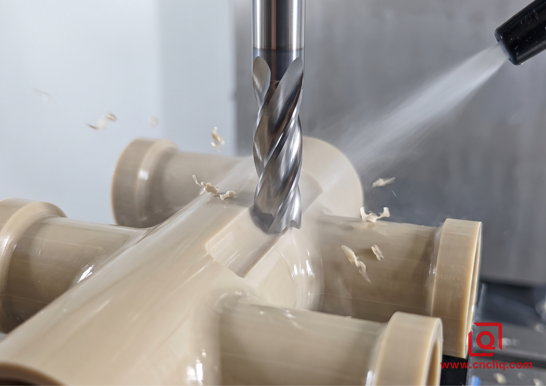
Plastics have terrible thermal conductivity. Steel conducts heat at ~50 W/m·K; PEEK sits down around 0.25 W/m·K. That means 90% of the friction heat generated at the cutting edge stays right inside the chip and the workpiece surface.
If your chip load is too thin (say, under 0.05 mm/tooth), the cutter rubs, melts the kerf, and gums up the tool flutes. If chip load is too thick, cutter pressure deflects the flexible material, causing severe chatter and dimensional tapers.
Run a 12mm 2-flute carbide end mill in POM-C at 12,000 RPM. Maintain a linear feed of 3,600 mm/min. Keep the radial depth of cut (ae) at 40% of tool diameter and axial depth (ap) under 1.5D. Blast compressed air mixed with a light vegetable-based minimum quantity lubrication (MQL) directly at the shear zone to clear chips instantaneously. Never let chips re-cut. Re-cutting plastic chips equals instant melting and cutter snap.
4. DFM Rules to Slash Machining Cycles by 40%
Want lower quotes? Fix your CAD before sending it over.
-
Increase Internal Corner Radii. Don't spec a square internal pocket corner (R = 0) or even an R3.0mm on an 18mm deep cavity. That forces us to drop down to a 2mm pencil end mill with massive overhang, leading to chatter and slow tool passes. Rule of thumb: Make internal corner radius R ≥1.1 × tool radius.
-
Standardize Thread Specs. Tapping plastics like PTFE or UHMW-PE requires oversized taps (e.g., 6H Oversize or STI thread taps). Plastic rebounds slightly after the tap retracts. If you specify deep, non-standard metric fine threads, we have to thread-mill them on a 5-axis setup. Stick to standard coarse threads (M4 × 0.7, M6 × 1.0) with engagement length limited to 1.5 × D.
-
Roughing, Annealing, Finishing Sandwich. For high-precision PEEK manifolds requiring ± 0.015mm tolerances across 200mm:
-
Step A: Rough machine leaving +0.8mm stock on all surfaces.
-
Step B: Bake in an air-circulating oven at 150℃ for 4 hours, cool slowly at 10℃/hour back to room temp to relieve internal extrusion stresses.
-
Step C: Final precision finish pass using PCD (Polycrystalline Diamond) tipped tooling.
-
5. Inspection Protocols: Measuring Soft Materials Without Distortion
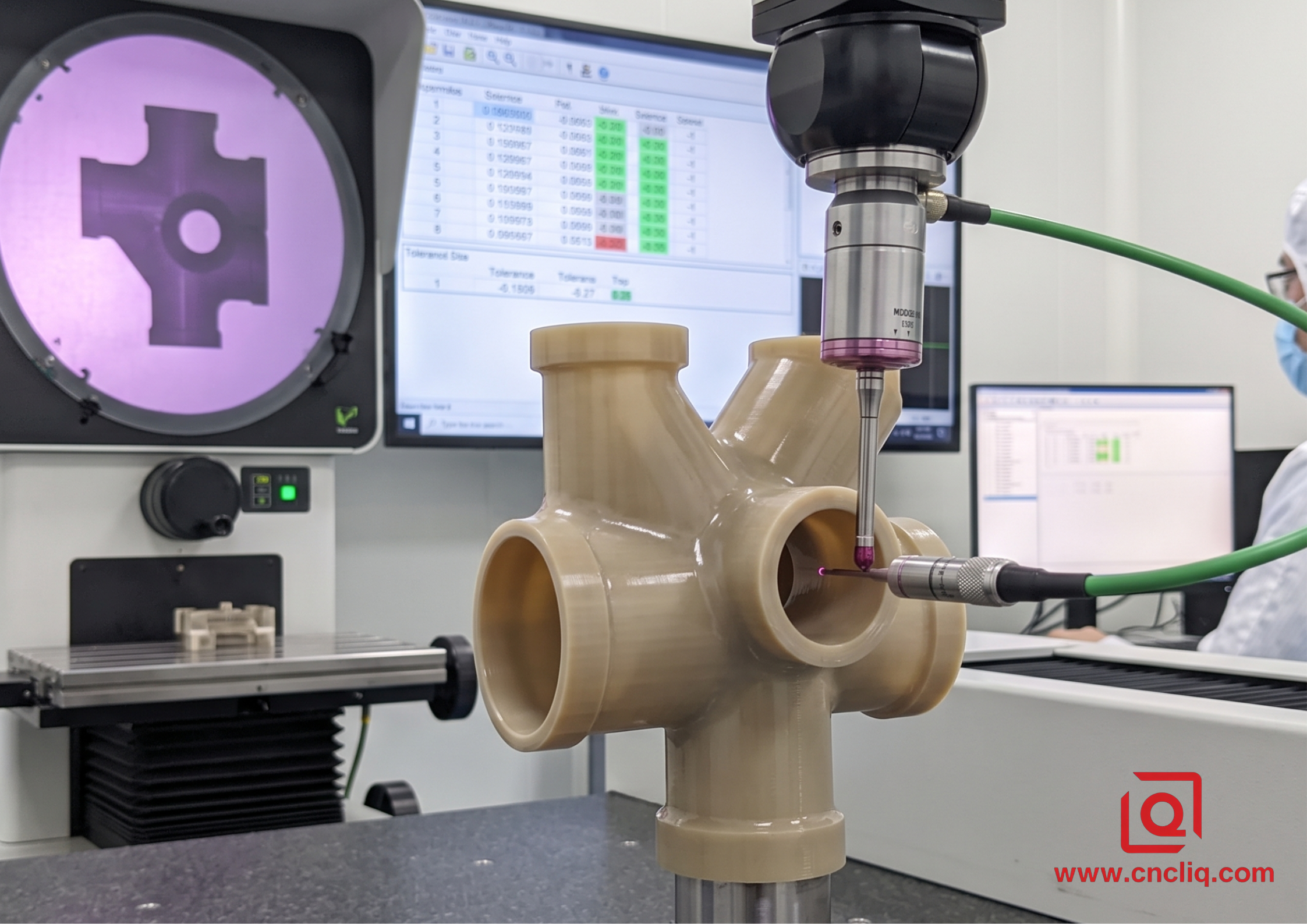
You can't measure a 70-Shore-D polyurethane sealing ring with standard vernier calipers—the jaw pressure alone deflects the part by 0.1mm, giving you a false reject.
Always mandate non-contact optical comparators or CMMs equipped with low-force touch probes (≤ 0.05N). Allow parts to stabilize in an ISO 1-compliant climate-controlled inspection room (20℃±1℃, relative humidity <50%) for a minimum of 24 hours post-machining before taking final inspection points.
By respecting thermal expansion, matching cutter geometry, and specifying smart stress-relief protocols, you strip away unneeded machining hours, eliminate scrap, and land precision plastic components that fit right the first time.
FAQs
Q1: Why do precision plastic parts warp after sitting on the shelf for a few days?
A: It’s all about residual stress release and the material's "memory." Unlike hot-rolled metal billets, extruded or injection-molded plastic stock enters our shop packed with internal locked-in tension created during its rapid factory cooling process. When we carve into that raw slab to drop a deep pocket or shave down a thin floor, we alter the internal force equilibrium. The material responds by physically relaxing—slowly warping, bowing, or twisting over 48 to 72 hours as room temperatures fluctuate.
To stop this shape-shifting, you can't just slap a raw billet onto the machine bed. For tight-tolerance work, we run a Rough-Anneal-Finish cycle. We rough-machine the profile leaving about 1.0mm of sacrificial skin, bake the semi-finished part in a temperature-controlled air-circulating oven near its heat deflection point to melt away those locked-in stresses, let it cool down gradually over several hours, and only then return it to the VMC for the final light finish pass.
Q2: Can we use standard water-soluble cutting fluid when milling engineering plastics?
A: It depends on the polymer. While flood coolant washes away chip buildup and tames heat, chemicals in certain soluble oils can cause stress cracking or milky discoloration in tensioned polymers like Polycarbonate or Acrylic. Compressed air mixed with a fine mist of vegetable oil is often much safer.
Q3: Why are my threads stripping out easily on custom nylon or PTFE components?
A: Blame low shear strength and elastic rebound. Standard thread taps are engineered to snap off stiff metal chips; when forced into ductile, low-friction polymers, the metal flutes crush and smear the material rather than cutting clean, sharp pitch crests. The plastic spring-backs after the tap backs out, leaving you with a thread profile that looks shallow and choked. The moment your line assembler applies standard bolt torque, the soft plastic threads shear off like candle wax.
You have three practical workarounds depending on your load requirements:
Thread Milling over Tapping: Ditch rigid taps. Use a single-point carbide thread mill running at high RPMs with light helical passes to cleanly shear sharp, full-depth thread profiles without wall compression.
Oversized Taps (6H Oversize / STI): If tapping is mandatory, use specialized oversized taps designed to account for post-machining material rebound.
Metallic Inserts for Load-Bearing Threads: For components subject to repeated maintenance or high clamping tension, design the CAD with blind pilot holes to press-in, ultrasonic, or heat-stake brass or stainless steel Helicoil/Key-locking inserts. Let the metal handle the torque, and let the plastic hold the housing.
Q4: Is high-speed spindle always better for getting a mirror-like finish on plastic?
A: Not at all. Pushing high RPM without a matching, aggressive feed rate turns your cutter into a friction heater. Instead of clean shear, you end up melting and smearing the plastic along the cut path, leaving a cloudy, rough residue instead of a crisp finish.
Q5: How do you prevent thin-walled plastic parts from crushing during inspection?
A: Ditch traditional hand calipers and micrometers. The squeeze force from human hands or physical jaws easily squishes soft wall sections. We rely strictly on optical vision systems or ultra-sensitive CMM touch probes that barely whisper against the material surface.
Summary
Hitting a 3-day turnaround on custom plastic parts comes down to practical setup control: pre-baking resin stock to drive out moisture, annealing to clear internal stress, and using contoured soft jaws to avoid jaw marks. Managing material movement during heavy cutting is what keeps thin walls straight, holds tight tolerances, and allows us to move your project straight from first-article samples into short-run production without distortion.
Contact Information
Disclaimer
All technical articles, material specifications, machining recommendations, and surface treatment details published on this blog are for informational and reference purposes only. Please note that general blog insights do not replace signed technical agreements. Because custom parts vary by material heat numbers, machine calibrations, and specific tolerances, binding quality specs are governed solely by your approved CAD drawings, signed contracts, and formal quality plans.
All customer case studies featured on this blog have been thoroughly anonymized and sanitized. The performance metrics, manufacturing workflows, and imagery displayed serve solely to demonstrate our custom machining capabilities and do not represent a single universal standard for all orders.
Liqin Manufacturing Team
Built on 18 years of precision engineering experience, Ningbo Liqin Industry manufactures high-tolerance metal components for demanding global markets. We operate out of a 6,500 m² production hub equipped with over 150 machines, running 4-axis and 5-axis CNC machining, mill-turn machining, cold extrusion, and pressure die casting under one roof. This setup allows us to manage projects seamlessly, taking parts from initial CAD concepts directly to finalized shipments.
We handle quality control with zero compromise. We treat tight tolerances with the engineering discipline they require. Backed by ISO 9001, ISO 13485, and IATF 16949 certifications, our QA engineers run strict IPQC, FQC, and OQC checks on every single production batch. From CMM dimensional mapping and optical profiling to hardness and salt-spray testing, we validate your critical specs upfront—so you receive drop-in ready components with zero assembly headaches or costly line stoppages. On top of manufacturing, you can rely on us for two-hour response times on new RFQs, direct support for prototype sampling, and smooth export shipping across Europe, North America, Asia, and Oceania.
Welcome your inquiries and samples. Visit our website or contact us directly for a competitive quote!
