 English




1. Rethinking Aluminum OEM Production
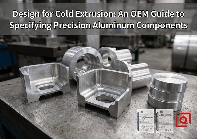
Walk onto the floor of any high-volume aluminum OEM facility. Listen to the presses. When a 500-ton hydraulic ram hits a cold aluminum slug, it doesn't just cut away material to shape a part. It forces the solid metal to flow like highly viscous putty, realigning the internal grain structure perfectly along the contours of the die cavity. We call this uninterrupted grain flow. It is the exact reason cold extruded components routinely outperform standard CNC machined equivalents in fatigue strength, impact resistance, and overall structural integrity.
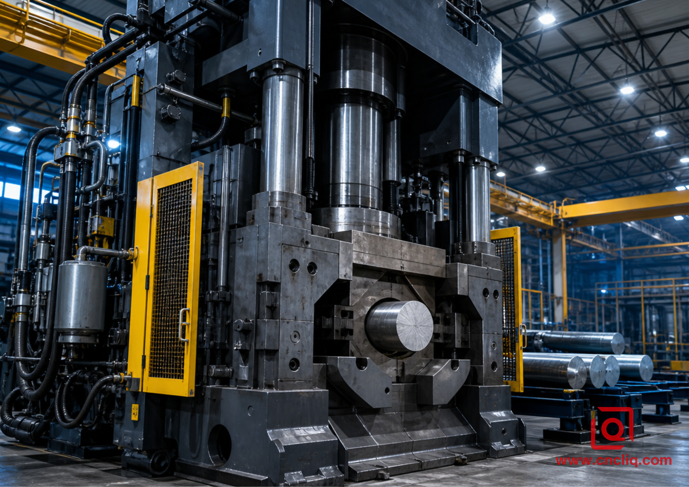
But here is the shop floor reality we deal with every single Tuesday during engineering blueprint reviews: buyers and engineers send us beautiful, highly complex CAD files that are perfectly optimized for multi-axis milling, but completely disastrous for cold extrusion. They ask for zero draft angles on 50 mm deep blind holes. They specify dead-flat internal bottoms with sharp 90-degree internal corners. That simply does not work in the extrusion world. If you attempt to run that geometry, the tool steel punch will immediately stick, the hot deformed aluminum will gall aggressively against the die walls, and your tooling life plummets from 100,000 strikes to less than 5,000. Designing for precision cold extrusion requires a fundamental shift in mechanical mindset. You are no longer managing chip evacuation. You are managing high-pressure plastic deformation.
2. Selecting the Right Aluminum Alloys
Let’s talk about alloy selection and the physical reality of flow stress. Not all aluminum grades want to flow. Pure aluminum alloys, like the 1070 series (which boasts 99.7% Al purity), yield beautifully under pressure. This material flows effortlessly into intricate, high-density heatsink fins requiring relatively low press tonnage. However, robust structural components demand the 6000 series. Alloys like 6061 and 6082 are our daily bread in the factory. They sit right in the metallurgical sweet spot—they possess enough natural ductility in the T4 temper state to survive a massive 75% cross-sectional area reduction, but they are fully capable of hitting a 290 MPa minimum tensile strength after a rigorous T6 artificial aging cycle per ASTM B221 industry standards.
What happens when a buyer demands aerospace-grade strength? You try pushing a 7075-T6 billet cold through a carbide die without annealing it first? The internal tooling shatters. The sheer flow stress of 7000 series aluminum in peak-aged conditions exceeds the compressive limits of most standard punch setups. If your project specifically dictates 7000 series aerospace grades, we must first completely anneal the raw billet down to the O-temper state, run the extrusion stroke, and then subsequently perform a full solution heat treatment and rapid quench to restore the mechanical properties. Watch your material selection closely from day one. It directly dictates the required press tonnage, the die wear rate, and ultimately, your piece price.
Geometry dictates survival on the press. Sharp internal corners create immediate, catastrophic stress risers. During the millisecond of the extrusion stroke, solid metal accelerates violently around those tooling corners. If the design radius is too tight, the material shears and tears rather than flowing smoothly. You must give us a minimum of R0.5 mm on all internal corners. R1.5 mm is vastly superior. For structural wall thickness, keep it strictly uniform. Rapid, uncontrolled transitions from a 12 mm thick solid base down to a 2 mm thin cylindrical wall instantly disrupt the material flow dynamics, causing internal voids, trapped air pockets, or ugly surface folding on the exterior skin.
Then we look at draft angles. CNC machinists generally hate draft angles; extrusion toolmakers demand them. A 0.5° to 1.5° draft on the inner diameter (ID) of a deep hollow cylinder allows the punch to retract smoothly after bottoming out. Without that specific angle, you are relying entirely on the mechanical ejection pin pushing against the base to strip the part off the punch, and you risk heavily distorting the hot, freshly formed aluminum part.
| Design Feature | CNC Machining Limit | Cold Extrusion Sweet Spot | Shop Floor Note |
| Internal Draft Angle | 0° (Preferred) | 0.5° - 1.5° | Allows punch retraction; prevents galling on H13 steel. |
| Internal Corner Radii | R0.0 mm (Sharp) | R0.5 mm - R2.0 mm | Eliminates dead metal zones and prevents shear tearing. |
| Wall Thickness Variation | Infinite | Max 2:1 Ratio | Ensures uniform flow velocity; prevents surface folding. |
| Blind Hole Depth-to-Width | > 10:1 (Peck drilling) | Max 4:1 (Forward extrusion) | Punch wandering occurs if unsupported length is too extreme. |
| Standard ID Tolerance | ±0.01 mm | ±0.05 mm - ±0.10 mm | Requires hybrid CNC finish pass if tighter specs are needed. |
How do we actually prep a production run? We don't just dump raw slugs into the hopper. Here is our exact, uncompromised shop-floor chemical preparation sequence for a tight-tolerance automotive batch:
-
Validate slug volume dynamically. The aluminum billet mass must perfectly match the mathematically calculated finished part volume, plus a tiny, highly controlled flash allowance. We strictly hold ±0.5% weight variation.
-
Alkaline clean at 65°C. We aggressively strip all residual machining cutting fluids left from the billet sawing process.
-
Submerge in a zinc phosphate bath. Bare aluminum sliding against bare tool steel under 400 tons of force is a guaranteed recipe for cold welding. The acid reaction builds a micro-porous crystalline layer on the aluminum skin.
-
Immerse in a reactive sodium stearate soap bath at 70°C. The soap reacts chemically with the zinc phosphate layer to form zinc stearate. This specific compound has a melting point higher than the intense friction heat generated during the extrusion stroke.
-
Preheat the tungsten carbide dies to 150°C. Cold tooling drastically chills the outer skin of the aluminum slug upon contact, immediately spiking the material flow stress and causing surface tearing.
-
Run the first five pieces. Pull them off the line. Section one part directly down the middle axis. Etch the cross-section with Keller's reagent. We put it under the metallurgical microscope to verify the flow lines are perfectly continuous around the critical flange radius. If the lines cut out, the metal sheared. We immediately drop the ram speed from 45 mm/s down to 28 mm/s.
3. Engineering Case Study: Slashing Scrap by 82% on a Blind-Hole Sensor Sleeve
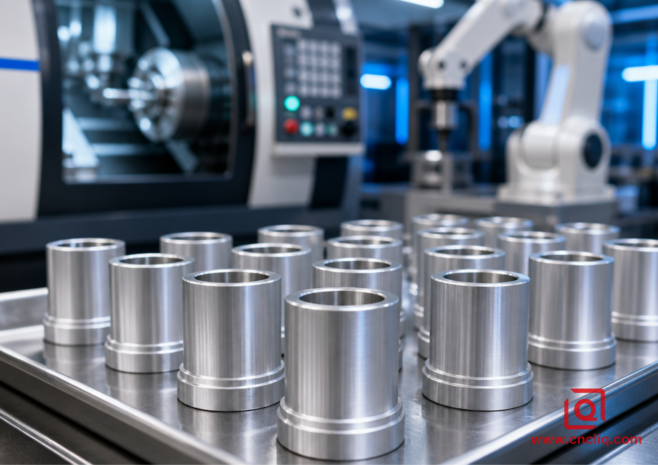
Let us look at a specific, real-world case study. An anonymous Tier-1 automotive supplier needed a continuous batch of 50,000 blind-hole sensor sleeves per month for a high-pressure fluid monitoring system. The original engineering drawing explicitly specified 6061 aluminum, an internal diameter of 18 mm, a total depth of 65 mm, and a thin uniform wall thickness of 1.5 mm. Their initial validation prototype was purely CNC turned from solid bar stock. The cost per unit was absolutely bleeding their procurement budget dry because they were turning roughly 82% of the expensive raw aluminum bar into scrap chips. They came to us seeking a high-yield cold extrusion OEM solution.
The core problem was buried in the dimensional tolerances. The original blueprint demanded a perfectly flat bottom inside the deep blind hole, sharp 90-degree internal corners, and a punishing ±0.015 mm tolerance on the entire 65 mm ID span.
We got their lead engineering team on a call and explained the exact physics of the die cavity. When a flat punch bottoms out under maximum pressure, the displaced metal has to squeeze outward and violently travel up the sides of the tool. A sharp corner entirely restricts that critical lateral flow, trapping a wedge of static aluminum—what we call a dead metal zone. The metal around it shears past this zone, creating a severe localized weak spot prone to pressure blowout.
We proposed a mandatory design modification: we added a 1.5 mm internal fillet radius at the base of the bore, and a 0.75° continuous draft on the inner wall to ensure we could strip the part off the punch at high speeds without galling. Regarding the tight ID tolerance, ±0.015 mm is simply physically impossible for an extrusion press to hit straight out of the die. Standard precision extrusion routinely delivers ISO 2768-mK or IT9 grades. We confidently promised ±0.08 mm straight off the press bed.
The manufacturing compromise was highly effective. We first cold extrude the near-net shape to instantly capture that massive 82% material savings and lock in the superior work-hardened grain structure. Then, we seamlessly chuck the extruded blanks into a custom automated CNC lathe setup. We run a rapid, highly aggressive 6-second finish pass strictly on the ID and the flat bottom to hit that exact ±0.015 mm spec. The client reviewed the hybrid process and approved it. We ran the 6061 slugs, put them through a T6 heat treatment, and delivered the first 50,000 batch exactly 38% under their original target cost. During their internal 120-bar pressure testing phase, they recorded zero structural defects.
4. Post-Extrusion Surface Integrity: Stress Relief and Anodizing Control
Finally, do not ignore post-processing realities. Cold extrusion inherently leaves massive residual stresses locked inside the aluminum matrix. You cannot just throw these freshly formed parts straight into a harsh anodizing bath and expect flawless, aerospace-grade cosmetics. The extreme compressive pressure heavily work-hardens the surface skin. If the client drawing requires a strict Type II sulfuric acid anodize per MIL-A-8625 standards, we always mandate a thermal stress-relief bake or a highly monitored caustic etch time. A standard automated 5-minute chemical etch will aggressively attack and expose the severe grain deformation near the shear zones, resulting in an ugly, striped, uneven matte finish. We specifically dial the caustic etch back to a precise 90 seconds. We clean, brighten, and anodize it. Then we seal the pores in a nickel acetate bath. The final result is a cosmetically flawless, structurally dominant OEM component that simply cannot be replicated by basic machining.
FAQs
Q1: What is the typical tooling cost for a custom aluminum cold extrusion run, and when does it break even compared to CNC machining?
Custom cold extrusion tooling usually runs between $3,500 and $12,000. That spread comes down to part geometry, insert count, and whether you spec tungsten carbide or heat-treated H13 steel. Against multi-axis CNC milling, you typically hit the cross-over at 3,000 to 5,000 pieces. Past that threshold, material savings do the heavy lifting—slashing chip loss from 70%+ to under 15%—while a 2 to 6-second press cycle eats up the front-end die spend fast.
Q2: Can we achieve tight hole and thread tolerances directly off the extrusion press without secondary operations?
No. Precision cold extrusion can comfortably hit dimensional tolerances of ±0.05 mm to ±0.10 mm (IT8–IT9 grade) straight off the die. However, features like blind internal threads, precision bearing bores (±0.01 mm), or o-ring grooves with critical surface finishes still require a rapid secondary CNC turning or milling pass. Our standard approach is near-net shape cold extrusion to build the core geometry, followed by high-speed CNC finishing for tight tolerance features.
Q3: Which aluminum alloy provides the best balance between extrusion yield and finished structural strength?
For general structural and automotive applications, 6061 and 6082 alloys offer the best operating envelope. In their softer T4 condition, they deform smoothly under high tonnage without splitting or causing premature tool wear. Once formed, a standard T6 precipitation heat treatment (solution heat treating, water quenching, and artificial aging at 175°C) elevates their tensile yield strength past 240 MPa.
Q4: How does cold extrusion improve the fatigue life of an aluminum part compared to machining it from bar stock?
When you machine a part from extruded bar stock, the cutting tool severs the continuous metallic grain flow lines at every shoulder, thread, and corner, creating micro-notches that invite fatigue cracking under cyclic load. Cold extrusion redirects and compresses the grain structure along the exact geometry of the die cavity. Because the crystalline flow lines remain unbroken and parallel to the part contour, fatigue limit and burst pressure resistance increase by 20% to 35%.
Q5: What surface finish can we expect directly from the cold extrusion dies, and does it support color anodizing?
Right off the die, cold extrusion drops you at Ra 0.4 µm to Ra 1.6 µm—noticeably cleaner than standard castings or raw machined faces. That said, severe plastic flow and heavy lube films leave a stubborn skin. You have to strip that down with hot alkaline wash and dialed-in caustic etching before the tank. Once that prep is dialed, cold-formed 6061 takes Type II and Type III hardcoat uniformly, clean of any porosity blowouts.
Summary
If you want high-volume OEM aluminum cold extrusion to pay off, your design playbook has to change: stop drawing for chips and start mapping metal flow. Give parts healthy corner rads, real-world draft, and balanced wall sections. Tackle tough tolerances with a split game plan—let the press push out near-net blanks with unbroken grain alignment, then send the piece to high-speed CNC for tight tenths. When your 3D models respect the physics of plastic flow, you trim scrap down, keep dies running longer, and pack in solid fatigue endurance at pennies on the dollar.
Contact Information
Disclaimer
All technical articles, material specifications, machining recommendations, and surface treatment details published on this blog are for informational and reference purposes only. Please note that general blog insights do not replace signed technical agreements. Because custom parts vary by material heat numbers, machine calibrations, and specific tolerances, binding quality specs are governed solely by your approved CAD drawings, signed contracts, and formal quality plans.
All customer case studies featured on this blog have been thoroughly anonymized and sanitized. The performance metrics, manufacturing workflows, and imagery displayed serve solely to demonstrate our custom machining capabilities and do not represent a single universal standard for all orders.
Liqin Manufacturing Team
Built on 18 years of precision engineering experience, Ningbo Liqin Industry manufactures high-tolerance metal components for demanding global markets. We operate out of a 6,500 m² production hub equipped with over 150 machines, running 4-axis and 5-axis CNC machining, mill-turn machining, cold extrusion, and pressure die casting under one roof. This setup allows us to manage projects seamlessly, taking parts from initial CAD concepts directly to finalized shipments.
We handle quality control with zero compromise. We treat tight tolerances with the engineering discipline they require. Backed by ISO 9001, ISO 13485, and IATF 16949 certifications, our QA engineers run strict IPQC, FQC, and OQC checks on every single production batch. From CMM dimensional mapping and optical profiling to hardness and salt-spray testing, we validate your critical specs upfront—so you receive drop-in ready components with zero assembly headaches or costly line stoppages. On top of manufacturing, you can rely on us for two-hour response times on new RFQs, direct support for prototype sampling, and smooth export shipping across Europe, North America, Asia, and Oceania.
Welcome your inquiries and samples. Visit our website or contact us directly for a competitive quote!
