 English




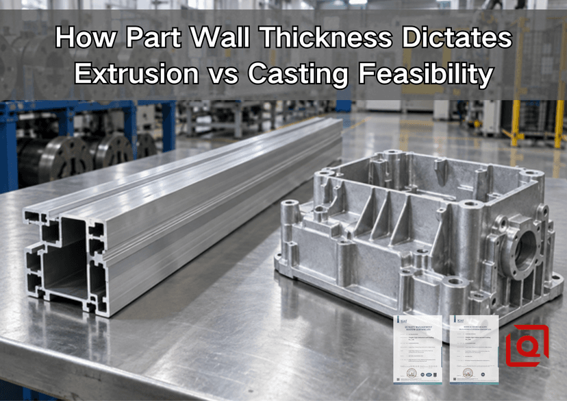
Are you still debating whether a thin aluminum housing should be extruded or cast? A supplier may say both are possible, yet the drawing tells a more complicated story. A 1.5 mm wall can be routine in one cross-section and troublesome in another. Add a long flow path, an isolated boss, a deep pocket, or a sudden 5.0 mm pad, and the process window changes again. This guide explains how a shop-floor engineer reads wall thickness before recommending aluminum extrusion, high-pressure die casting (HPDC), or a formed blank followed by CNC machining.
The practical message is simple: nominal thickness alone never chooses the process. We must read thickness together with shape, continuity, flow distance, alloy, tolerance, surface requirement, annual demand, and the features that still need machining. Liqin’s broader aluminum extrusion vs. casting selection guide compares the full process routes. Here we stay deliberately focused on the wall itself: where it runs, where it changes, how it fills, and how it will be inspected.
Need a fast feasibility answer? Send a STEP file, a dimensioned PDF, the target alloy, annual quantity, finish, and the 3 most critical dimensions. Mark pressure-tight or cosmetic zones. Our engineers can identify high-risk wall transitions before tooling is released and prepare a process-specific quotation.
1. Wall Thickness Is a Flow Map, Not Just a Drawing Callout
On an extrusion drawing, wall thickness is the gap through which hot billet metal must flow continuously as the profile passes through the die. Every web, fin, flange, and hollow chamber repeats along the extrusion direction. If one region is much thinner than its neighbors, resistance rises there. The thicker region wants to move faster. The die designer then has to balance bearing lengths and local restrictions so the profile exits at a similar speed across the whole section.
On a die-casting drawing, thickness governs a different race. Molten alloy must travel from the gate, displace air through vents or vacuum channels, reach the end of fill, and remain feedable while pressure intensifies—all before the thin front freezes against the steel tool. A thin local wall near the gate may fill cleanly. The same wall at the far end of a long, branching path may misrun. This is why “our foundry can cast 1.2 mm” is not a complete feasibility statement.
The factory question is therefore not “What is the minimum wall?” It is “Can this particular wall fill or flow consistently, remain straight after cooling, survive trimming and handling, accept the specified finish, and hold the dimensions that matter?” That fuller question prevents a risky capability number from being treated like a guarantee.
2. Quick Feasibility Matrix for Buyers and Design Engineers
|
Drawing condition |
Extrusion response |
HPDC response |
Engineering direction |
|
Constant cross-section along one axis |
Strong fit; walls, fins and hollow channels repeat through the die |
Possible, but the 3D tool may add cost without adding value |
Start with profile extrusion, then saw and machine local features |
|
Wall changes shape in several directions |
Cannot form changes along length directly |
Strong fit when cavity, slides and ejection can create the geometry |
Start with HPDC for stable higher-volume demand |
|
Long, balanced 1.0–1.5 mm webs |
Potentially feasible; envelope, tongue support and tolerance remain decisive |
Requires gate, vent, flow-length and hot-spot review |
Compare the complete fill or flow path |
|
Thin wall next to a massive boss |
Unequal flow and cooling can distort the section |
Thermal-mass contrast can create shrinkage or porosity |
Core mass, use ribs, blend the transition |
|
Pressure-tight body with machined seal |
Useful start if geometry is linear |
Porosity needs validation and controlled machining allowance |
Define leak test and critical zones first |
|
Critical bore or gasket land |
Usually finish-machine |
Usually finish-machine |
Reserve tight tolerance for CNC finishing |
Indicative wall ranges are screening references, not acceptance criteria. Liqin’s published comparison lists approximately 1.0 mm for extrusion depending on die geometry and approximately 1.2 mm local / 2.0 mm structural average for HPDC. Another Liqin guide uses 1.5–4.0 mm as an optimal HPDC range. Confirm the correct value against the complete drawing, alloy, tool, press and quality plan.
3. When Thin Walls Favor Aluminum Extrusion
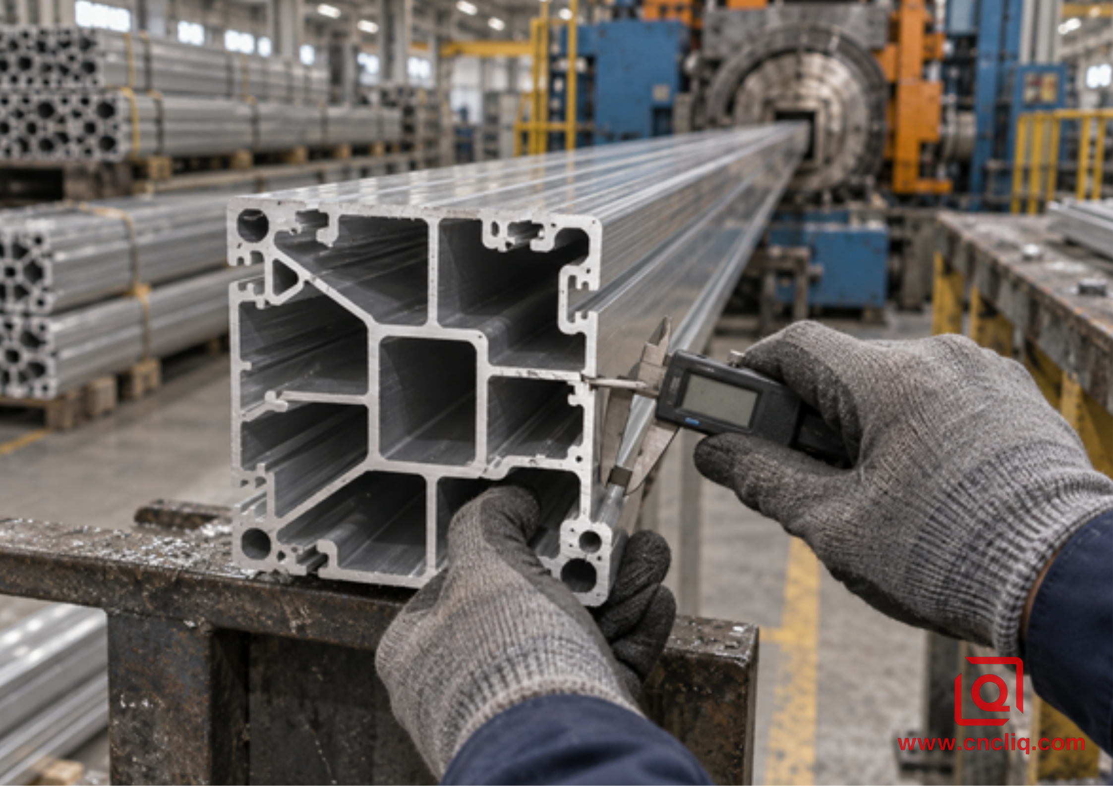
Figure 1. A wall callout is reviewed with the whole hollow profile, not in isolation.
Extrusion earns its place when the thin wall belongs to a continuous two-dimensional section. Heatsink fins, enclosure rails, round sleeves, wire channels, frame members, and long hollow profiles all use this advantage. A single die establishes the section; cutting and secondary machining create the final length, ports, threads, pockets, and end faces.
Balanced thickness makes the die easier to control
Imagine a profile with a 1.2 mm outer wall on one side and a 5.0 mm mounting rail on the other. The heavy rail offers an easier flow path. The thin wall resists flow and may lag, pulling the profile toward one side as it exits. A skilled die maker can adjust bearing lands, but the design begins with a handicap. If the rail can be hollowed, split into ribs, or reduced with gradual transitions, flow becomes easier to balance and the profile is less prone to twist.
Symmetry also helps. It is not mandatory, but roughly balanced mass around the profile center lowers the correction required at the die and during stretching. Very deep, unsupported die tongues are another warning. A narrow slot around a long tongue can deflect the steel feature, creating wall variation or premature die wear. Treat a thin wall surrounded by a stable die ring differently from a thin wall formed around a fragile projecting tongue.
This matches the Aluminum Extruders Council’s design guidance, which recommends balanced walls, symmetry where practical, generous tapers, useful ribs and webs, and avoidance of high tongue ratios. Its value is not a universal minimum-wall number; it is a reminder that the complete cross-section determines extrudability and cost.
Thin does not automatically mean light or cheap
Reducing a wall from 1.5 mm to 1.0 mm removes material, but it may also slow the press, increase die correction trials, tighten straightening control, and make handling dents more likely. The apparent material saving can be smaller than the added conversion cost. A useful RFQ therefore asks for target part mass and performance, not simply “the thinnest possible profile.”
The alloy matters too. Liqin’s site commonly associates 6063 with precision profile extrusion because it flows and anodizes well, while 6061 and 6082 may be chosen when mechanical requirements justify a less forgiving extrusion window. Alloy and temper must be agreed before the die is finalized; a later substitution can change press behavior, mechanical properties, finish, and tolerance.
What extrusion cannot carry along the length
A cross-hole, stopped pocket, local platform, perpendicular boss, or connector opening does not repeat along the press axis. It must be added afterward. That is not a process defect; it is the normal hybrid route. Extrude the material-efficient section, cut it, then CNC-machine only the functional details. For critical bores and mating surfaces, this separates economical near-net forming from precision finishing. See Liqin’s CNC machining, die casting and extrusion guide for the broader tolerance and volume trade-off.
For procurement specifications, ASTM B221/B221M covers aluminum and aluminum-alloy extruded bars, rods, wire, profiles, and tubes, including composition and mechanical-property requirements. It does not turn a difficult profile into an easy one, and pressure applications may need other product standards and verification, but it gives buyers a traceable basis for material and temper requirements.
4. When Wall Geometry Pushes the Part Toward Die Casting
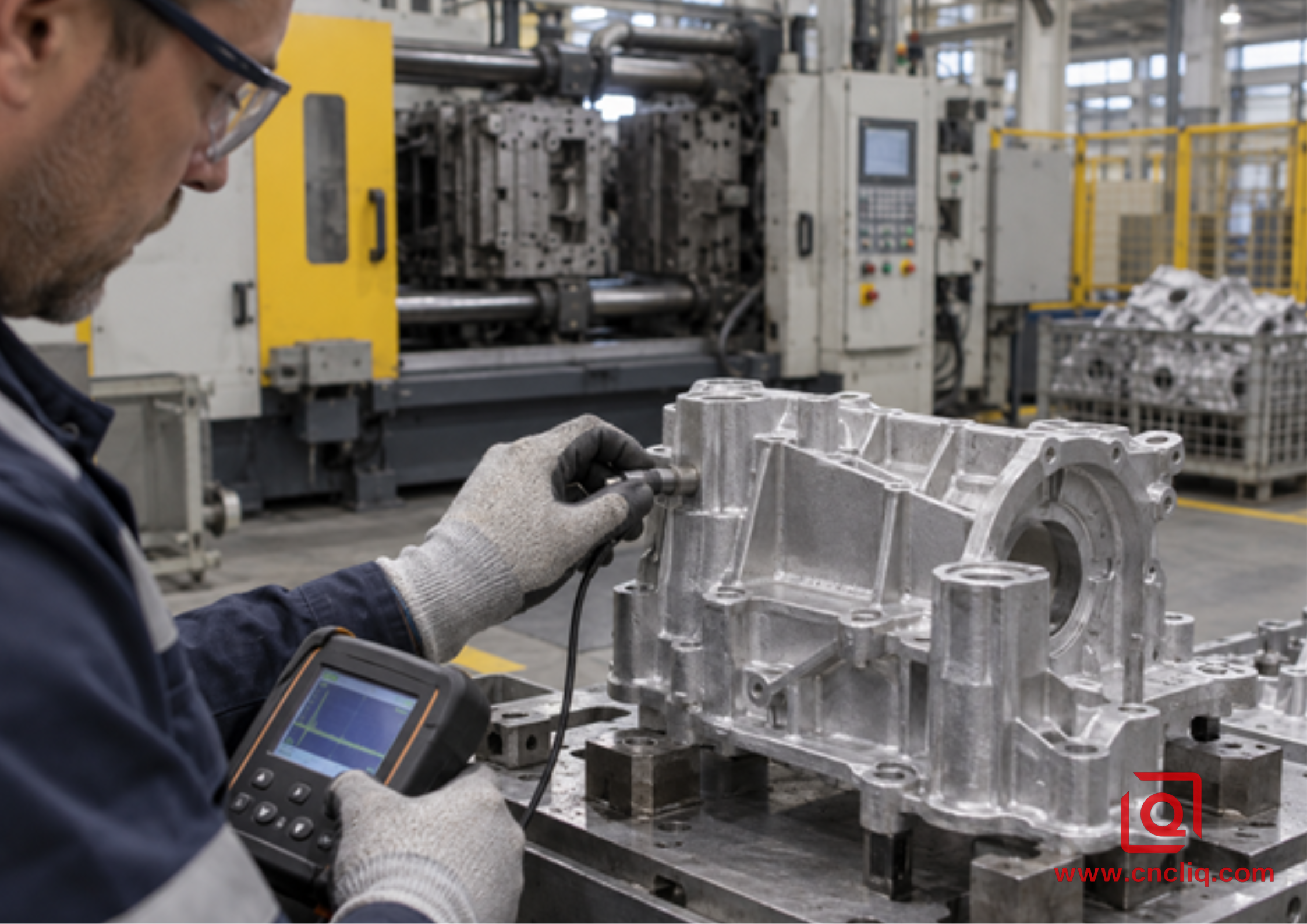
Figure 2. HPDC feasibility depends on wall thickness, gate distance, venting and local thermal mass.
HPDC becomes attractive when the part changes section along several axes and can justify dedicated tooling. One shot may form an enclosure cavity, curved outer wall, internal ribs, bosses, cable routes, mounting feet, and identification recesses. Extrusion would require extensive removal or assembly to create the same three-dimensional body.
Flow length makes the same wall behave differently
A thin section freezes quickly because the steel die extracts heat rapidly. As the distance from the gate increases, the melt front loses temperature and pressure. Narrow turns, split streams, and abrupt cross-sectional changes consume more of the available fill window. Foundry engineers therefore review wall thickness with gate location, runner area, vent position, overflow placement, alloy fluidity, die temperature, shot profile, and vacuum strategy. A minimum-thickness claim without those variables is only marketing shorthand.
Uniform walls reduce thermal surprises
HPDC prefers relatively uniform structural walls. A 1.8 mm shell that suddenly feeds into a solid 8.0 mm boss creates a hot island. The shell solidifies first while the boss remains liquid longer and contracts later. The junction may develop shrinkage or internal porosity, especially if feeding and intensification are poor. The usual DFM response is to core the boss, tie it into the wall with ribs, and add a smooth fillet instead of simply thickening the area.
The North American Die Casting Association similarly identifies uniform wall thickness, sufficient draft, and fillets or radii as core design practices. Those are not decorative preferences: they support filling, cooling, ejection and repeatability. Liqin’s custom aluminum die-casting OEM playbook carries the same principles into tooling and production checks.
Ribs add stiffness without turning the whole wall into a heavy heat sink. They still need sensible roots and spacing. A thick rib planted sharply on a thin skin recreates the same mass problem at a smaller scale. Draft must also be included so the part can release from the tool without scuffing or distortion.
Secondary machining changes the wall budget
Designers sometimes specify a thin cast wall and then place a deep machined pocket or sealing face on it. The machining allowance is part of the final wall equation. Removing too much material may uncover subsurface porosity or weaken a wall that was acceptable in the as-cast state. The 2D drawing should state the required finished thickness and identify whether dimensions apply before or after machining and coating.
ISO 8062-3:2023 supplies a recognized framework for general dimensional and geometrical tolerances and machining-allowance grades for castings using indicated plus/minus tolerances. It is useful contract language when correctly referenced on the drawing, but critical sealing, bearing, position and wall features should still be called out individually.
Use CNC only where function demands it: gasket lands, bearing bores, datum pads, threaded ports, and controlled interfaces. Liqin’s published precision aluminum light housing illustrates this hybrid logic: the housing form, cooling fins and bosses are die-cast, while sealing faces, gasket tracks and threaded holes receive precision machining.
5. Wall Transitions: The Most Expensive Millimeters on the Drawing
Most feasibility disputes are not caused by a large region of uniform wall. They start at the transition. Look closely at where a thin shell meets a flange, where a rib joins a boss, where a hollow extrusion closes around a port, or where a machined counterbore approaches an as-formed surface.
|
Risk feature |
Extrusion failure mode |
HPDC failure mode |
DFM response |
|
Abrupt thin-to-thick step |
Unequal velocity, twist, dimensional imbalance |
Hot spot, shrinkage, porosity or distortion |
Taper change; hollow heavy sections; use supported ribs |
|
Sharp internal corner |
Difficult flow and concentrated die stress |
Poor fill and stress concentration |
Add practical radii and blend junctions |
|
Long unsupported fin |
Die-tongue deflection, waviness, handling damage |
Incomplete fill or bending during ejection |
Shorten, brace, thicken locally, or change spacing |
|
Deep machining beside thin wall |
Clamping distortion and chatter |
Breakthrough or exposed porosity |
Define the finished minimum wall |
|
Tight tolerance over a long span |
Bow and twist dominate |
Thermal drift, shrinkage and warpage dominate |
Move precision to local datums |
A useful design review colors the model by wall bands rather than checking one nominal value. Mark thin, nominal, heavy, machined, sealing, cosmetic, and pressure-retaining zones. The resulting map makes the toolmaker’s questions visible to the buyer and helps avoid a vague quotation padded with risk.
6. Practical Decision Sequence Before You Request a Quote
1. Rotate the model along every axis. If one cross-section repeats continuously, extrusion deserves the first review. If geometry changes on several faces, HPDC may remove more secondary work.
2. Measure minimum, nominal and maximum wall. Identify the length and location of the thinnest region and the largest adjoining mass.
3. Mark functional zones. Separate structural, pressure-tight, heat-transfer, cosmetic, sealing and machining surfaces.
4. Define alloy and finish. Wrought and casting alloys behave differently in flow, strength and anodizing. Do not expect identical cosmetic results from 6063 extrusion and silicon-rich A380 or ADC12 casting.
5. Add tolerance after choosing the process. A profile can be straightened and locally machined; a casting can be trimmed and finish-machined. Avoid forcing the whole near-net part to match one critical bore.
6. State demand honestly. Dedicated HPDC tooling needs stable repeat volume. Extrusion tooling is generally simpler, but short cut lengths and extensive machining still affect economics.
7. Request evidence tied to risk. Ask for a wall-thickness plan, CMM or profile inspection, sectioning or X-ray where justified, leak-test criteria for pressure parts, and first-article approval before mass production.
7. Anonymous Case Study: Reframing a Finned Lighting Housing
This anonymized engineering scenario is derived from the feature set published on Liqin’s aluminum light-housing product page; it explains DFM reasoning and does not disclose a customer or promise universal results.
An overseas industrial-lighting buyer submitted a housing with a broad internal cavity, external cooling fins, perimeter sealing surface, threaded cable entries, mounting bosses, and a dense blind-hole pattern. The first sourcing discussion treated the part as a choice between “thin-wall extrusion” and “die casting.” That framing was incomplete.
Viewed from the end, the fin field looked compatible with extrusion. Viewed from the top and underside, however, the body changed repeatedly: local bosses rose from the floor, cable entries crossed the main axis, the cavity footprint varied, and the sealing flange wrapped around a three-dimensional enclosure. Producing the full body from a long profile would require removing large areas, attaching or machining several local features, and managing a long sealing perimeter after multiple operations.
The DFM direction was therefore a hybrid HPDC blank with CNC finishing. The casting tool would form the cavity, fins and principal bosses. The wall map would keep the main shell reasonably uniform, core heavy bosses, and blend their roots with ribs and fillets. CNC operations would then control the sealing face, gasket track, threaded ports and blind-hole depths. The inspection plan would separate as-cast wall checks from finished critical dimensions so a good casting could not be weakened accidentally during machining.
No invented cost saving, scrap rate or lead-time claim is attached to this scenario. Measurable acceptance items would come from the approved drawing and quality plan: wall locations, finished dimensions, flatness, thread verification, coating requirements and any agreed leak or ingress test. That transparency is more useful than a dramatic percentage without traceable production records.
The lesson is not that casting always wins for a finned enclosure. If the body were a constant-length heatsink rail with identical ends, extrusion could be cleaner. Here, the local three-dimensional features—not the isolated minimum wall number—decided the process. Buyers comparing a cylindrical deep-cavity part should also distinguish profile extrusion from aluminum cold extrusion versus die casting, because the tooling motion and feasible geometry are different.
8. Inspection: Prove the Wall You Quoted
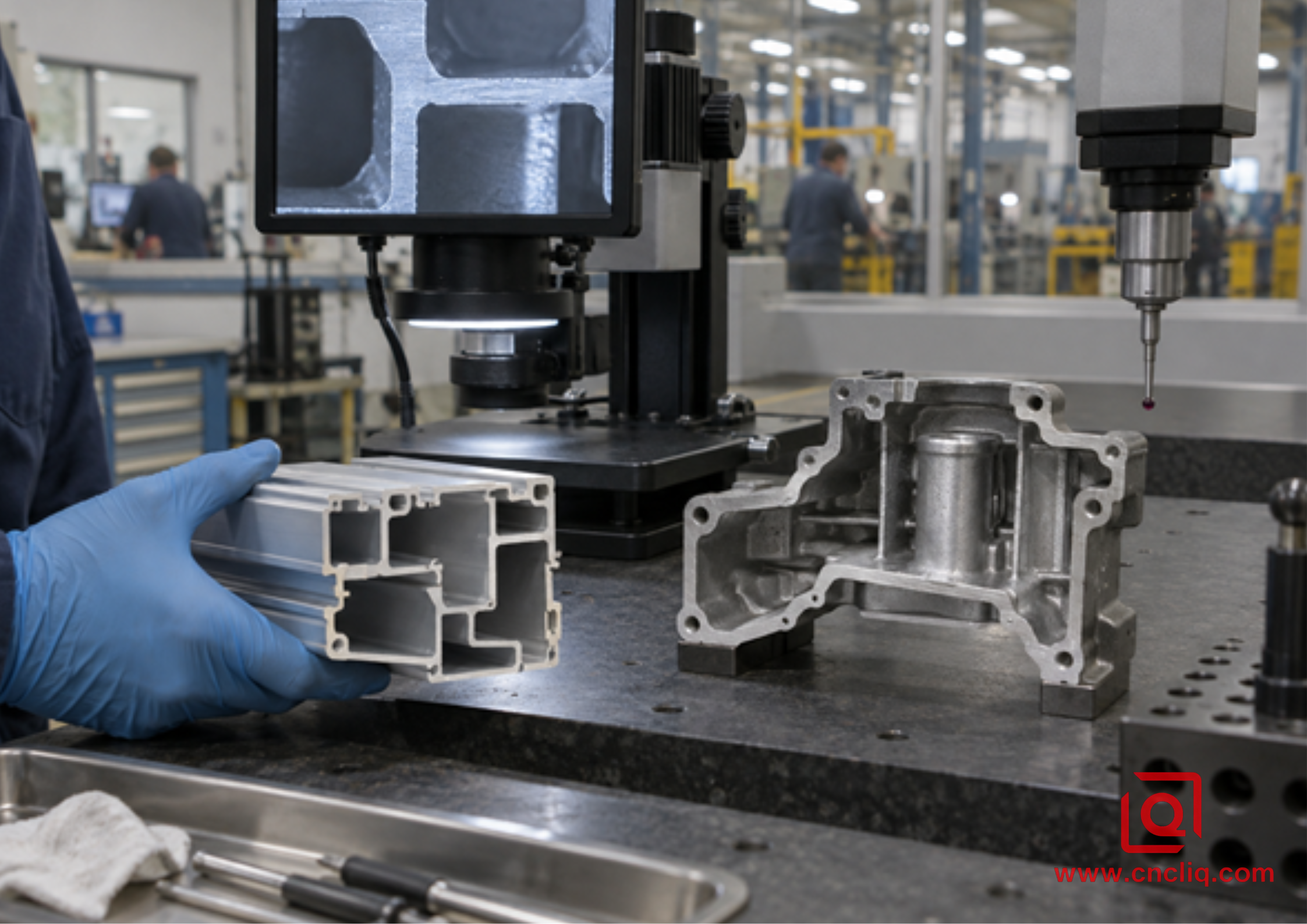
Figure 3. Section measurements and dimensional inspection turn a wall-thickness promise into objective evidence.
For an extrusion first article, measure the complete section rather than a single easy-to-reach wall. Optical profiling or section measurement can capture webs, internal chambers, corner radii and local thickness. Straightness, twist and cut-length squareness should be checked separately because an acceptable section can still create assembly problems over a long span.
For a casting first article, wall measurement should follow the fill path and the identified hot spots. Mechanical sectioning gives direct evidence on development samples. Non-destructive methods may be appropriate where the quality plan requires them, but the method and acceptance rule must be agreed. Dimensional inspection, leak testing and internal-integrity checks answer different questions; passing one does not automatically prove the others.
After secondary machining, verify the remaining wall at critical pockets, ports and sealing areas. A CMM confirms accessible geometry, while dedicated gauges or other validated methods may be needed for hidden sections. Link each measurement to a drawing balloon and acceptance criterion. “Looks good” is not a production control plan.
9. What to Send for a Reliable Extrusion or Casting Quote
A quotation is only as reliable as the engineering package behind it. Send the 3D model in STEP or IGES format and a controlled 2D PDF with datums, tolerances, material, finish, revision, and inspection notes. Add annual volume, order lot size, target life, assembly loads, operating temperature, cosmetic zones, leak-test pressure if applicable, and any regulatory documentation required by your market.
For wall-thickness review, include 3 extra items: the minimum finished wall after machining, permission or restrictions on coring heavy sections, and a ranked list of dimensions that cannot move. That information lets the factory propose a real DFM trade rather than silently thickening the whole part or quoting an unnecessarily expensive process.
Turn the drawing into a production plan. Send Liqin your CAD file, target volume and critical-wall map through the contact page. Ask for an extrusion/HPDC feasibility comparison, the proposed secondary-machining route, and an inspection plan with the quotation. This gives procurement a clearer basis for comparing tooling cost, unit cost and manufacturing risk.
FAQs
1. Is 1.0 mm wall thickness automatically better suited to extrusion than die casting?
No. A 1.0 mm wall in a compact, balanced, constant cross-section may suit an extrudable alloy, while the same number around a deep unsupported tongue may be difficult. In HPDC, a short thin wall near a well-designed gate behaves differently from a long remote wall after several turns. Use 1.0 mm only as a screening input; final feasibility depends on geometry, alloy, die design, press, tolerance and inspection.
2. Why do suppliers ask us to make casting walls more uniform?
Uniform walls fill and cool more predictably. A thick boss attached abruptly to a thin shell stays hot after the shell begins to solidify, which can concentrate shrinkage or porosity at the junction. Coring the boss, adding proportionate ribs and blending the root reduce the thermal-mass jump without sacrificing local stiffness. The design still needs tool-specific validation where risk is high.
3. Can extrusion produce bosses, holes and gasket grooves?
It can produce features that repeat continuously along the extrusion axis, such as screw channels, fins and hollow passages. A local boss, cross-hole, stopped pocket or gasket groove usually requires secondary machining, punching or another operation. The economical route is often to extrude the efficient base section and machine only the local features whose position, finish or tolerance matters.
4. Which process is safer for a pressure-tight aluminum housing?
There is no universal winner. A wrought extrusion can provide a useful continuous structure when the body is linear, but end closures and machining still need validation. HPDC can form a complex enclosure efficiently, yet internal porosity, gate strategy and machining depth must be controlled. Give the supplier the pressure medium, test pressure, allowable leakage, duty cycle and critical sealing zones.
5. What is the fastest way to get a credible process recommendation?
Send a STEP model, dimensioned PDF, alloy, finish, annual quantity and critical-feature list. Mark minimum finished walls, cosmetic faces, pressure zones, sealing lands and surfaces that will be machined. A supplier can then review constant cross-sections, thin-to-thick transitions, die access, fill distance, draft, secondary operations and inspection. A screenshot with one wall dimension is not enough.
Summary
Wall thickness dictates extrusion versus casting feasibility only when it is read as part of the entire manufacturing system. Extrusion is strongest when balanced walls repeat through a constant cross-section; HPDC is strongest when stable three-dimensional geometry, ribs and bosses can be formed in one tool. In both processes, abrupt mass changes, unsupported thin features and careless machining allowances create more risk than a nominal number alone. Map the wall, define function and volume, reserve tight tolerances for critical interfaces, and obtain process-specific DFM evidence before releasing tooling.
Contact Information
Company: Ningbo Liqin Industry Co., Ltd.
Daily customer maintenance & after-sales support:service@shturl. zhuwanying@cncliq.com
New inquiry, quotation & order discussion:business@shturl. zhouli@chinaliqin.com
Hotline: +86 18757148656
Disclaimer
All technical articles, material specifications, machining recommendations, and surface treatment details published on this blog are for informational and reference purposes only. Please note that general blog insights do not replace signed technical agreements. Because custom parts vary by material heat numbers, machine calibrations, and specific tolerances, binding quality specs are governed solely by your approved CAD drawings, signed contracts, and formal quality plans.
All customer case studies featured on this blog have been thoroughly anonymized and sanitized. The performance metrics, manufacturing workflows, and imagery displayed serve solely to demonstrate our custom machining capabilities and do not represent a single universal standard for all orders.
Liqin Manufacturing Team
Built on 18 years of precision engineering experience, Ningbo Liqin Industry manufactures high-tolerance metal components for demanding global markets. We operate out of a 6,500 m² production hub equipped with over 150 machines, running 4-axis and 5-axis CNC machining, mill-turn machining, cold extrusion, and pressure die casting under one roof. This setup allows us to manage projects seamlessly, taking parts from initial CAD concepts directly to finalized shipments.
We handle quality control with zero compromise. We treat tight tolerances with the engineering discipline they require. Backed by ISO 9001, ISO 13485, and IATF 16949 certifications, our QA engineers run strict IPQC, FQC, and OQC checks on every single production batch. From CMM dimensional mapping and optical profiling to hardness and salt-spray testing, we validate your critical specs upfront—so you receive drop-in ready components with zero assembly headaches or costly line stoppages. On top of manufacturing, you can rely on us for two-hour response times on new RFQs, direct support for prototype sampling, and smooth export shipping across Europe, North America, Asia, and Oceania.
Welcome your inquiries and samples. Visit our website or contact us directly for a competitive quote!
