 English




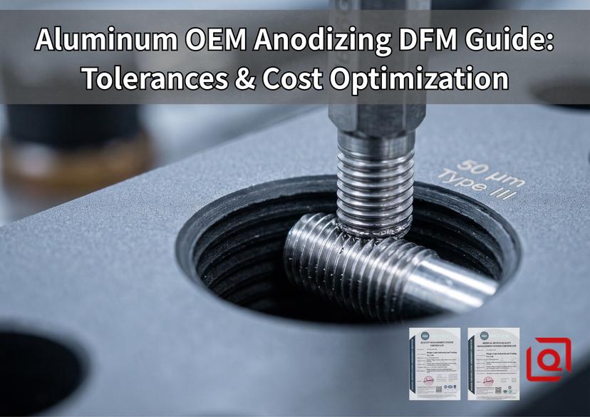
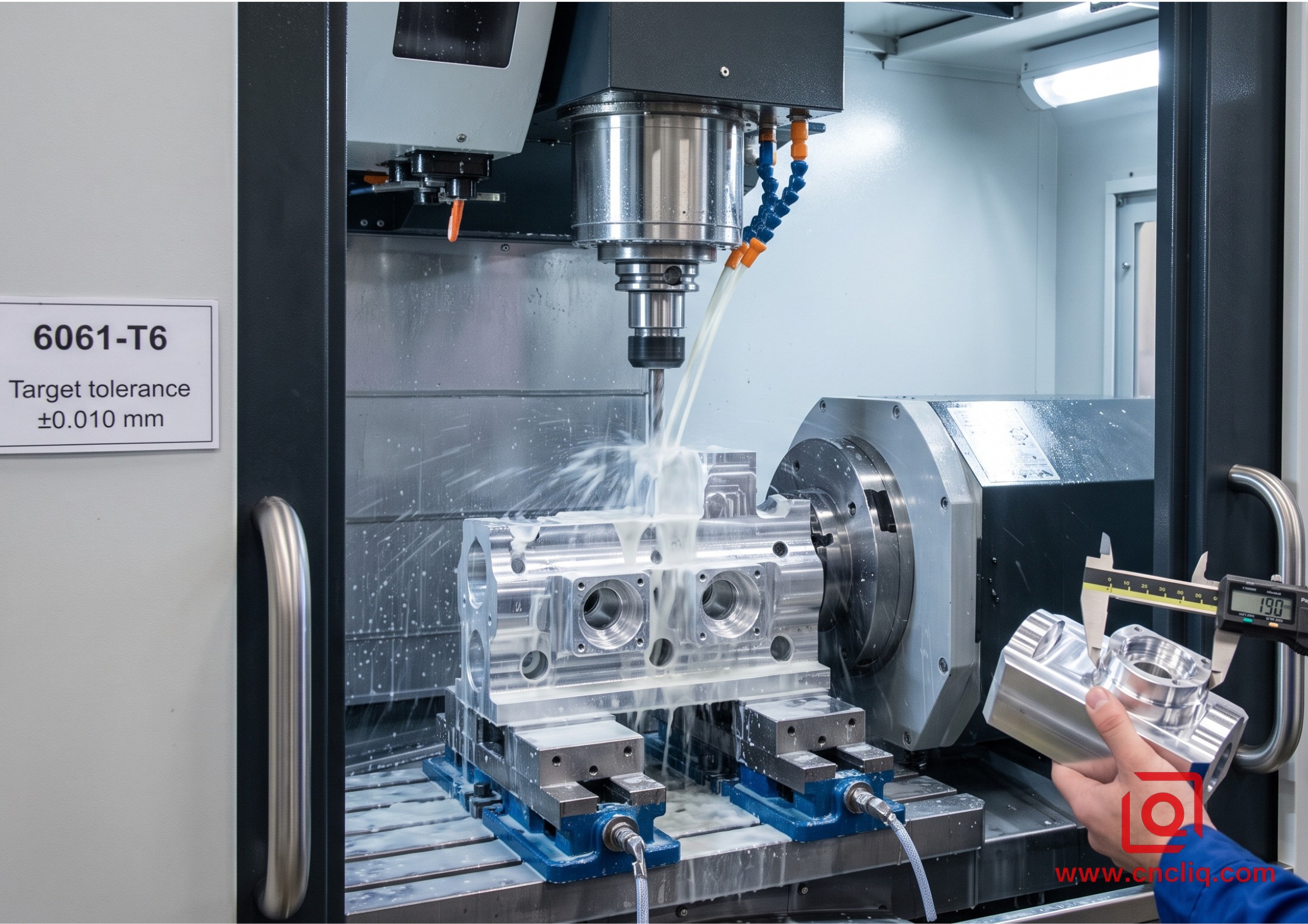
Every month, we see CAD packages land on our shop floor where the engineering drawings look flawless on a 4K monitor, but turn into an absolute headache once parts reach final assembly. We pull high-precision 6061-T6 valve blocks or 7075-T6 structural brackets off our 5-axis CNCs, hold tight ±0.010 mm machining tolerances, send them to the anodizing shop, and then watch assembly stall. M6 internal threads lock up solid, H7 pin bores shrink out of spec, and crisp outer edges start shedding micro-flakes.
Where did things go sideways? In almost every case, someone on the design team treated Type III Hardcoat Anodizing as an isolated aesthetic spray coating rather than an active dimensional variable in their overall DFM calculations.
Hard anodizing doesn't sit on top of your raw aluminum block like paint. It consumes base metal and expands outward simultaneously. If there's one rule I tell every visiting OEM designer to write on their whiteboard, it's this: 50% of the oxide layer penetrates down into the aluminum substrate, and 50% builds up on the external physical surface. Under MIL-A-8625 Type III Class 1, if you specify a 50 µm (2.0 mil) hardcoat, you are adding 25 µm (1.0 mil) of physical build-up per side. Ignore this 25 µm growth in your pre-plate CAD model, and your precision fits will fail every single time. Reamed holes choke down, bearing seats seize, and internal fasteners bind halfway down the thread bore before reaching target torque.
Process Physics & Dimensional Growth Rules
Hard anodizing drives the oxidation of aluminum into a dense, microcrystalline Al2O3 ceramic layer. Inside our tanks, we hold chilled sulfuric acid strictly at 0 to 4°C while running 2.4 to 3.6 A/dm² of current density across the bath. That setup gives us full control over turning raw aluminum into a wear-resistant skin. But here's where bath physics clashes with part geometry: current loves the path of least resistance, and it gathers heavily at sharp external corners.
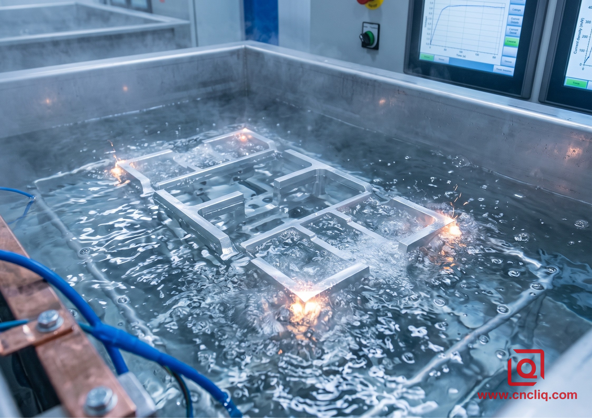
When current spikes on sharp edges, it overheats the localized solution zone, burning the tip and leaving behind a brittle, micro-cracked oxide film. On the flip side, deep blind internal holes starve the electrolyte reaction because acid can't circulate freely.
To stop outer corners from crumbling under heavy mechanical loads, you have to break every sharp edge before parts ever touch the anodizing tank. Here are the minimum fillet radius targets we require on pre-machined prints based on final coat thickness:
-
25 µm (1.0 mil) Coating: Minimum outer edge radius of 0.8 mm.
-
50 µm (2.0 mil) Coating: Minimum outer edge radius of 1.5 mm.
-
75 µm (3.0 mil) Coating: Minimum outer edge radius of 2.4 mm.
If you run a 50 µm hardcoat on a 7075-T6 bracket with an unbroken 0.1 mm edge, current crowding at that sharp apex will overheat the alloy tip. That leaves a weak, micro-fractured oxide structure. When we place those compromised parts into an ASTM B117 salt spray cabinet, the corners suffer corrosion failure at just 168 hours—falling far short of the 3,300-hour benchmark expected from industrial-grade hardcoat protection.
| Material Alloy & Temper | Anodize Type (MIL-A-8625) | Nominal Coating Thickness | Pitch / Bore Diameter Change | Max Hardness (Vickers HV) | Recommended Pre-Anodize Tolerance |
| Alloy 6061-T6 | Type III Class 1 (Clear) | 50 µm (0.050 mm) | +50 µm (+0.050 mm total OD) | 400 to 450 HV | ±0.025 mm |
| Alloy 7075-T6 | Type III Class 2 (Black) | 50 µm (0.050 mm) | +50 µm (+0.050 mm total OD) | 450 to 500 HV | ±0.025 mm |
| Alloy 5052-H32 | Type II Class 1 | 20 µm (0.020 mm) | +20 µm (+0.020 mm total OD) | 200 to 250 HV | ±0.010 mm |
| Alloy 2024-T3 | Type III Class 1 | 35 µm (0.035 mm) | +35 µm (+0.035 mm total OD) | 300 to 350 HV | ±0.018 mm |
| Cast A380.0 | Type III Class 1 | 40 µm (0.040 mm) | +40 µm (+0.040 mm total OD) | 250 to 300 HV | ±0.030 mm |
Workshop Realities: Masking Strategies & Bore Control
Threaded blind holes and tight hydraulic spool bores need a clear game plan long before parts land in the acid bath.
Shop Floor Case Study: Last year, an industrial automation customer shipped us CAD prints for a run of 500 custom hydraulic valve manifolds. Their machine shop had tapped all internal M8x1.25 threads to standard 6H limits, and then called for a 50 µm Type III hardcoat. Once anodized, every single valve spool bound up dead on the test bench. Why? Because the 25 µm layer growth per side ate up the entire pitch clearance, reducing internal thread clearance to zero.
To avoid post-plating thread binding without resorting to expensive hand-chasing operations with taps—which strips away protective oxide and exposes raw metal—we use three practical rules in our shop:
-
Cut Over-Sized Threads Pre-Anodize: Tap internal threads with 6G or custom oversize taps (+25 µm to +40 µm pitch offset). When the 25 µm coating builds up in the tank, the thread shrinks back into standard 6H compliance.
-
Custom Silicone Plug Masking: On reamed pin bores (like a 12.000 mm H7 fit), mandate custom-molded tapered silicone plugs. Sizing the plug 0.5 mm wider than the bore diameter holds off acid bypass even under 3.0 bar agitation pressure.
-
Chemical Stripping Fixes: If coating unintentionally leaks onto a critical bearing face, never try to grind it off mechanically. Grinding drives abrasive aluminum oxide particles straight into the soft aluminum base. Instead, strip the oxide layer in a warm bath of 35 g/L chromic acid and 20 mL/L phosphoric acid at 80°C for 12 minutes, then re-machine and re-process.
On the shop floor, bath temperature control determines final coat hardness. Holding our sulfuric acid bath strictly at 2°C yields a dense oxide structure that keeps Taber wear loss below 1.5 mg per 1000 cycles on CS-17 wheels (1000 g load per ASTM D4060). If a shop runs undersized chillers and lets tank temperatures drift up to 8°C, micropores in the coating expand from 12 nm to 28 nm. Coating hardness collapses from 460 HV down to 280 HV, failing scratch checks in fewer than 200 cycles.
Cost Driver Breakdown & Blueprint Callout Rules
Cost spikes in aluminum finishing stem from manual labor spent on tricky masking, poorly configured racking, and small, unoptimized batch runs. When drafting your engineering prints, ditch vague notes like "Hard Anodize High Quality." Call out explicit, actionable engineering limits:
-
Define Realistic Thickness Bands: Call out "MIL-A-8625, Type III, Class 1, 50 µm ± 5 µm" rather than a flat "50 µm minimum." Demanding an overly tight tolerance like ±3 µm forces finishing technicians to slow current ramp rates and constantly pause for eddy-current gauge checks, inflating processing unit cost by 45%.
-
Mark Racking Contact Points: Point out allowed rack contact locations on non-critical outer surfaces. A spring-loaded titanium contact clamp pulls 15 A of current per component. If a worker clips that contact onto an O-ring sealing groove, localized arcing will pit the seating surface, creating an instant leak path under 20 MPa pressure testing.
-
Never Mix Castings with Wrought Alloys: Don't try to run 6061-T6 mounting plates and A380 die-cast housings on the same anodizing flight bar. High-silicon casting alloys demand altered voltage profiles (up to 60 V) to penetrate silicon particles. Running them under wrought alloy parameters burns the 6061 components while leaving the cast housings under-coated and spotty.
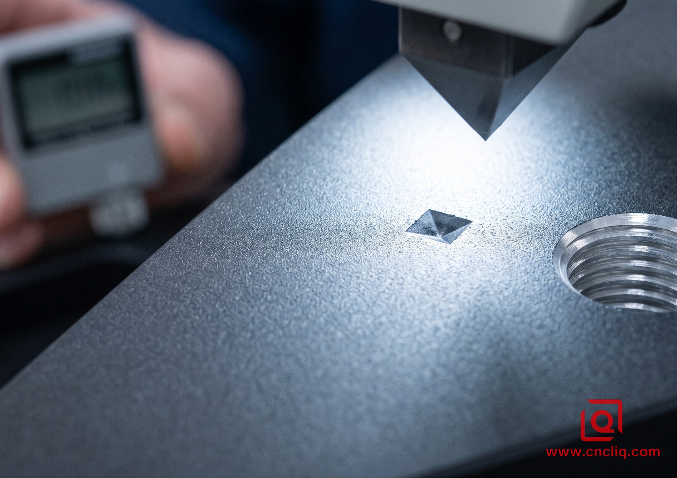
We inspect every production batch with eddy-current instruments per ISO 2360 to verify non-destructive thickness across all key features. For high-wear applications in automation hydraulics and defense components, we run microhardness testing on sacrificed tab samples per ASTM E384. Proper DFM alignment on anodizing tolerances ensures your aluminum OEM components transition smoothly from precision machining to harsh field deployment without performance compromise.
FAQs
Q1: How does rack tooling selection (Titanium vs. Aluminum) impact unit production costs and electrical efficiency in high-volume Type III anodizing?
Sure, aluminum racks save you a few bucks on day one, but they eat away in the stripping tank, shedding 12% to 18% of their cross-section every single pass. That limits them strictly to quick prototype lots under 50 units. For serious OEM production volumes, I always tell folks to spring for custom, spring-loaded titanium racking. While titanium requires a 2 V to 3 V higher initial power supply potential due to electrical resistivity, it withstands thousands of cycles without dimensional loss. Ensure clamping pressure exceeds 8 N/mm² at every contact point to prevent micro-arcing under high current densities above 3.0 A/dm².
Q2: What is the critical depth-to-diameter limit for unmasked internal blind holes before electrolyte stagnation starves oxide formation?
When internal blind hole depth exceeds a 3:1 ratio relative to its diameter, natural thermal convection fails to flush spent acid out of the cavity. Without forced solution flow at 1.2 m/s across the hole opening, localized electrolyte temperatures spike beyond 10°C, causing catastrophic oxide dissolution and thread erosion. For features exceeding a 5:1 aspect ratio, specify internal cathode spuds or mandatory ultrasonic agitation at 40 kHz during processing.
Q3: Why does high-zinc 7075-T6 require distinct current density ramping profiles compared to standard 6061-T6 alloy?
With 5.1% to 6.1% zinc, 7075-T6 spikes local conductivity and turns up the heat right at the reaction layer. Hit the bath with a full 3.2 A/dm² load right away, and you'll trigger thermal runaway—completely wrecking the oxide coating. In our shop, we program rectifiers to step-ramp current starting at 0.5 A/dm², adding 0.1 A/dm² every minute until target load. We also lock solution temps below 3°C across the entire 60-minute run.
Q4: Should Type III hardcoat anodizing be sealed, and how does sealing choice impact surface wear resistance?
Standard deionized water sealing at 96°C–100°C for 45 minutes converts Al2O3 into boehmite, plugging micro-pores against rust but knocking surface hardness down 15% to 20%—a drop from 450 HV to 360 HV. When machining high-wear sliding surfaces, I prefer skipping sealers entirely or running a brief 12-minute nickel acetate dip at 85°C. That holds microhardness over 420 HV while easily meeting the 1000-hour ASTM B117 salt spray standard.
Q5: How significantly does pre-treatment etching and hardcoat growth alter the baseline surface roughness (Ra) of precision machined faces?
Dip a clean, milled part into a 50 g/L NaOH etch at 55°C for 90 seconds, and watch the finish jump from Ra 0.4 µm to Ra 1.2 µm. Type III oxide growth then tacks on another 30% to 50% of the overall coat thickness directly onto that surface profile. If your drawing calls for a tight Ra 0.2 µm seal face, standard tank runs won't cut it. You'll want to specify pre-plate electropolishing or set up a post-anodize precision lap using 3 µm diamond slurry.
Summary
Executing precision aluminum OEM production under strict Type III Hardcoat Anodizing requirements demands treating the electrolytic finish as an active dimensional variable rather than a cosmetic afterthought. When you factor in that 50/50 penetration-versus-build-up split back in CAD, open up thread pitch clearances, break sharp corners, and hold bath temps at 0°C to 4°C, you won't have to deal with seized threads, chipped edges, or bloated scrap bins. Clear print callouts—with realistic thickness bands and marked rack points—keep your machining tolerances and surface specs on the same page. That's how we hit verified ASTM salt spray and Vickers hardness targets without driving up piece prices.
Contact Information
Disclaimer
All technical articles, material specifications, machining recommendations, and surface treatment details published on this blog are for informational and reference purposes only. Please note that general blog insights do not replace signed technical agreements. Because custom parts vary by material heat numbers, machine calibrations, and specific tolerances, binding quality specs are governed solely by your approved CAD drawings, signed contracts, and formal quality plans.
All customer case studies featured on this blog have been thoroughly anonymized and sanitized. The performance metrics, manufacturing workflows, and imagery displayed serve solely to demonstrate our custom machining capabilities and do not represent a single universal standard for all orders.
Liqin Manufacturing Team
Built on 18 years of precision engineering experience, Ningbo Liqin Industry manufactures high-tolerance metal components for demanding global markets. We operate out of a 6,500 m² production hub equipped with over 150 machines, running 4-axis and 5-axis CNC machining, mill-turn machining, cold extrusion, and pressure die casting under one roof. This setup allows us to manage projects seamlessly, taking parts from initial CAD concepts directly to finalized shipments.
We handle quality control with zero compromise. We treat tight tolerances with the engineering discipline they require. Backed by ISO 9001, ISO 13485, and IATF 16949 certifications, our QA engineers run strict IPQC, FQC, and OQC checks on every single production batch. From CMM dimensional mapping and optical profiling to hardness and salt-spray testing, we validate your critical specs upfront—so you receive drop-in ready components with zero assembly headaches or costly line stoppages. On top of manufacturing, you can rely on us for two-hour response times on new RFQs, direct support for prototype sampling, and smooth export shipping across Europe, North America, Asia, and Oceania.
Welcome your inquiries and samples. Visit our website or contact us directly for a competitive quote!
